
Related Manuals for Siemens SINAMICS SL150


Summary of Contents for Siemens SINAMICS SL150
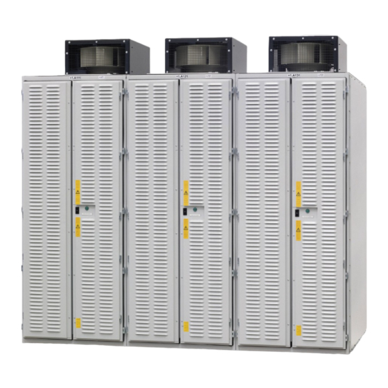
- Page 1 This documentation pertains to EXAMPLE Operating Instructions Installation Instructions Medium-Voltage Drive SINAMICS SL150 Type 6SL38600UL432AA0Z Edition 10/2019 www.siemens.com/drives...
- Page 2 28.10.2019 14:33 V18.00...
- Page 3 Introduction Safety information Description Medium-Voltage Drive Preparations for use SINAMICS SL150 Type 6SL38600UL432AA0Z Mounting Electrical connection Operating Instructions Installation Instructions Commissioning Operation Maintenance Spare parts Disposal This documentation pertains to Service & Support EXAMPLE Technical specifications and drawings Edition 10/2019...
- Page 4 Note the following: WARNING Siemens products may only be used for the applications described in the catalog and in the relevant technical documentation. If products and components from other manufacturers are used, these must be recommended or approved by Siemens. Proper transport, storage, installation, assembly, commissioning, operation and maintenance are required to ensure that the products operate safely and without any problems.
-
Page 5: Table Of Contents
Coupling unit for ground fault sensing..................30 3.3.2.3 AVT combination module .......................30 3.3.2.4 Power Stack Adapter ......................31 3.3.2.5 Current transformer........................31 3.3.2.6 Fans ............................31 3.3.2.7 Differential-pressure switch....................32 3.3.2.8 Door limit switches .........................32 3.3.2.9 Power supply unit........................32 SINAMICS SL150 6SL38600UL432AA0Z Operating Instructions Rev.201910281433 EXAMPLE... - Page 6 Checking the shock and tilt indicators inside the cabinet............50 Storage...........................51 4.6.1 Storing a device ........................51 4.6.2 Storing fans ..........................52 Mounting..............................53 Safety instructions for installation...................53 Tools required ........................54 Torques ..........................54 Mounting fans.........................55 Ensuring cooling air........................55 Mounting the surge arrester panel ..................56 SINAMICS SL150 6SL38600UL432AA0Z Operating Instructions Rev.201910281433 EXAMPLE...
- Page 7 Cleaning ..........................86 9.6.1 Cleaning aluminum parts .......................86 Repairs...........................87 9.7.1 Replacing the AVT combination module ................88 9.7.2 Replacing the snubber circuit capacitor .................89 9.7.3 Replacing the CompactFlash card ..................90 9.7.4 Replacing the differential pressure monitor................90 SINAMICS SL150 6SL38600UL432AA0Z Operating Instructions Rev.201910281433 EXAMPLE...
- Page 8 Disposal..............................105 11.1 Disposing of packaging material ..................105 11.2 Removing device components and old devices ..............105 Service & Support.............................107 Siemens Industry Online Support ..................107 SIOS App ..........................108 Technical specifications and drawings .....................109 Standards and regulations ....................109 Environmental conditions .....................110 Index.................................113 Tables Table 5-1 Tightening torque for screws .......................54...
- Page 9 Heat sink with thyristor ........................97 Figure 9-10 Releasing a fiber-optic cable .......................99 Figure 9-11 Replacing the fuses........................100 Figure 9-12 Example: V circuit with defective subconverter B..............101 Figure 9-13 Installing the copper lug for a V circuit ..................102 SINAMICS SL150 6SL38600UL432AA0Z Operating Instructions Rev.201910281433 EXAMPLE...
- Page 10 Table of contents SINAMICS SL150 6SL38600UL432AA0Z Operating Instructions Rev.201910281433 EXAMPLE...
-
Page 11: Introduction
● Lists are formatted as bulleted lists. – Lists on the second level are hyphenated. Note The note provides you with additional information about the product itself, handling the product - and the relevant documentation. SINAMICS SL150 6SL38600UL432AA0Z Operating Instructions Rev.201910281433 EXAMPLE... - Page 12 Introduction 1.2 Text format features SINAMICS SL150 6SL38600UL432AA0Z Operating Instructions Rev.201910281433 EXAMPLE...
-
Page 13: Safety Information
EN 50110‑1 "Working in a voltage-free state". Apply the five safety rules in the sequence stated before starting work. 5 safety rules 1. Disconnect the system. Also disconnect the auxiliary circuits, for example, anti-condensation heating. 2. Secure against reconnection. SINAMICS SL150 6SL38600UL432AA0Z Operating Instructions Rev.201910281433 EXAMPLE... -
Page 14: Safe Handling
Danger due to high auxiliary voltages High auxiliary voltages are still present even after shutdown. Touching live parts can result in death or serious injury. ● Observe the five safety rules when performing any work. SINAMICS SL150 6SL38600UL432AA0Z Operating Instructions Rev.201910281433 EXAMPLE... - Page 15 ● Ensure that the anti-condensation heating cannot be touched. ● Ensure that the anti-condensation heating is switched off before carrying out any repair or maintenance work. SINAMICS SL150 6SL38600UL432AA0Z Operating Instructions Rev.201910281433 EXAMPLE...
-
Page 16: Electromagnetic Fields In Electrical Power Engineering Installations
● Therefore, do not carry magnetic or electronic data storage media with you. Nominated persons in control of electrical installations can find further information on electromagnetic fields under "Information for persons responsible for plants and systems." SINAMICS SL150 6SL38600UL432AA0Z Operating Instructions Rev.201910281433 EXAMPLE... -
Page 17: Components That Can Be Destroyed By Electrostatic Discharge (Esd)
The necessary ESD protective measures for the entire working range for electrostatically sensitive devices are illustrated once again in the following drawings. Precise instructions for ESD protective measures are specified in the standard DIN EN 61340‑5‑1. SINAMICS SL150 6SL38600UL432AA0Z Operating Instructions Rev.201910281433 EXAMPLE... -
Page 18: Information For Nominated Persons In Control Of An Electrical Installation
● Never operate the device in an explosive atmosphere (hazardous zone). Non-observance of proper usage Improper use of the devices described can result in death, severe injury or material damage. ● Please observe all instructions for proper use. SINAMICS SL150 6SL38600UL432AA0Z Operating Instructions Rev.201910281433 EXAMPLE... - Page 19 Make use of the support and services offered by the relevant service center for planning, installation, commissioning, and servicing work. You can find the relevant contact person under "Service & Support (Page 107)". See also Standards and regulations (Page 109) SINAMICS SL150 6SL38600UL432AA0Z Operating Instructions Rev.201910281433 EXAMPLE...
-
Page 20: Grounding Concept
The converter will be supplied on request without an electromechanical door interlocking system if space is restricted. In this instance, the customer must provide an access interlock system compliant with IEC 61800-5 /-1. SINAMICS SL150 6SL38600UL432AA0Z Operating Instructions Rev.201910281433 EXAMPLE... -
Page 21: Instructions For Inverters With No Grounding Switch
According to the EU machinery directive, machine manufacturers / plant operators must conduct a risk assessment of their machine. Plant operators must conduct a risk assessment of their plant. In particular, pay attention to Annex 1 "General Principles" of the EU machinery directive. SINAMICS SL150 6SL38600UL432AA0Z Operating Instructions Rev.201910281433 EXAMPLE... - Page 22 – Operating and/or environmental conditions outside of the specification – Condensation/conductive contamination – External influences/damage ● The release of substances and emissions that are harmful to the environment Improper operation or the improper disposal of components can harm the environment. SINAMICS SL150 6SL38600UL432AA0Z Operating Instructions Rev.201910281433 EXAMPLE...
-
Page 23: Security Information
In order to protect plants, systems, machines and networks against cyber threats, it is necessary to implement – and continuously maintain – a holistic, state-of-the-art industrial security concept. Siemens’ products and solutions only form one element of such a concept. Customer is responsible to prevent unauthorized access to its plants, systems, machines and networks. - Page 24 Safety information 2.9 Security information "SINAMICS Industrial Security" Manual Notes relating to Industrial Security are provided here (https:// support.industry.siemens.com/cs/ww/de/view/109751848/en). SINAMICS SL150 6SL38600UL432AA0Z Operating Instructions Rev.201910281433 EXAMPLE...
-
Page 25: Description
The electromechanical door interlocking system prevents access to the power unit while operational. The following conditions must be fulfilled in order to open the doors: For additional information, see Chapter "Opening the device (Page 78)". SINAMICS SL150 6SL38600UL432AA0Z Operating Instructions Rev.201910281433 EXAMPLE... -
Page 26: Safety Information For Iec 61800-5
● Shutdown in the event of semiconductor failure ● Shutdown in the event of control component failure ● Internal protection functions for the control hardware ● Protection against communication failure between the closed-loop control and the power unit SINAMICS SL150 6SL38600UL432AA0Z Operating Instructions Rev.201910281433 EXAMPLE... -
Page 27: Protection And Monitoring Functions For External Components
● Air supply through door ducts or from below ● Current actual value sensing on the motor side ● Voltage actual value sensing on the motor side ● Defined system interfaces to the controller cabinet ● Interface to the exciter cabinet SINAMICS SL150 6SL38600UL432AA0Z Operating Instructions Rev.201910281433 EXAMPLE... -
Page 28: Power Unit Components
Star connection, 6-pulse line / motor with one winding system ③ Phase converter N=1 ④ Synchronization voltage ⑤ Excitation equipment Figure 3-1 Components of a power unit with closed-loop control for star connection SINAMICS SL150 6SL38600UL432AA0Z Operating Instructions Rev.201910281433 EXAMPLE... -
Page 29: Design Of The Thyristor Stack
RC circuit Pairs of anti-parallel thyristors are protected by an RC snubber circuit. The capacitors are mounted on the thyristor double stack. The resistors are installed under the fan. SINAMICS SL150 6SL38600UL432AA0Z Operating Instructions Rev.201910281433 EXAMPLE... -
Page 30: Coupling Unit For Ground Fault Sensing
Then the module transfers the signals to the Power Stack Adapter (PSA). The signals are transferred to the PSA via fiber-optic cables. Figure 3-3 AVT combination module See also Voltage actual value sensing (Page 36) Replacing the AVT combination module (Page 88) SINAMICS SL150 6SL38600UL432AA0Z Operating Instructions Rev.201910281433 EXAMPLE... -
Page 31: Power Stack Adapter
● Through the ventilation slots in the door from the immediate vicinity of the cabinet The fan blows the air radially into the ambient area. A contactor and a motor protection switch protect the fan against overload. SINAMICS SL150 6SL38600UL432AA0Z Operating Instructions Rev.201910281433 EXAMPLE... -
Page 32: Differential-Pressure Switch
Chapter "Opening the device (Page 78)". 3.3.2.9 Power supply unit Two power supply units are installed in the power unit of the cycloconverter These power supply units supply power to the current converters. Figure 3-5 Power supply units SINAMICS SL150 6SL38600UL432AA0Z Operating Instructions Rev.201910281433 EXAMPLE... -
Page 33: Principle Of Operation
Transvector control operates the synchronous machine with a motor cosϕ of approx. 0.95 to 1.0. Figure 3-6 Typical line current harmonics of a 6-pulse cycloconverter SINAMICS SL150 6SL38600UL432AA0Z Operating Instructions Rev.201910281433 EXAMPLE... -
Page 34: Fuseless Technology
Internal current transformers sense the current and evaluate it electronically. The open-loop and closed-loop control systems prevent the overcurrent from inadmissibly increasing in regular operation. Prerequisite is that all of the components are appropriately selected and dimensioned. SINAMICS SL150 6SL38600UL432AA0Z Operating Instructions Rev.201910281433 EXAMPLE... -
Page 35: Thyristor Electronics
Mode of operation of thyristor electronics Thyristor electronics are part of the thyristor control system. The thyristor electronics receive the control signals from the Power Stack Adapter via fiber-optic cables. SINAMICS SL150 6SL38600UL432AA0Z Operating Instructions Rev.201910281433 EXAMPLE... -
Page 36: Voltage Actual Value Sensing
3. Inverter shoot-through 4. Misfiring 3.3.3.4 Voltage actual value sensing The voltage actual values are measured using AVT combination modules, whose measuring resistors are connected in series. This ensures a high degree of measuring accuracy. SINAMICS SL150 6SL38600UL432AA0Z Operating Instructions Rev.201910281433 EXAMPLE... - Page 37 Figure 3-8 Components of the motor voltage sensing ① Measuring resistors ② AVT combination module ③ Transformer for protective separation ④ 80 kHz power supply Figure 3-9 Overview of the voltage sensing circuit SINAMICS SL150 6SL38600UL432AA0Z Operating Instructions Rev.201910281433 EXAMPLE...
-
Page 38: Closed-Loop Control
A differential pressure technique continually determines the amount of dust in the filter mats. When the differential pressure switch responds, a fault message is output and the converter is switched off. SINAMICS SL150 6SL38600UL432AA0Z Operating Instructions Rev.201910281433 EXAMPLE... -
Page 39: Preparations For Use
Note The fans and door limit switches are included in the scope of supply. For the fans: The nominal currents specified in the Equipment Manual can be achieved with converter fan 6SD2181‑7AA0 (2CF4564‑1NA8‑Z4382). SINAMICS SL150 6SL38600UL432AA0Z Operating Instructions Rev.201910281433 EXAMPLE... -
Page 40: Requirements When Mounting And Installing The Device
● The doors can be opened and closed. The locking systems function correctly. ● Flat parts and components, e.g. doors and side panels, seal correctly. Only then is the degree of protection maintained. SINAMICS SL150 6SL38600UL432AA0Z Operating Instructions Rev.201910281433 EXAMPLE... -
Page 41: Inspections When Receiving The Delivery
(responded) This can result in death, serious injury or material damage. ● If one of the indicators has tripped, do not perform any commissioning. ● Inform the Technical Support. Only specialist Siemens technicians can recommend appropriate measures. See also Service & Support (Page 107) SINAMICS SL150 6SL38600UL432AA0Z Operating Instructions Rev.201910281433 EXAMPLE... -
Page 42: Checking The Load Handling Attachments
If the load suspension devices and lifting gear are damaged or not correctly secured, the equipment may be dropped during lifting and transportation. This can result in death, serious injury or material damage. Inspect the load handling attachments and lifting gear before use. SINAMICS SL150 6SL38600UL432AA0Z Operating Instructions Rev.201910281433 EXAMPLE... -
Page 43: Transportation
● When lifting, refer to the information on the lifting plate or in "Technical data and drawings." NOTICE Vibrations Significant vibration during transportation and shocks when setting down can damage the equipment. Avoid vibrations and shocks. SINAMICS SL150 6SL38600UL432AA0Z Operating Instructions Rev.201910281433 EXAMPLE... -
Page 44: Observe Center Of Gravity
● Transport the transport unit/cabinet with the greatest care. ● Choose the lowest transport height possible. The pallet may not touch the ground. Always transport the cabinet in an upright position. ● Avoid driving over bumps. SINAMICS SL150 6SL38600UL432AA0Z Operating Instructions Rev.201910281433 EXAMPLE... -
Page 45: Transport With A Crane
This can result in death, serious injury or material damage. ● Use suitable lifting rods for transporting. The weight of the cabinet is indicated on the rating plate. SINAMICS SL150 6SL38600UL432AA0Z Operating Instructions Rev.201910281433 EXAMPLE... - Page 46 5. Lift the cabinet. Avoid shifting the center of gravity or distorting or damaging the cabinet. When suspended, the cabinet must be parallel to the ground. SINAMICS SL150 6SL38600UL432AA0Z Operating Instructions Rev.201910281433 EXAMPLE...
-
Page 47: Transporting Transportation Units Packed In Boxes
To protect the boxes against pressure, use sufficiently long rope and a spreader beam. Please proceed as follows: 1. Attach the rope/cable to the pallet as shown in the following diagram. ① 2. Attach the rope/cable to the spreader beam and the crane hook. SINAMICS SL150 6SL38600UL432AA0Z Operating Instructions Rev.201910281433 EXAMPLE... -
Page 48: Unpacking
Carefully observe the instructions for storage in Chapters "Storage" and "Technical data and drawings". Remove the packaging immediately prior to installation. The units are packed by the manufacturers in accordance with the order. SINAMICS SL150 6SL38600UL432AA0Z Operating Instructions Rev.201910281433 EXAMPLE... -
Page 49: Removing Load Securing Devices
Lifting the cabinet off the transport pallet Use a crane to lower the transportation units from the transport pallets and transport them to the installation site. Observe the guidelines described in the section "Transport with a crane." SINAMICS SL150 6SL38600UL432AA0Z Operating Instructions Rev.201910281433 EXAMPLE... -
Page 50: Opening Doors In Preparation For Use
If transport indicators remain in the device during operation, material damage can result when they fall off – or as a result of temperature damage. ● Remove the transport indicators before commissioning. Remove any adhesive residue from the transport indicators using methylated spirits. SINAMICS SL150 6SL38600UL432AA0Z Operating Instructions Rev.201910281433 EXAMPLE... -
Page 51: Storage
– Room temperature should be approx. 10 °C (14 °F) above the outside temperature. – The temperature may not fall below ‑20 °C (-4 °F). – For lower temperatures, agree on suitable measures together with Siemens. – Relative humidity should be less than 60%. -
Page 52: Storing Fans
Even if the fan is not used, the bearing grease ages. The utility of the fan can be impaired. Rotate the fan at least once a year. Do not store the fan for longer than two years before commissioning. SINAMICS SL150 6SL38600UL432AA0Z Operating Instructions Rev.201910281433 EXAMPLE... -
Page 53: Mounting
If foreign bodies are left in the device after installation and maintenance work, this can cause damage when the device is switched on. ● Before switching on, check as to whether there are any foreign bodies in the device. Remove any foreign bodies. SINAMICS SL150 6SL38600UL432AA0Z Operating Instructions Rev.201910281433 EXAMPLE... -
Page 54: Tools Required
Examples of soft materials are Cu, Al, CuZn cable entries, laminate materials, plastics, cast resin post insulators, press nuts, welding nuts, blind rivet nuts, and cage nuts. Hard materials S2 are materials with friction-enhancing washer components, e.g. a contact washer. SINAMICS SL150 6SL38600UL432AA0Z Operating Instructions Rev.201910281433 EXAMPLE... -
Page 55: Mounting Fans
Make sure that the air that is supplied is free of dust or any other electrically conductive material. Avoid environmental conditions that could cause condensation. Seal the cable connector panels from the top. SINAMICS SL150 6SL38600UL432AA0Z Operating Instructions Rev.201910281433 EXAMPLE... -
Page 56: Mounting The Surge Arrester Panel
● Observe the five safety rules. Install the surge suppressor panel with a clearance of 60 mm to the wall as shown in the dimension drawing and the following diagram. SINAMICS SL150 6SL38600UL432AA0Z Operating Instructions Rev.201910281433 EXAMPLE... - Page 57 Surge suppressor panel Figure 5-1 Installing the surge suppressor panel ③ ● Fit the spacers on the surge suppressor panel. ④ ● Screw the surge suppressor panel into the cabinet. ● Install the fuses. SINAMICS SL150 6SL38600UL432AA0Z Operating Instructions Rev.201910281433 EXAMPLE...
- Page 58 Mounting 5.6 Mounting the surge arrester panel SINAMICS SL150 6SL38600UL432AA0Z Operating Instructions Rev.201910281433 EXAMPLE...
-
Page 59: Electrical Connection
When operated with an insufficient degree of protection, this can result in death, serious injury and material damage. ● To maintain the degree of protection, after installation, immediately seal the holes so they are air-tight. SINAMICS SL150 6SL38600UL432AA0Z Operating Instructions Rev.201910281433 EXAMPLE... - Page 60 When connecting line and motor-side power cables, when shrinking the cable terminations, other control cables can be damaged in the adjacent/surrounding cable ducts. ● When shrinking, ensure not to damage cables in the surrounding cable channels. SINAMICS SL150 6SL38600UL432AA0Z Operating Instructions Rev.201910281433 EXAMPLE...
-
Page 61: Note Regarding Unshielded Cables
● Connect painted or anodized metal components using contact washers or remove the insulating layer. ● Use unpainted, de-oiled mounting plates. ● Establish a central connection between ground and the protective conductor system (PE protective conductor). SINAMICS SL150 6SL38600UL432AA0Z Operating Instructions Rev.201910281433 EXAMPLE... - Page 62 ● Apply the cable shield so that it covers the greatest possible surface area. Use ground clamps, ground terminals or ground screw connections. ● Avoid extending the cable shield to the grounding point using a wire. This reduces the shield effectiveness by up to 90%. SINAMICS SL150 6SL38600UL432AA0Z Operating Instructions Rev.201910281433 EXAMPLE...
- Page 63 ● Ensure that the cable shield is correctly connected. ● Bridge shield gaps (at terminals, circuit-breakers, contactors, etc.) with minimum impedance and through the largest possible surface area. ① Shield busbars ② Cables ③ Terminals Figure 6-2 Bridging shield gaps SINAMICS SL150 6SL38600UL432AA0Z Operating Instructions Rev.201910281433 EXAMPLE...
-
Page 64: Using The Equipotential Bonding Strip And Shield Bus
It is important here to establish the greatest possible area of contact and a good conductive connection. Figure 6-3 Equipotential bonding strip SINAMICS SL150 6SL38600UL432AA0Z Operating Instructions Rev.201910281433 EXAMPLE... -
Page 65: Connecting The Power Unit
Anchor bars are provided for strain relief. On the system side, only use clamps that are suitable for the short circuits that could potentially occur. 4. Fix cable sealing ends to the power cables. SINAMICS SL150 6SL38600UL432AA0Z Operating Instructions Rev.201910281433 EXAMPLE... -
Page 66: Connecting The Signal Cables
Pay attention to the EMC directives. 6.5.3 Connect the coupling unit to the evaluation unit The coupling unit is installed in the power unit at the factory and connected to the correct terminal. SINAMICS SL150 6SL38600UL432AA0Z Operating Instructions Rev.201910281433 EXAMPLE... -
Page 67: Connecting The Closed-Loop Control
Each cabinet has a grounding lug for grounding the components installed in the cabinet. It is located at the bottom of the cabinet. Connect the cabinets securely to the plant grounding system via these grounding lugs. Figure 6-4 Grounding lug SINAMICS SL150 6SL38600UL432AA0Z Operating Instructions Rev.201910281433 EXAMPLE... -
Page 68: Interconnecting Optional Connections
Fasten all cable ducts whose cover faces downward with cable ties. Wind the cable ties around the entire cable duct. The cable ties must be located at the same positions as in the delivered state. Figure 6-5 Schematic diagram: Fastening the cable ties SINAMICS SL150 6SL38600UL432AA0Z Operating Instructions Rev.201910281433 EXAMPLE... -
Page 69: Commissioning
Obtain information about the range of SITRAIN training courses available through your local contact person. Make use of the support and services offered by the responsible Siemens Service Center when commissioning this equipment. You can find the relevant contact person under "Service &... - Page 70 Commissioning SINAMICS SL150 6SL38600UL432AA0Z Operating Instructions Rev.201910281433 EXAMPLE...
-
Page 71: Operation
Serious follow-on faults are possible, if the specified short-circuit current values are exceeded. This can result in death, serious injury or material damage. ● Observe the maximum permitted short-circuit currents and maximum specified short-circuit times. SINAMICS SL150 6SL38600UL432AA0Z Operating Instructions Rev.201910281433 EXAMPLE... -
Page 72: Fault And System Messages
Check input voltage. light internal board voltage fault. If input voltage is > 18 V and LED red: Return component for repair. Green Continuous 24 V power supply OK. light Internal board voltages OK. SINAMICS SL150 6SL38600UL432AA0Z Operating Instructions Rev.201910281433 EXAMPLE... - Page 73 Carry out a POWER ON. light for POWER ON. Green/ Flashing light Component recognition via LED is acti‐ orange vated. The color depends on the LED state when component recognition is activated. Red/orange SINAMICS SL150 6SL38600UL432AA0Z Operating Instructions Rev.201910281433 EXAMPLE...
- Page 74 Operation 8.2 Fault and system messages SINAMICS SL150 6SL38600UL432AA0Z Operating Instructions Rev.201910281433 EXAMPLE...
-
Page 75: Maintenance
This can result in death, severe injuries and significant material damage. ● You must always handle the capacitors as if they are charged. ● Discharge the snubber circuit capacitors. ● Short-circuit the snubber circuit capacitors before commencing any work. SINAMICS SL150 6SL38600UL432AA0Z Operating Instructions Rev.201910281433 EXAMPLE... - Page 76 "Visual inspections". ● Dust deposits inside the cabinet unit must be removed at regular intervals (or at least once a year) by qualified personnel in line with the relevant safety regulations. SINAMICS SL150 6SL38600UL432AA0Z Operating Instructions Rev.201910281433 EXAMPLE...
-
Page 77: Grounding The System
See also Visual inspections (Page 80) Note Siemens offers its customers support in the form of a service contract. For further details, contact your regional office or sales office. Note Inform the manufacturer about each maintenance job that has been carried out and about each spare part replacement for the purposes of a reliability analysis. -
Page 78: Opening The Device
Example: Securing the grounding spider in place Opening the device The drive is equipped with a door interlocking system. Depending on the design, this is an electromechanical door interlocking system or optionally a safety locking system. SINAMICS SL150 6SL38600UL432AA0Z Operating Instructions Rev.201910281433 EXAMPLE... -
Page 79: Preventive Maintenance
Clean the inside of the cabinet Siemens serv‐ Annually Visual inspection, clean if re‐ ice personnel quired Check power and control con‐ Operating After one year, nections company and every four years thereafter SINAMICS SL150 6SL38600UL432AA0Z Operating Instructions Rev.201910281433 EXAMPLE... -
Page 80: Visual Inspections
9.4.1.2 Checking the isolating clearances ● Slight, dry, non-conducting contamination is permitted. ● Remove contamination caused by dust in conjunction with high humidity. See also Cleaning (Page 86) SINAMICS SL150 6SL38600UL432AA0Z Operating Instructions Rev.201910281433 EXAMPLE... -
Page 81: Checking Hoisting Solenoids And Security Bolts
● Check the air filters in the cabinet doors for pollution. ● Clean the filter mats or replace them if the air flow is obstructed. See also Cleaning (Page 86) Replacing filter mats (Page 83) SINAMICS SL150 6SL38600UL432AA0Z Operating Instructions Rev.201910281433 EXAMPLE... -
Page 82: Maintenance
Injury due to a falling fan The fans are very heavy (approx. 50 kg). If incorrectly handled, fans can fall and result in injury and material damage. ● Take extra special care when lifting the fans. SINAMICS SL150 6SL38600UL432AA0Z Operating Instructions Rev.201910281433 EXAMPLE... -
Page 83: Replacing Filter Mats
Dust can enter the interior of the cabinet during filter mat replacement due to the suction of the running cabinet fans. Dust deposits can damage the device. ● Ensure that no dust enters the cabinet when replacing the filter mats. SINAMICS SL150 6SL38600UL432AA0Z Operating Instructions Rev.201910281433 EXAMPLE... -
Page 84: Replacing The Back-Up Battery Of The Aop30 Operator Panel
Replacing the backup battery 1. Switch off the main circuit-breaker. 2. Open the cabinet. 3. Disconnect the 24 VDC power supply and communications line on the operator panel. 4. Open the cover of the battery compartment. SINAMICS SL150 6SL38600UL432AA0Z Operating Instructions Rev.201910281433 EXAMPLE... - Page 85 4. Using "F2", select the menu item "Set date/time". Confirm with "F5". Using "F2", select the appropriate input location for date or time. Enter the actual value using the numerical keys. 5. Use "F5" to save the settings. SINAMICS SL150 6SL38600UL432AA0Z Operating Instructions Rev.201910281433 EXAMPLE...
-
Page 86: Cleaning
● Do not use cleaning cloths and brushes that have been treated with copper, brass, bronze or other heavy metals. ● Use neither brass, bronze, or steel-wire brushes nor cloths or steel wool interwoven with copper wire. SINAMICS SL150 6SL38600UL432AA0Z Operating Instructions Rev.201910281433 EXAMPLE... -
Page 87: Repairs
Measures in the event of an error It is not possible to fully test repairs that are carried out on site. Return the defective module back to the manufacturing plant for repair. The relevant address is available from your Siemens contact person. -
Page 88: Replacing The Avt Combination Module
Incorrectly replacing components can result in death, serious injury, or material damage. ● Only replace components that are described in the following sections. All other components may only be replaced by Siemens service personnel. In this case, contact the Service Center. -
Page 89: Replacing The Snubber Circuit Capacitor
● In this case you should always handle the capacitors as if they were charged. ● Discharge the snubber circuit capacitors. Short-circuit the snubber circuit capacitors before you withdraw the thyristor electronics. SINAMICS SL150 6SL38600UL432AA0Z Operating Instructions Rev.201910281433 EXAMPLE... -
Page 90: Replacing The Compactflash Card
● Only remove or insert the CompactFlash card when the power is switched off. 2. Withdraw the CompactFlash card from the Control Unit. Back up the data saved on it. 3. Copy the stored data of the previous CompactFlash card to the new original Siemens card. Note Invalid software key The software key is associated with the serial number of the CompactFlash card. -
Page 91: Replacing Contactors
3. Undo the mounting screws in the defective coupling unit. 4. Replace the coupling unit. 5. Screw the new unit into position. 6. Connect up the Teflon cable. 7. Reconnect all the terminals. SINAMICS SL150 6SL38600UL432AA0Z Operating Instructions Rev.201910281433 EXAMPLE... -
Page 92: Replacing The Power Supply
1. Switch off the power supply for the current transformers. 2. If the cores do not have core end markings, mark the connecting point. ① 3. Release the screws (4x each) and remove the busbars with fuses. SINAMICS SL150 6SL38600UL432AA0Z Operating Instructions Rev.201910281433 EXAMPLE... -
Page 93: Replacing The Thyristor Electronics And Thyristors
● In this case you should treat the capacitors as if they were charged. ● Discharge the snubber circuit capacitors. Short-circuit the snubber circuit capacitors before you withdraw the thyristor electronics. SINAMICS SL150 6SL38600UL432AA0Z Operating Instructions Rev.201910281433 EXAMPLE... -
Page 94: Replacing Thyristor Electronics
1. If there are no core end markings, label the two fiber-optic cables and the connected cables. 2. Remove all connecting leads. 3. Detach the two fiber-optic cables from the opto-receiver and opto-transmitter modules. 4. Pull out the fiber-optic cables. SINAMICS SL150 6SL38600UL432AA0Z Operating Instructions Rev.201910281433 EXAMPLE... - Page 95 Any information about the damage to the thyristor electronics will be helpful for determining the cause of the fault and for repair. Moreover, this data is evaluated for a reliability analysis. Include information about the most recent operational performance and about any previous conspicuous behavior. SINAMICS SL150 6SL38600UL432AA0Z Operating Instructions Rev.201910281433 EXAMPLE...
-
Page 96: Replacing A Thyristor
/ or the critical hold-off interval (recovery time) t Note Only use identical thyristor types. Removing a thyristor ① Setting gauge ② Guide bolt ③ Clamping bolt ④ Reversible ratchet with socket spanner Figure 9-8 Replacing a thyristor SINAMICS SL150 6SL38600UL432AA0Z Operating Instructions Rev.201910281433 EXAMPLE... - Page 97 The spring stays preloaded by the setting gage. ● Always use the correct tools. To install a thyristor, proceed as follows: ① ③ Expanding rivets Gate lead ② ④ Thyristor Thyristor electronics Figure 9-9 Heat sink with thyristor SINAMICS SL150 6SL38600UL432AA0Z Operating Instructions Rev.201910281433 EXAMPLE...
-
Page 98: Disconnecting The Fiber-Optic Cables
6. Reconnect the gate lead. Take care that the transposition of the lead is correct. 9.7.9.4 Disconnecting the fiber-optic cables Tools required You require a fiber-optic cable cutter (Order No. A5E02615209) to cut the fiber-optic cables to length. SINAMICS SL150 6SL38600UL432AA0Z Operating Instructions Rev.201910281433 EXAMPLE... -
Page 99: Replacing Branch Fuses
Each branch fuse consists of two, three or four single fuses. The individual fuses are connected in parallel. Only replace a branch fuse as a complete fuse package as specified in the spare parts list. SINAMICS SL150 6SL38600UL432AA0Z Operating Instructions Rev.201910281433 EXAMPLE... - Page 100 Figure 9-11 Replacing the fuses ① 1. Loosen the screws ② 2. Remove the fuse 3. Insert the new fuse on the screws. 4. Tighten the screws. Repeat these steps for all fuses. SINAMICS SL150 6SL38600UL432AA0Z Operating Instructions Rev.201910281433 EXAMPLE...
-
Page 101: Installing The V Ring
For emergency operation in the V circuit, you must connect up and operate the converter in the star connection. The power stack adapter of the defective subconverter must be connected to the DRIVE-CLiQ bus. Figure 9-12 Example: V circuit with defective subconverter B SINAMICS SL150 6SL38600UL432AA0Z Operating Instructions Rev.201910281433 EXAMPLE... - Page 102 5. Ensure that the "Emergency operation V circuit" operating mode is activated using parameter p7006 and is displayed at r7005. Note It is not possible to work on the defective module during emergency operation. SINAMICS SL150 6SL38600UL432AA0Z Operating Instructions Rev.201910281433 EXAMPLE...
-
Page 103: Spare Parts
● Therefore, only use spare parts that have been approved by the manufacturer. To request spare parts, please contact the Siemens sales office responsible for your region. You can find an overview of the Siemens contact partners in your region here (www.siemens.com/services/partner). - Page 104 Spare parts SINAMICS SL150 6SL38600UL432AA0Z Operating Instructions Rev.201910281433 EXAMPLE...
-
Page 105: Disposal
● Shut down the device before disassembling. Ground the device ● With old devices, also follow the instructions in the section "Transport." For the following components, pay special attention when disposing or reusing: ● Batteries ● Capacitors SINAMICS SL150 6SL38600UL432AA0Z Operating Instructions Rev.201910281433 EXAMPLE... - Page 106 Disposal 11.2 Removing device components and old devices ● PCBs ● Electronic components SINAMICS SL150 6SL38600UL432AA0Z Operating Instructions Rev.201910281433 EXAMPLE...
-
Page 107: Service & Support
Service & Support Siemens Industry Online Support Technical questions or additional information If you have any technical questions or require additional information, please contact Technical Support (https:// support.industry.siemens.com/cs/ww/en/sc/2090). Please have the following data ready: ● Type ● Serial number You can find this data on the rating plate. -
Page 108: Sios App
A.2 SIOS App SIOS App Siemens Support for on the move With the "Siemens Industry Online Support" App, you can access more than 300,000 documents for Siemens Industry products – any time and anywhere. The App supports you in the following areas: ●... -
Page 109: Technical Specifications And Drawings
According to DIN EN 61800‑5‑1 / VDE 0160 T105 (IEC 61800-5-1): Pollution degree 2 (without conductive pollution), non-condensing Radio interference According to DIN EN 61800-3/VDE 0160 Part 100 (IEC 61800-3): no RI sup‐ level pression Environmental condi‐ DIN EN 60721-3-1/2/3 (IEC 60721-3-1/2/3) tions SINAMICS SL150 6SL38600UL432AA0Z Operating Instructions Rev.201910281433 EXAMPLE... -
Page 110: Environmental Conditions
Storage with suitable packag‐ Transport with suitable pack‐ Operation aging Class 1M2 according to 2M2 according to 3M1 according to DIN EN 60721‑3‑1 DIN EN 60721‑3‑2 DIN EN 60721‑3‑3 (IEC 60721‑3‑1) (IEC 60721‑3‑2) (IEC 60721‑3‑3) SINAMICS SL150 6SL38600UL432AA0Z Operating Instructions Rev.201910281433 EXAMPLE... -
Page 111: Table B-4 Other Ambient Conditions
60721‑3‑3 (IEC 60721‑3‑3) Mechanically active substan‐ 1S1 according to DIN EN 2S1 according to DIN EN 3S1 according to DIN EN ces according to class 60721‑3‑1 (IEC 60721‑3‑1) 60721‑3‑2 (IEC 60721‑3‑2) 60721‑3‑3 (IEC 60721‑3‑3) SINAMICS SL150 6SL38600UL432AA0Z Operating Instructions Rev.201910281433 EXAMPLE... - Page 112 Technical specifications and drawings B.2 Environmental conditions SINAMICS SL150 6SL38600UL432AA0Z Operating Instructions Rev.201910281433 EXAMPLE...
-
Page 113: Index
Contact oil, 96 " Converter bridge, 36 Converter control and valve monitoring system, 99 "Siemens Industry Online Support" App, 108 Coupling unit for ground fault sensing, 91 Current actual value sensing, 27 Current conduction permanent signals, 36 Current transformer, 31, 35... - Page 114 Leakage reactance, 35 Shock and tilt indicators LEDs Location, 42 Power Stack Adapter, 72 Purpose, 41 Line reactive power, 33 Siemens Industry Online Support Load current zero signal, 36 App, 108 Snubber circuit capacitor, 90 Spare parts, 107 Contact person, 103 Monitoring...
- Page 115 Thyristor electronics, 35, 36, 94, 97 Thyristor electronics board, 29 Thyristor electronics power supply, 35 Thyristor stack, 97 Thyristor state, 35 Time-coded feedback signals, 36 Torque, 33 Transvector control, 33 UM sensing, 37 Voltage actual value sensing, 27 SINAMICS SL150 6SL38600UL432AA0Z Operating Instructions Rev.201910281433 EXAMPLE...
- Page 116 Index SINAMICS SL150 6SL38600UL432AA0Z Operating Instructions Rev.201910281433 EXAMPLE...
- Page 118 0009993860 000030 01 EN 01 Further Information www.siemens.com/LDA Siemens AG Large Drives Applications Vogelweiherstr. 1-15 90441 NÜRNBERG GERMANY *000999386000003001EN01* 000999386000003001EN01...
- Page 119 Large Drives Applications Department DI MC CBMF MF-NMA LDA EN Siemens AG, DI MC CBMF MF-NMA LDA EN, Postfach 47 43, 90025 Nürnberg Tel. +49 (911) 433-6422 +49 (911) 433-6921 PD LD AP BA OM Email [email protected] Yasmin Marx Gugelstr. 65 Our ref.
- Page 121 Spine label for binder 50 mm (120 g/m2) SINAMICS SL150 6SL38600UL432AA0Z EXAMPLE Operating Instructions Spine label for binder 145 mm (120 g/m2) SINAMICS SL150 6SL38600UL432AA0Z EXAMPLE Operating Instructions / Installation Instructions...