Cisco SCE8000 Removal And Replacement Procedures
Hide thumbs
Also See for SCE8000:
- Configuration manual (262 pages) ,
- Installation and configuration manual (248 pages) ,
- Installation manual (51 pages)
Quick Links
See also:
Configuration Manual, Installation Manual
Removal and Replacement Procedures
Revised: December 21, 2012, OL-26784-02
Introduction
This chapter describes how to perform removal and replacement procedures for Cisco SCE 8000
platform field-replaceable units (FRUs).
Before you install, operate, or service the system, read
Note
for the Cisco SCE8000.
working with the system.
This chapter contains the following sections:
•
•
•
•
•
•
•
•
OL-26784-02
This guide contains important safety information you should know before
Safety, page 9-2
Preventing Electrostatic Discharge Damage, page 9-3
Supported Hardware, page 9-3
Removing and Replacing the Power Supply, page 9-4
Removing and Replacing the Fan Assembly, page 9-13
Removing and Replacing Modules, page 9-15
Removing and Replacing Shared Port Adapters, page 9-29
Removing and Replacing the Optical Bypass Module, page 9-34
C H A P T E R
Regulatory Compliance and Safety Information
Cisco SCE8000 10GBE Installation and Configuration Guide
9
9-1

Related Manuals for Cisco SCE8000


Summary of Contents for Cisco SCE8000
- Page 1 Removal and Replacement Procedures Revised: December 21, 2012, OL-26784-02 Introduction This chapter describes how to perform removal and replacement procedures for Cisco SCE 8000 platform field-replaceable units (FRUs). Before you install, operate, or service the system, read Regulatory Compliance and Safety Information Note for the Cisco SCE8000.
- Page 2 Before working on a chassis or working near power supplies, unplug the power cord on AC units; Caution disconnect the power at the circuit breaker on DC units. The plug-socket combination must be accessible at all times because it serves as the main disconnecting Note device. Cisco SCE8000 10GBE Installation and Configuration Guide OL-26784-02...
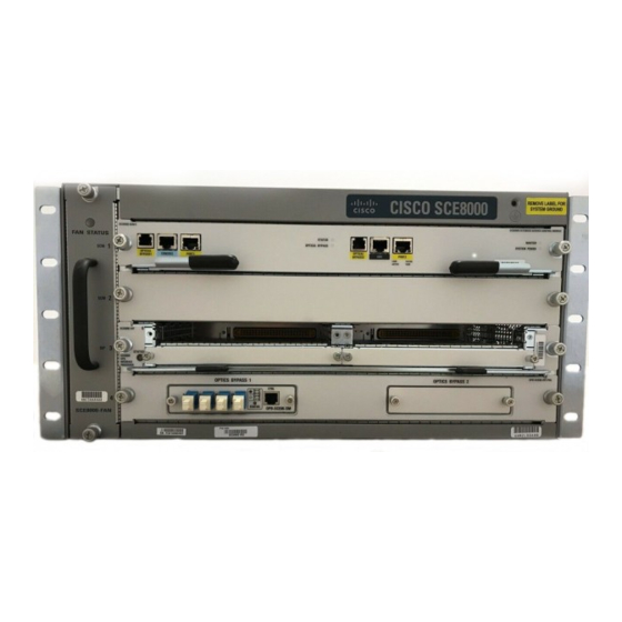
- Page 3 One Service Control Module (Cisco SCE 8000-SCM-E), with an optional redundant Service Control • Module (FRU). One SPA jacket module (Cisco SCE 8000-SIP), with either two or four SPA 10 GBE interface • modules (all FRU). Up to two optical bypass modules installed in the bottom slot of the chassis.
- Page 4 Removing and Replacing the Power Supply Removing and Replacing the Power Supply This section describes how to remove and install power supplies for the Cisco SCE 8000. In systems with redundant power supplies, you can replace the faulty supply while the system is Note operating.
- Page 5 Captive installation screws Grasp both power supply handles, as shown in Figure 9-2, and slide the power supply completely out of Step 5 the chassis. Figure 9-2 Handling the AC Power Supply Cisco SCE8000 10GBE Installation and Configuration Guide OL-26784-02...
- Page 6 Voltage is present on the backplane when the system is operating. To reduce risk of an electric shock, Warning keep hands and fingers out of the power supply bays and backplane areas. Statement 166 Cisco SCE8000 10GBE Installation and Configuration Guide OL-26784-02...
- Page 7 Loosen the captive installation screws on the power supply. (See Figure 9-3.) Use both hands to install and remove power supplies. Each PWR-2700-DC DC/4-input power supply Caution weighs 19.8 pounds (9.0 kg). Cisco SCE8000 10GBE Installation and Configuration Guide OL-26784-02...
- Page 8 Power supply ground is required. Install the PWR-2700-DC/4 power supply ground as described in this Step 1 procedure. The system ground connection with the PWR-2700-DC/4 power supply in a Cisco SCE 8000 is provided Note by the PWR-2700-DC/4 power supply ground. Additionally, you can connect a system (earth) ground.
- Page 9 Warning Statement 289 Because the power requirement of the Cisco SCE 8000 does not exceed 1350 W, it is not necessary to Note connect two pairs of input wires to each power supply. Should it be desired to connect two pairs of input wires, both pairs of input wires for one 2700W DC-input power supply must come from the same battery system (A feed);...
- Page 10 2-hole, standard barrel compression lug. The power supply ground studs, located below the terminal block, are also threaded 1/4-20 and require two 1/4-inch split-ring washers and two 1/4-20 hex nuts. Cisco SCE8000 10GBE Installation and Configuration Guide 9-10 OL-26784-02...
- Page 11 9. Step 10 Secure the terminal block cover using four screws and the terminal block barriers with two screws each. Cisco SCE8000 10GBE Installation and Configuration Guide 9-11 OL-26784-02...
- Page 12 INPUT OK LED is green • FAN OK LED is green • OUTPUT FAIL LED is not lit • If the LEDs indicate a power problem, see Identifying Startup Problems, page 8-7 Cisco SCE8000 10GBE Installation and Configuration Guide 9-12 OL-26784-02...
- Page 13 Chapter 9 Removal and Replacement Procedures Removing and Replacing the Fan Assembly Removing and Replacing the Fan Assembly This section describes how to remove and replace fan assemblies for the Cisco SCE 8000 chassis: Required Tools, page 9-13 • Removing the Fan Assembly, page 9-13 •...
- Page 14 Verify that the FAN STATUS LED is green. If the LED is red, one or more fans is faulty. • Cisco SCE8000 10GBE Installation and Configuration Guide 9-14 OL-26784-02...
- Page 15 CE 8K -MM Modules Slots 1-4 (top to bottom) Required Tools These tools are required to remove or install modules in the Cisco SCE 8000 chassis: 3/16-inch flat-blade screwdriver • Number 2 Phillips-head screwdriver • Wrist strap or other grounding device •...
- Page 16 If a second Cisco SCE 8000-SCM-E module is used, it must be installed in slot 2. The Cisco SCE 8000-SIP module must be installed in slot 3. • At the SCE# prompt, enter reload shutdown and press Enter to power down the Cisco SCE 8000 Step 2 platform before installing or removing any module.
- Page 17 SYSTEM POWER OPTICAL OPTICAL CONSOLE PORT1 PORT2 BYPASS1 BYPASS2 10/100/ LINK/ 10/100/ LINK/ 1000 ACTIVE 1000 ACTIVE M AS TE R SY ST EM PO W Captive installation Ejector lever screws Cisco SCE8000 10GBE Installation and Configuration Guide 9-17 OL-26784-02...
- Page 18 CONT ROL MODU LE SPA-1 X10G E-L-V 2 MAS TER STA TUS OPT ICA SYS TEM L BYP POW ER ASS 1 OP B-S CE 8K- EMI gasket Ejector lever fully extended Cisco SCE8000 10GBE Installation and Configuration Guide 9-18 OL-26784-02...
- Page 19 (0.040 inch [1 mm]) gap between the module EMI gasket and the module above it. (See Figure 9-12.) Do not press down too forcefully on the ejector levers. They can bend and be damaged. Caution Cisco SCE8000 10GBE Installation and Configuration Guide 9-19 OL-26784-02...
- Page 20 Note Removing a Module Before you remove a Cisco SCE 8000-SCM, you should first save the current configuration, if the current configuration should be preserved and duplicated on the new Cisco SCE 8000-SCM-E. (Use the copy running-config startup-config command.) This step saves time when bringing the module back online.
- Page 21 Chapter 9 Removal and Replacement Procedures Removing a Module At the SCE# prompt, enter reload shutdown and press Enter to power down the Cisco SCE 8000 Step 1 platform before installing or removing any module. Verify that the captive installation screws on all of the modules in the chassis are tight. This step assures Step 2 that the space created by the removed module is maintained.
- Page 22 SPA- 1X10 GE-L -V2 STA TUS OP TIC AL SCE8 000 EXTE NDED BYP ASS SERV ICE OP B-S CONT ROL MODU LE CE 8K- MAS TER SYS TEM POW ER Cisco SCE8000 10GBE Installation and Configuration Guide 9-22 OL-26784-02...
- Page 23 : 1500MHz cpu-2 SVR : 0x80900121 cpu-2 PVR : 0x80040202 cpu-2 freq : 1500MHz cpu (eeprom): 2.1, 1500MHz cpld-0 : 0xb20e cpld-1 : 0xb20e cpld-2 : 0xb20e cpld-0-ufm : 0xb803 Cisco SCE8000 10GBE Installation and Configuration Guide 9-23 OL-26784-02...
- Page 24 : SPA-1X10GE-L-V2 spa[1] : SPA-1XTENGE-XFP spa[2] : SPA-1X10GE-L-V2 spa[3] : SPA-1XTENGE-XFP ---------------- SCE8000 Chassis ---------------- product-num : CISCO7604 serial-num : FOX10420BKZ part-num : 73-9789-02 part-rev : A0 vid : V01 Cisco SCE8000 10GBE Installation and Configuration Guide 9-24 OL-26784-02...
- Page 25 Software package file: ftp://ftpserver/simba.pkg SCE8000 uptime is 9 minutes, 54 seconds After you verify installation of a Cisco SCE 8000 module and check connectivity, you must configure the module. For complete information on configuring the Cisco SCE 8000 platform, see the Cisco SCE8000 10GBE Software Configuration Guide.
- Page 26 If the Cisco SCE 8000-SCM module in slot 2 is to become the master Cisco SCE 8000-SCM module, the Cisco SCE 8000-SCM in slot 1 must be removed and the module on slot 2 must be moved and reinstalled in slot 1.
- Page 27 Adding a Cisco SCE 8000-SCM Module in Slot 2 Turn off the power before installing a Cisco SCE 8000-SCM module in slot 2 . If you add a second Cisco SCE 8000-SCM module while the system is running with a single Cisco SCE 8000-SCM module, the new module is held at reset until next system boot.
- Page 28 Installation and Upgrade Procedures for Dual Cisco SCE 8000-SCM Modules Downgrading Dual Cisco SCE 8000-SCM Modules Downgrading the system to a version earlier than 3.6.0 is not permitted on a system with dual Cisco SCE 8000-SCM modules. Perform the following steps to downgrade:...
- Page 29 This section provides information about the following tasks: When removing and replacing the 1-port 10 GBE SPAs, follow these guidelines: SPAs must be installed in pairs. The Cisco SCE 8000 supports the following SPA configurations: • Two SPAs inserted in subslots 0 and 1 –...
- Page 30 If you plan to install a SPA in a subslot that is not in use, you must first remove the SPA blank filler plate. Figure 9-16 Handling a SPA Metal carrier Printed circuit board Cisco SCE8000 10GBE Installation and Configuration Guide 9-30 OL-26784-02...
- Page 31 Statement 94 SPAs can be inserted or removed independently from the SIP. Removal of a SIP with installed SPAs is also supported. Cisco SCE8000 10GBE Installation and Configuration Guide 9-31 OL-26784-02...
- Page 32 To install a SPA in a SIP, see Figure 9-17 and do the following: At the SCE# prompt, enter reload shutdown and press Enter to power down the Cisco SCE 8000 Step 1 platform before installing or removing any module.
- Page 33 To remove a SPA from a SIP, see Figure 9-17 and do the following: At the SCE# prompt, enter reload shutdown and press Enter to power down the Cisco SCE 8000 Step 1 platform before installing or removing any module.
- Page 34 Cisco SCE 8000. Step 1 Install the new Cisco SCE 8000 platform in the rack. Power up the platform and perform necessary initial configuration. Step 2 Disconnect the cables connecting the optical bypass module to the old Cisco SCE 8000 platform.
- Page 35 Cisco SCE 8000 platform. Alternatively, it can be installed in an external mounting panel elsewhere in the rack. Connect the cables from the optical bypass module to the line interfaces of the new Cisco SCE 8000 Step 4 platform. See the “Optical Bypass Module Connectivity”...
- Page 36 Chapter 9 Removal and Replacement Procedures Replacing the Optical Bypass Module Without Disrupting Traffic on the Link Cisco SCE8000 10GBE Installation and Configuration Guide 9-36 OL-26784-02...