Epson ELPMB62 Installation Manual
Hide thumbs
Also See for ELPMB62:
- User manual (2 pages) ,
- Installation manual (142 pages) ,
- Installation manual (137 pages)
Table of Contents
Table of Contents

Related Manuals for Epson ELPMB62


Summary of Contents for Epson ELPMB62
- Page 1 Installation Guide...
-
Page 2: Safety Instructions
About This Installation Guide This guide describes how to mount the ultra-short-throw projectors listed below to a wall using the Epson® ELPMB62 wall mount. The following projectors are covered by this guide: • BrightLink® 1480Fi/1480Fi+ • BrightLink® 1485Fi/1485Fi+ Safety Instructions For your safety, read all the instructions in this guide before using the wall mount. - Page 3 Use M10 or 3/8 inch nuts and bolts and make sure to use appropriate wall anchors for your wall type. Nuts and bolts smaller than M10 or 3/8 inch could cause the wall mount to fall. Epson accepts no responsibility for any damage or injury caused by lack of wall strength or inadequate installation.
- Page 4 Warning Do not apply optical devices such as a magnifying glass or telescope to the laser light diffused from the touch unit. If such optical devices are applied, it could cause personal injury or fire. Do not look into the touch unit’s laser diffusion ports. This could cause injury to eyesight.
- Page 5 Installation Location • Before installing the projector, verify the power supply wiring for the installation location. • If you want to hide the projector power plug under the wall plate cover, make sure the power outlet is located in the empty space to the left or right of the wall plate. •...
- Page 6 • Before installing the touch unit, verify that the installation location meets the following conditions: • The touch unit can be secured to the surface with magnets or screws, or the optional touch unit bracket. • The surface is flat, smooth, and unwarped with no more than 0.2 inch (5 mm) of unevenness in any direction on the screen surface.
-
Page 7: Table Of Contents
Package Contents Specifications Connecting Devices Positioning the Projector Installation worksheet for projecting on a pre-installed wall-mounted board Installation worksheet for projecting on a plain wall Projection distance worksheets Diagonal image size and mounting position Distance from top of projected image to wall plate Installation measurement tables Installing the Projector Assemble the parts... - Page 8 Attaching the Covers Attach the wall plate cover and end cap Attach the cable cover to the projector Installing the Touch Unit Installing the touch unit on a whiteboard Install infrared deflectors along any obstacles Display the installation pattern Determine the installation position for the touch unit Install the touch unit Turn on the touch unit Adjust the angle...
-
Page 9: Package Contents
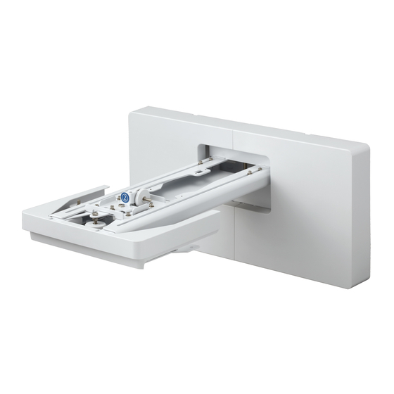
1 Package Contents Wall Mount Part name End cap 3-axis adjustment unit and slide plate (attached when shipped) Wall mount Wall plate Wall plate cover Hexagonal shaft... - Page 10 Hardware Shape Name Quantity Application M4 × 12 mm hexagon socket head cap bolt with For wall plate assembly washer/spring washer For 3-axis adjustment unit/wall mount installation For slide plate/projector installation M6 × 20 mm hexagon shoulder head bolt with For wall mount/wall plate installation washer/spring washer M6 ×...
- Page 11 Touch unit (included with BrightLink 1485Fi/1485Fi+) The following parts are packaged with your projector (BrightLink 1485Fi/1485Fi+) and are necessary when attaching the touch unit. When installing the touch unit on a non-magnetic screen or whiteboard, you will also need three M4 screws. Spacer for screw holes (×3) Touch unit Marker (x2)
- Page 12 Control pad (BrightLink 1485Fi/1485Fi+ only) The following parts are packaged with your projector (BrightLink 1485Fi/1485Fi+ only) and are necessary when attaching the control pad. When installing the control pad on a wall, you will also need four commercially available M4 × 20 mm screws. AC adapter Pen stand and cover Control pad...
-
Page 13: Specifications
2 Specifications Reference Item Specification Additional information page Wall mount weight (including the Approx. 20.3 lb — — 3-axis adjustment unit, slide plate, (9.2 kg) wall plate, wall plate cover, and end cap) Maximum load capacity 33.1 lb (15.0 kg) —... - Page 14 Wall plate The wall plate is in three pieces when shipped. Use the included M4 × 12 mm bolts (×5) to attach the separate pieces together before mounting the projector. See page 33 for instructions. 3.9 in. (99 mm) 3.9 in. (99 mm) 5.2 in.
- Page 15 Forward/backward slide adjustment range Arm slide adjustment range 15.1 in. (383 mm) Adjustment from 3-axis adjustment unit installation position By changing the installation position of the 3-axis adjustment unit to the front or back, you can adjust the installation position of the projector. When the screen size is less than 80 inches, install it at the position marked with a stamp on the mount arm.
- Page 16 Touch unit (included with BrightLink 1485Fi/1485Fi+) External dimensions and weight The touch unit weighs approximately 21.2 ounces (600 g). 16.6 in. (422 mm) Attached labels The touch unit is a Class 1 laser product that conforms to the IEC/EN60825-1:2014 standard. There are warning labels affixed to the touch unit to indicate that it is a Class 1 laser product.
- Page 17 Control pad (BrightLink 1485Fi/1485Fi+ only) External dimensions and weight The control pad weighs approximately 22.2 ounces (630 g). 6.9 in (174 mm) 1.4 in (36.5 mm) Cable routing holes When routing cables, use the positions ( ) in the following figure as the cable routing holes. Route the power cable along the groove on the back of the control pad (...
- Page 18 Pen stand external dimensions and weight The pen stand weighs approximately 3.3 ounces (93 g). 1.1 in 1.7 in 1.1 in 4.0 in (101.9 mm) (28.8 mm) (44.4 mm) (28.8 mm)
-
Page 19: Connecting Devices
3 Connecting Devices Make sure you have the power cord, computer cable, and other parts at the location where the wall mount is to be installed. Make sure you also have all necessary cables for the Touch Unit (if applicable) and other devices, such as a document camera or microphone, that you will connect to the projector. - Page 20 Connecting the Control Pad The Control Pad is included with the BrightLink Pro 1485Fi/Fi+. It provides a convenient alternative for turning on and controlling your projector. You must install the projector before installing the control pad. See page 80 for instructions.
-
Page 21: Positioning The Projector
1485Fi+ only) or 21:9 image up to 120 inches diagonally. This guide covers select image sizes. For other image sizes, use the Throw Distance Calculator at www.epson.com/support (U.S.), www.epson.ca/support (Canada), or www.epson.com.jm/support (Latin America). You can project onto a pre-installed whiteboard or directly onto a plain wall. -
Page 22: Installation Worksheet For Projecting On A Pre-Installed Wall-Mounted Board
Installation worksheet for projecting on a pre-installed wall-mounted board 11 in. (280 mm)—height of Distance from top of wall plate plus cover image area to temporary wall plate hole (d) 0.79 to 1.97 in. (20 to 50 mm) for 16:6* Required distance from top and 21:9, 0.22 to 1.97 in. - Page 23 ___ 4:3 XGA ___ 16:10 WXGA/WUXGA ___ 16:9 Widescreen ___ 16:6* ___ 21:9 *BrightLink 1485Fi/1485Fi+ only. If your desired aspect ratio does not match the native aspect ratio of your product, use the Throw Distance Calculator at www.epson.com/support (U.S.), www.epson.ca/support (Canada), or www.epson.com.jm (Latin America) to determine the correct measurements.
-
Page 24: Installation Worksheet For Projecting On A Plain Wall
If your desired aspect ratio does not match the native resolution of your product, use the Throw Distance Calculator at www.epson.com/support (U.S.), www.epson.ca/support (Canada), or www.epson.com.jm (Latin America) to determine the correct measurements. 3. Using the tables on pages 30 to 32, select the largest image size available for your ceiling height. -
Page 25: Projection Distance Worksheets
8. Add: Required distance from top of image area to bottom holes of wall plate (c) _____ (c) Height of image area (h) _____ (h) Distance from floor to bottom of image area (f ) _____ (f ) Height of wall plate plus cover + 11 inches _____ total If the total exceeds the ceiling height, you will need to reduce the image size or reduce... -
Page 26: Diagonal Image Size And Mounting Position
Diagonal image size and mounting position b + x In order to see the stamp and the numbers on the slider scale (b), you need to slide out the arm extension. When the diagonal image size is 80 inches or more, mount the 3-axis adjustment unit at the position marked with a stamp. -
Page 27: Distance From Top Of Projected Image To Wall Plate
Distance from top of projected image to wall plate The distance (c) from the top of the projected image to the bottom mounting holes on the wall plate is the number given when the vertical slide is set to the base position, as shown below. Match the notch on the wall mount to the position of the stamp on the wall plate. - Page 28 Measurements in Inches for 16:9 Aspect Ratio Distance from top Distance from top of image to of image to Diagonal Min. ceiling Image Image Min. projection Sliderscale bottom wall plate temporary wall image size (S) height* width (w) height (h) distance (a) mark (b) holes (c)
- Page 29 Measurements in Inches for 16:6 Aspect Ratio (BL 1485Fi/1485Fi+) Default Screen Position Screen Position max. (top) Distance from Distance from Distance from Distance from Diagonal Min. Image Image Min. proj. top of image top of image to top of image top of image to image ceiling...
- Page 30 Measurements in Inches for 16:10 Aspect Ratio Distance from top Distance from top of image to of image to Diagonal Min. ceiling Image Image Min. projection Sliderscale bottom wall plate temporary wall image size (S) height* width (w) height (h) distance (a) mark (b) holes (c)
- Page 31 Measurements in Inches for 4:3 Aspect Ratio Distance from top Distance from top of image to of image to Diagonal Min. ceiling Image Image Min. projection Sliderscale bottom wall plate temporary wall image size (S) height* width (w) height (h) distance (a) mark (b) holes (c)
- Page 32 Measurements in Inches for 21:9 Aspect Ratio Default Screen Position Screen Position max. (top) Min. Distance from Distance from Distance from Distance from Diagonal Min. Image Image projection top of image top of image to top of image top of image to image ceiling width...
-
Page 33: Installing The Projector
Nuts and bolts smaller than M10 or 3/8 inch could cause the wall mount to fall. ❏ Epson accepts no responsibility for any damage or injury caused by lack of wall strength or inadequate installation. Assemble the parts 1. - Page 34 2. Loosen the two screws with a cross-head screwdriver and remove the cable cover from the projector. 3. Align the 3-axis adjustment unit with the slide plate’s alignment mark. If the 3-axis adjustment unit is not aligned, loosen the M4 × 12 mm hexagon socket head cap bolt ( and correct the alignment ( ).
-
Page 35: Install The Wall Plate On The Wall
Install the wall plate on the wall 1. Determine the template sheet position and attach it to the wall. • Confirm where the beams or studs are within the wall that can support the projector and wall mount. • From the projection distance table, confirm the screen size (S), the distance between the projection image and wall plate bottom holes (c), and the distance between the projection image and temporary wall plate hole (d). - Page 36 3. Determine the position of the wall plate’s mounting holes. Use at least four mounting holes for proper balance. 4. Drill holes of the following diameters and depths. 3/8 inch anchor bolts: 0.39 in. (10 mm) Drill diameter M10 anchor bolts: 0.41 in. (10.5 mm) Pilot hole depth 1.8 in.
-
Page 37: Determine The Projection Distance And Pull Out The Mount Arm Slider
8. Insert commercially available M10 × 60 mm or 3/8 inch anchors into the holes and secure them in place. 9. Remove the temporary wall plate screw. Determine the projection distance and pull out the mount arm slider 1. Using the tables on pages 30 to 32, check the number for the slider measure (b). 2. -
Page 38: Route The Cables Through The Wall Mount Arm
Route the cables through the wall mount arm BrightLink 1485 Fi/Fi+: Make sure to route the Touch Unit connection cable through the wall mount arm. Route the Touch Unit connection cable so that the end that connects to the Touch Unit appears from the lower part of the wall mount as shown above. - Page 39 3. Insert the hexagonal shaft into the slot at the top of the wall plate ( 4. Insert the hexagonal shaft into the slot at the bottom of the wall plate ( Caution ❏ Make sure the Touch Unit connection cable is not wired into the wall with the other cables. ❏...
-
Page 40: Adjust The Vertical Slide Position Of The Arm
Adjust the vertical slide position of the arm 1. Adjust the vertical slide with the M8 hexagon bolt at the bottom of the wall mount ( ), or the hexagonal shaft at the top of the wall mount ( ). Start by aligning the notch on the arm with the alignment mark on the wall plate as shown below ( Tightening the M8 hexagon bolt lowers the wall mount, and loosening the bolt raises it ( Tightening the hexagonal shaft raises the wall mount, and loosening the shaft lowers it (... -
Page 41: Attach The Projector To The Wall Mount
Attach the projector to the wall mount Attach the 3-axis adjustment unit with the projector to the wall mount arm. • Decide which position you want to use for installing the 3-axis adjustment unit. Mount it at the stamp when the image is less than 80 inches diagonally, or at the stamp when the projected image is 80 inches or more diagonally. -
Page 42: Connect The Power Cord And Other Cables To The Projector
If you are planning to run the cables inside the wall, make sure you follow all local electrical codes. If you are running the cables outside the wall, use a cable management system to keep the cables from obstructing the image. An optional cable management system is available from Epson (part number ELPCK01). - Page 43 Attach a Mini PC or Stick PC if necessary You can secure a Mini PC or Stick PC to the left or the right side of the wall plate. Attach the Mini PC so that the air exhaust vents of the PC are not blocked. Install the PC so that the air exhaust vents are at the top and the air intake vents are at the bottom.
- Page 44 3. Rest the PC on the lip of the Mini PC plate and secure it with the band.
-
Page 45: Adjusting The Image
6 Adjusting the Image To ensure the best image quality, follow the steps below to adjust the projected image. You can also use the Auto Screen Adjustment feature to automatically adjust the image. See page 85 for more information. If possible, avoid adjustments with the Auto Screen Adjustment, Quick Corner, or Keystone functions of the projector. - Page 46 3. Select Screen Type. 4. Select the setting that matches the aspect ratio of your projection surface. If necessary, you can press the [Aspect] button on the remote control to temporarily change the aspect ratio as necessary to match the input signal. You will need to project content from a connected device in order to change the aspect ratio.
-
Page 47: Display The Test Pattern
Display the test pattern 1. Press the [Menu] button on the remote control or control panel. Remote Control Control Panel 2. Select Installation. 3. Select Setting Plate Installation Guide. 4. The installation guide and test pattern are displayed. Use these to monitor the image as you make the adjustments in steps Use adjustment dial 1 on the left side to adjust the horizontal roll Repeat steps... -
Page 48: Use Adjustment Dial 2 On The Top To Adjust The Horizontal Rotation
Use adjustment dial 2 on the top to adjust the horizontal rotation 1. Loosen the screw to unlock the adjustment dials ( 2. Turn the adjustment dials to adjust the horizontal rotation ( 3. After you finish making all of the adjustments in steps , tighten the screw you loosened in Use adjustment dial 3 on the front to adjust the vertical tilt 1. -
Page 49: Adjust The Horizontal Slide
Adjust the horizontal slide 1. Loosen the M4 × 12 mm hexagon socket head cap bolt ( 2. Adjust the slider for the slide plate ( 3. After you finish making all of the adjustments in steps , tighten the M4 × 12 mm hexagon socket head cap bolt you loosened in Adjust the forward/backward slide 1. -
Page 50: Adjust The Vertical Slide
Adjust the vertical slide 1. Loosen the M6 × 20 mm hexagon shoulder bolt ( 2. Adjust the vertical slide with the M8 hexagon bolt at the bottom of the wall mount, or the hexagonal shaft at the top of the wall mount ( Tightening the M8 hexagon bolt lowers the wall mount, and loosening the bolt raises it. -
Page 51: Turn Off The Display Of The Test Pattern
Turn off the display of the test pattern Press the [Esc] button on the remote control or control panel to turn off the test pattern. Warning Tighten all screws firmly. Otherwise, the projector or wall mount may fall and cause personal injury or property damage. -
Page 52: Attaching The Covers
7 Attaching the Covers Attach the wall plate cover and end cap If you need to use a security cable, make sure you attach it before installing the wall plate cover. See page 92 for instructions. 1. Attach the left wall plate cover. 2. -
Page 53: Attach The Cable Cover To The Projector
3. Attach the end cap to the mount arm. 4. If you want to cover the groove in the mount arm, attach the masking sticker as shown. Attach the cable cover to the projector Attach the cable cover ( ) and use a cross-head screwdriver to tighten the screws (x2) and secure the cable cover (... - Page 54 Caution Only a specialist should remove or reinstall the projector, including for maintenance and repairs. Refer to your online User’s Guide for your projector for instructions on maintenance and repairs. Warning ❏ Never loosen the bolts and nuts after installation. If you find any loose screws, tighten them firmly.
-
Page 55: Installing The Touch Unit
8 Installing the Touch Unit Before installing the touch unit, make sure you install the projector and adjust the projected image (see page 33). You also need to calibrate the interactive pen(s) before you install the touch unit (see the online User’s Guide for more information). -
Page 56: Installing The Touch Unit On A Whiteboard
Installing the touch unit on a whiteboard Follow the steps below to install the touch unit on a whiteboard. Some menus may differ slightly from the illustrations, but the installation instructions are the same. ❏ There are magnets built in to the back of the touch unit. Typically, the touch unit should be installed by attaching the magnets to the screen or whiteboard. -
Page 57: Display The Installation Pattern
Turn on the projector Press the power button on the remote control or the projector. Display the installation pattern 1. Press the [Menu] button on the remote control or control panel. Remote Control Control Panel 2. Select Installation. 3. Select Touch Unit. 4. -
Page 58: Determine The Installation Position For The Touch Unit
The Installation pattern is displayed on the projected image. Determine the installation position for the touch unit 1. Mark the following installation positions: • ): The center line of the installation pattern. • ): 0.79 to 1.97 inches (20 to 50 mm) from the top edge of the projected image for 16:6/21:9 aspect ratio images or 0.22 to 1.97 inches (5.7 to 50 mm) from the top edge of the projected image for all others;... - Page 59 2. For non-magnetic boards or screens, attach the template sheet to the board. Line up the pattern on the bottom of the sheet with the top of the projected pattern. Drill two holes where indicated and remove the template sheet.
-
Page 60: Install The Touch Unit
Install the touch unit • For magnetic boards, place the back of the touch unit on the screen surface to secure it. Caution When installing the touch unit on a magnetic surface, be careful not to trap your fingers or any other part of your body between the magnets and the installation surface. - Page 61 Secure the touch unit with two (2) M4 screws (not included). 0.8 in. (20 mm) Re-attach the rubber caps.
-
Page 62: Turn On The Touch Unit
Turn on the touch unit 1. Connect the touch unit connection cable from the projector to the port on the touch unit. Make sure the arrows on the port and cable are lined up. Make sure you use the supplied touch unit connection cable. Operations are not possible with a commercially available cable. -
Page 63: Adjust The Angle
5. Set Power to On. The touch unit power turns on and the power light turns blue. Warning Do not look into the projector’s projection window or the touch unit’s laser diffusion ports (located on the bottom of the touch unit); this could cause injury to eyesight. When Power is set to On, the touch unit automatically powers up when the projector is turned on. - Page 64 1. Press the [Menu] button on the remote control or control panel. Remote Control Control Panel 2. Select Installation. 3. Select Touch Unit. 4. Select Touch Unit Setup. If you're using multiple projectors and the HDMI Out Setting option in the Multi- Projection menu is set to Process Out, follow the on-screen instructions to turn off the Power setting for the touch unit on the next projector you set up.
- Page 65 5. Select Installing the Touch Unit without the bracket. 6. Attach the two markers to the positions shown on the projected screen. Match the positions so that the crosses ( ) overlap with the points ( ) on the marker positions. Move the marker over the projected cross until the lines of the cross align with the lines on the marker.
- Page 66 Attach the markers to the projection screen as follows: • For magnetic screens: Place the bottom of the markers onto the screen with the thinner end of the marker facing the touch unit. • For non-magnetic screens: Use the supplied tape to secure the markers with the thinner side of the marker facing the touch unit.
- Page 67 9. Touch each of the four yellow circles on the screen and verify that the gray touch indicators appear in the correct position. Finger touch operations may not function correctly if you are wearing bandages, artificial nails, nail polish, or anything else that may obstruct your fingers. If the gray indicators do not appear where you touched the screen, you need to manually adjust the touch unit alignment.
-
Page 68: Installing The Touch Unit Above A Whiteboard
Installing the touch unit above a whiteboard Follow the steps below to use the optional touch unit bracket to install the touch unit above the frame of a whiteboard. Some menus may differ slightly from the illustrations, but the installation instructions are the same. -
Page 69: Turn On The Projector
Turn on the projector Press the power button on the remote control or the projector. Display the installation pattern 1. Press the [Menu] button on the remote control or control panel. Remote Control Control Panel 2. Select Installation. 3. Select Touch Unit. 4. -
Page 70: Determine The Installation Position For The Bracket
The Installation pattern is displayed on the projected image. Determine the installation position for the bracket Align the bottom of the bracket template sheet with the top of the projection surface and attach the sheet to the wall. The touch unit must be installed above the image area. -
Page 71: Drill Holes For The Bracket
Drill holes for the bracket If possible, drill holes at the four points labeled Main on the template sheet. If you’re unable to use the points labeled Main, you can secure the bracket at the points labeled Sub. Make sure you secure the bracket at four points (two on the left and two on the right) for proper balance. - Page 72 4. Slide the front of the bracket until the lower edge touches the projection surface. ❏ If the distance from the wall to the surface of the whiteboard is greater than 2 inches (51 mm), you must install the touch unit on the whiteboard. ❏...
- Page 73 6. Remove the rubber caps (×2) from the front of the touch unit. 7. Secure the touch unit to the bracket with the M4 × 25 mm bolts (×2) supplied. Caution When attaching the touch unit to the bracket, be careful not to trap your fingers or any other part of your body between the magnets and the bracket.
-
Page 74: Turn On The Touch Unit
Turn on the touch unit 1. Connect the touch unit connection cable that is connected to the projector to the port on the Touch Unit. Make sure you use the supplied touch unit connection cable. Operations are not possible with a commercially available cable. 2. -
Page 75: Adjust The Angle
5. Set Power to On. The touch unit power turns on and the indicator light turns blue. Warning Do not look into the projector’s projection window or the touch unit’s laser diffusion ports (located on the bottom of the touch unit); this could cause injury to eyesight. When Power is set to On, the touch unit automatically powers up the next time the projector is turned on. - Page 76 1. Press the [Menu] button on the remote control or control panel. Remote Control Control Panel 2. Select Installation. 3. Select Touch Unit. 4. Select Touch Unit Setup. If you're using multiple projectors and the HDMI Out Setting option in the Multi- Projection menu is set to Process Out, follow the on-screen instructions to turn off the Power setting for the touch unit on the next projector you set up.
- Page 77 5. Select Installing the Touch Unit with the bracket. 6. Loosen the adjustment screw at the top of the bracket until it stops turning. Make sure you stop loosening the screw as soon as it stops turning. Continuing to turn the screw may remove it from the bracket.
- Page 78 7. Attach the two markers to the positions shown on the projected screen. Match the positions so that the crosses ( ) overlap with the points ( ) on the marker positions. Move the marker over the projected cross until the lines of the cross align with the lines on the marker. Attach the markers to the projection screen as follows: •...
- Page 79 10. Touch each of the four yellow circles on the screen and verify that the gray touch indicators appear in the correct position. Finger touch operations may not function correctly if you are wearing bandages, artificial nails, nail polish, or anything else that may obstruct your fingers. If the gray indicators do not appear where you touched the screen, you need to manually adjust the touch unit alignment.
-
Page 80: Installing The Control Pad And Pen Stand
9 Installing the Control Pad and Pen Stand (BrightLink 1485Fi/1485Fi+ Only) You must install the projector before installing the control pad and pen stand. Caution The control pad should only be connected to the BrightLink 1485Fi/1485Fi+. Do not connect the control pad to any other projectors. -
Page 81: Attach The Control Pad
Connect the power cable Connect the power cable and route it down the groove on the back of the control pad. Attach the control pad Attach the control pad with commercially available M4 × 20 mm screws (×4). Warning ❏ Make sure the screws are not angled. -
Page 82: Connect The Power Cable
Secure the AC adapter Secure the AC adapter holder to the wall using M4 screws (×4) Slide the AC adapter into the holder and connect the power cable. Connect the projector cables to the control pad See the connection example on page 19 for details. -
Page 83: Attach The Front Cover
Attach the front cover... -
Page 84: Install The Pen Stand
Install the pen stand You can secure the pen stand with commercially-available M4 screws (not included) or the attached magnets. 1. Secure the pen stand: • If your whiteboard is magnetic, you can use the magnets on the back of the pen stand to secure it. You need to leave a gap of at least 3.9 inches (100 mm) between the pen stand and the left or right side of the projected image or the touch feature may not function properly. -
Page 85: Appendix
For details, see the online User's Guide or visit: U.S.: www.epson.com/support/brightlinkdownloads Canada: www.epson.ca/support/brightlinkdownloads Latin America: www.epson.com.jm/support Using Auto Screen Adjustment If possible, avoid adjustments with the Auto Screen Adjustment, Quick Corner, or Keystone functions of the projector. Doing so may result in a reduction in image quality and pen or finger touch calibration. - Page 86 2. Press the [Menu] button on the remote control or control panel. Remote Control Control Panel 3. Select Installation. 4. Select Auto Screen Adjustment. 5. Loosen all of the adjustment dials and screws.
- Page 87 6. Adjust the projector position so that the corner markers are completely within the highlighted areas in the corners of the image. 7. Tighten any adjustment dials and screws that you previously loosened. Warning Tighten all screws firmly. Otherwise, the projector or wall mount may fall and cause personal injury or property damage.
-
Page 88: Making Additional Screen Adjustments
Making Additional Screen Adjustments If possible, avoid adjustments with the Auto Screen Adjustment, Quick Corner, or Keystone functions of the projector. Doing so may result in a reduction in image quality and pen or finger touch calibration. Correcting the Image Shape on a Curved Screen If you are projecting on a curved screen, adjust the Arc Correction setting to correct the image shape. - Page 89 5. Select the area that you want to correct. 6. Use the arrow buttons on the remote control or control panel to change the shape of the selected area. 7. Repeat steps 5 and 6 to adjust any additional areas. Correcting the Corner Shape You can adjust the shape of the image corners with the Quick Corner setting.
- Page 90 4. Select Quick Corner. 5. Select the corner that you want to correct. 6. Use the arrow buttons on the remote control or control panel to change the shape of the selected corner. 7. Repeat steps 5 and 6 to adjust any additional corners. Correcting the Image Shape at Individual Points You can adjust the image at specific points with the Point Correction setting.
- Page 91 3. Select Geometry Correction. 4. Select Point Correction. 5. Select the point on the grid that you want to correct. 6. Use the arrow buttons on the remote control or control panel to change the shape of the selected point. 7.
-
Page 92: Attaching A Security Cable
If your projector came with a product- specific installation guide or an installation leave-behind list, use that list instead of this one. The accessories included with the projector vary by model and region. © 2019 Epson America, Inc., 11/19 CPD-58124...