
Related Manuals for Siemens AVS75.39 Series


Summary of Contents for Siemens AVS75.39 Series
- Page 1 Infrastructure & Cities Albatros RVS43.345 Boiler controller AVS75.. User Manual Edition 1.2 Controller series B CE1U2354en_021 Building Technologies 2013-09-02...
- Page 2 Siemens Switzerland Ltd. Infrastructure & Cities Sector Building Technologies Division Gubelstrasse 22 6301 Zug Switzerland Tel. +41 41-724 24 24 © 2007-2013 Siemens Switzerland Ltd. www.siemens.com/sbt Subject to change 2 / 239 Siemens User manual RVS43.345 CE1U2354en_021 Building Technologies 2013-09-02...
-
Page 3: Table Of Contents
Configuration ..................149 6.18 LPB ....................183 6.19 Fault ....................187 6.20 Maintenance/special operation ............188 6.21 Configuring the extension modules ............ 192 6.22 Input/output test ................. 197 3 / 239 Siemens User manual RVS43.345 CE1U2354en_021 Building Technologies Contents 2013-09-02... - Page 4 Extension module AVS75.370 ............227 Extension module AVS75.39x ............229 Sensor characteristics................ 230 8.4.1 NTC 1 k ..................... 230 8.4.2 NTC 10 k ................... 231 8.4.3 Pt1000 ....................231 Index ......................232 4 / 239 Siemens User manual RVS43.345 CE1U2354en_021 Building Technologies Contents 2013-09-02...
-
Page 5: Summary
Room unit, for wiring, with backlit display QAA78.610 Room unit, wireless QAA55.110 Room unit basic, wired QAA58.110 Room unit basic, RF. AVS16.290 Power section AVS71.390 Radio module AVS14.390 Radio repeater AVS13.399 Wireless outside sensor 5 / 239 Siemens User manual RVS43.345 CE1U2354en_021 Building Technologies Summary 2013-09-02... -
Page 6: Type Summary
Type summary 1.1.1 Topology Wired room units Wireless room units 6 / 239 Siemens User manual RVS43.345 CE1U2354en_021 Building Technologies Summary 2013-09-02... -
Page 7: The Communication Choices In Detail
1.1.2 The communication choices in detail * Only with OZW672 PSTN Public switched telephone network WLAN Wireless LAN Global System for Mobile Communications 7 / 239 Siemens User manual RVS43.345 CE1U2354en_021 Building Technologies Summary 2013-09-02... -
Page 8: Safety Notes
Power cables must be clearly separated from low-voltage cables (sensors) observing a distance of at least 100 mm Mounting location Boiler Control panel Housing for wall mounting 8 / 239 Siemens User manual RVS43.345 CE1U2354en_021 Building Technologies Safety notes 2013-09-02... - Page 9 Dimensions and drilling plan Dimensions in mm RVS43.345 180.7 120.7 51.7 2359Z10 Total height required Connectors with min. 70 mm tongues Connectors without tongues, min. 60 mm 9 / 239 Siemens User manual RVS43.345 CE1U2354en_021 Building Technologies Mounting and installation 2013-09-02...
-
Page 10: Connection Terminals Rvs43.345
3.2.1 Connection terminals RVS43.345 Mains voltage connections PCB diagram Terminal markings RVS43.345 10 / 239 Siemens User manual RVS43.345 CE1U2354en_021 Building Technologies Mounting and installation 2013-09-02... - Page 11 Y2 / QX2 1. heating circuit mixing valve closing/ 2. multifunctional output Phase 1st multifunctional output AGP8S.03G/109 Inverted signal from QX1 1. Multifunctional output / 2nd burner stage 11 / 239 Siemens User manual RVS43.345 CE1U2354en_021 Building Technologies Mounting and installation 2013-09-02...
- Page 12 Ground B1 / BX3 Flow temperature sensor HC1/ AGP4S.02S/109 Multifunctional sensor input 3 Ground Multifunctional sensor input 1 AGP4S.02F/109 Ground Multifunctional sensor input 2 AGP4S.02F/109 Ground 12 / 239 Siemens User manual RVS43.345 CE1U2354en_021 Building Technologies Mounting and installation 2013-09-02...
-
Page 13: Extension Module Avs75.370
Additional modules are connected from socket X50 of the first module to socket X50 of the next module. Up to 3 extension modules can be connected to the basic module. 13 / 239 Siemens User manual RVS43.345 CE1U2354en_021 Building Technologies... -
Page 14: Connection Terminals Avs75.370
3.3.1 Connection terminals AVS75.370 Mains voltage connections Diagram for AVS75.370 Terminal markings AVS75.370 = module 1 = module 2 = module 3 14 / 239 Siemens User manual RVS43.345 CE1U2354en_021 Building Technologies Mounting and installation 2013-09-02... - Page 15 "Function extension module 1" Operating line 7300 "Function extension module 2" Operating line 7375 "Function extension module 3" Operating line 7450 are used to define usage of the respective module. 15 / 239 Siemens User manual RVS43.345 CE1U2354en_021 Building Technologies Mounting and installation...
-
Page 16: Extension Module Avs75.39X
Additional modules are connected using connector X30 on the first module to connector X50 for the next module. Up to 3 extension modules can be connected to the basic module. 16 / 239 Siemens User manual RVS43.345 CE1U2354en_021 Building Technologies... -
Page 17: Connection Terminals Avs75.390
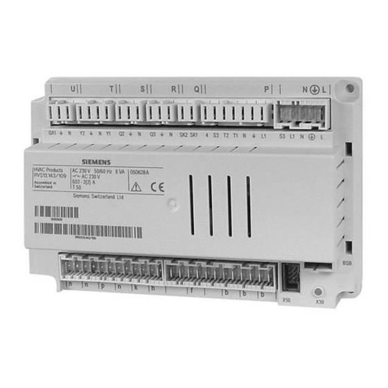
3.4.1 Connection terminals AVS75.390 Mains voltage connections Diagram AVS75.390 Terminal markings AVS75.390 = module 1 = module 2 = module 3 17 / 239 Siemens User manual RVS43.345 CE1U2354en_021 Building Technologies Mounting and installation 2013-09-02... - Page 18 Connection to basic unit or first AVS82.490/109 extension module BX21 Assignment according to function AGP4S.02F/109 Ground BX22 Assignment according to function AGP4S.02F/109 Ground Digital/DC 0...10 V input AGP4S.02F/109 Ground 18 / 239 Siemens User manual RVS43.345 CE1U2354en_021 Building Technologies Mounting and installation 2013-09-02...
-
Page 19: Connection Terminals Avs75.391
3.4.2 Connection terminals AVS75.391 Mains voltage connections Diagram AVS75.391 = module 1 19 / 239 Siemens User manual RVS43.345 CE1U2354en_021 Building Technologies Mounting and installation 2013-09-02... - Page 20 "Function extension module 1" Operating line 7300 "Function extension module 2" Operating line 7375 "Function extension module 3" Operating line 7450 are used to define usage of the respective module. 20 / 239 Siemens User manual RVS43.345 CE1U2354en_021 Building Technologies Mounting and installation...
-
Page 21: Commissioning
For detailed diagnostics of the plant, check menus "Diagnostics heat generation" and "Diagnostics consumers". Basic unit RVS43.345 Checking the LEDs LED off: No power LED on Ready to operate LED flashes Local errors 21 / 239 Siemens User manual RVS43.345 CE1U2354en_021 Building Technologies Commissioning 2013-09-02... -
Page 22: Overview Of Settings
2nd phase off 24:00 00:00 24:00 hh:mm 3rd phase on 24:00 00:00 24:00 hh:mm 3rd phase off 24:00 00:00 24:00 hh:mm Default values No ¦ Yes 22 / 239 Siemens User manual RVS43.345 CE1U2354en_021 Building Technologies Overview of settings 2013-09-02... - Page 23 °C Flow temp setpoint room stat Line 740 Line 741 °C Swi-on ratio room stat Room influence Room temp limitation / 0.5 °C Boost heating °C 23 / 239 Siemens User manual RVS43.345 CE1U2354en_021 Building Technologies Overview of settings 2013-09-02...
- Page 24 Cooling limit at OT °C Lock time at end of heating Summer comp start at OT °C Summer comp end at OT °C Summer comp setp increase °C 24 / 239 Siemens User manual RVS43.345 CE1U2354en_021 Building Technologies Overview of settings 2013-09-02...
- Page 25 1091 Optimum stop control max 1094 Heat up gradient Min/K 1100 Reduced setp increase start / -30 °C 1101 Reduced setp increase end Line 1100 °C 25 / 239 Siemens User manual RVS43.345 CE1U2354en_021 Building Technologies Overview of settings 2013-09-02...
- Page 26 Flow temp setpoint max Line 1340 °C 1342 Flow temp setpoint room stat Line 1340 Line 1341 °C 1344 Swi-on ratio room stat 1350 Room influence 26 / 239 Siemens User manual RVS43.345 CE1U2354en_021 Building Technologies Overview of settings 2013-09-02...
- Page 27 24h/day ¦ Time programs HCs ¦ Time program 4/DHW 1630 Charging priority MC shifting, PC absolute Absolute ¦ Shifting ¦ None ¦ MC shifting, PC absolute 1640 Legionella function Fixed weekday 27 / 239 Siemens User manual RVS43.345 CE1U2354en_021 Building Technologies Overview of settings 2013-09-02...
- Page 28 DHW charging priority No ¦ Yes 1975 Excess heat draw Off ¦ On 1978 With buffer No ¦ Yes 1980 With prim contr/system pump No ¦ Yes 28 / 239 Siemens User manual RVS43.345 CE1U2354en_021 Building Technologies Overview of settings 2013-09-02...
- Page 29 Modulating Tn 2235 Modulating Tv 2240 Switching differential boiler °C 2241 Burner running time min 2250 Pump overrun time 2260 Prot boil startup consumers Off ¦ On 29 / 239 Siemens User manual RVS43.345 CE1U2354en_021 Building Technologies Overview of settings 2013-09-02...
- Page 30 °C 3562 Return influence consumers Off ¦ On 3570 Actuator running time 3571 Mixing valve Xp °C 3572 Mixing valve Tn 3590 Temp differential min °C 30 / 239 Siemens User manual RVS43.345 CE1U2354en_021 Building Technologies Overview of settings 2013-09-02...
- Page 31 / 60 °C 3862 Impact evaporation superv To own collector pumps pump ¦ On both collector pumps On own collector 3870 Pump speed min Line 3871 31 / 239 Siemens User manual RVS43.345 CE1U2354en_021 Building Technologies Overview of settings 2013-09-02...
- Page 32 Return setpoint min OEM °C 4158 Flow influence return ctrl Off ¦ On 4163 Actuator running time 4164 Mixing valve Xp °C 4165 Mixing valve Tn 32 / 239 Siemens User manual RVS43.345 CE1U2354en_021 Building Technologies Overview of settings 2013-09-02...
- Page 33 With B42/B41 With B4 ¦ With B42/B41 DHW storage tank 5010 Charging Several times/day Once/day ¦ Several times/day 5020 Flow setpoint boost °C 5021 Transfer boost °C 33 / 239 Siemens User manual RVS43.345 CE1U2354en_021 Building Technologies Overview of settings 2013-09-02...
- Page 34 Min start temp diff Q33 °C 5149 Start delay Q33 Legionella funct mixing pump 5160 With charging and duration Off ¦ With charging ¦ With charging and duration 34 / 239 Siemens User manual RVS43.345 CE1U2354en_021 Building Technologies Overview of settings 2013-09-02...
- Page 35 1-stage 1-stage ¦ 2-stage ¦ Modulating 3-position ¦ Modulating UX ¦ Without boiler sensor 5772 Burner prerun time - - - - - - / 0 35 / 239 Siemens User manual RVS43.345 CE1U2354en_021 Building Technologies Overview of settings 2013-09-02...
- Page 36 Input value 2 H3 1000 5966 Function value 2 H3 -100 5967 Temperature sensor H3 None None ¦ Solar flow sensor B63 ¦ Solar return sensor B64 36 / 239 Siemens User manual RVS43.345 CE1U2354en_021 Building Technologies Overview of settings 2013-09-02...
- Page 37 2 ¦ With input H22 module 3 ¦ With input H3 6180 Water pressure 3 max / 0.0 10.0 6181 Water pressure 3 min / 0.0 10.0 6182 Water press 3 critical min / 0.0 10.0 37 / 239 Siemens User manual RVS43.345 CE1U2354en_021 Building Technologies Overview of settings 2013-09-02...
- Page 38 Manual source lock Locally Local ¦ Segment 6625 DHW assignment All HCs in system Local HCs ¦ All HCs in segment ¦ All HCs in system 38 / 239 Siemens User manual RVS43.345 CE1U2354en_021 Building Technologies Overview of settings 2013-09-02...
- Page 39 / 60 / 100 65535 7043 Burn starts since maint 65535 7044 Maintenance interval months 7045 Time since maintenance months 7053 Flue gas temp limit °C 39 / 239 Siemens User manual RVS43.345 CE1U2354en_021 Building Technologies Overview of settings 2013-09-02...
- Page 40 7317 Funct value 2 H2 module 1 -100 7318 Temp sensor H2 module 1 None None ¦ Solar flow sensor B63 ¦ Solar return sensor B64 40 / 239 Siemens User manual RVS43.345 CE1U2354en_021 Building Technologies Overview of settings 2013-09-02...
- Page 41 None ¦ Multifunctional ¦ Heating circuit 1 ¦ Heating circuit 2 ¦ Heating circuit 3 ¦ Return temp controller ¦ Solar DHW ¦ Primary contr/system pump ¦ DHW primary controller ¦ Instantaneous water heater ¦ Return temp contr cascade ¦ Cooling circuit 1 ¦ Heating circ/cooling circ 1 ¦ Solid fuel boiler 41 / 239 Siemens User manual RVS43.345 CE1U2354en_021 Building Technologies...
- Page 42 7403 Temp sensor H21 module 2 None None ¦ Solar flow sensor B63 ¦ Solar return sensor B64 7406 Function input H22 module 2 Ditto 7396 42 / 239 Siemens User manual RVS43.345 CE1U2354en_021 Building Technologies Overview of settings 2013-09-02...
- Page 43 Collector sensor 2 B61 ¦ Solar flow sensor B63 ¦ Solar return sensor B64 ¦ DHW outlet sensor B38 ¦ Solid fuel boil ret sens 7458 Sensor input BX22 module 3 Ditto 7457 43 / 239 Siemens User manual RVS43.345 CE1U2354en_021 Building Technologies Overview of settings...
- Page 44 K18 ¦ Collector pump 2 Q16 ¦ Instant WH pump Q34 ¦ Solid fuel boiler pump Q10 7499 Sign logic out UX21 module3 Standard Standard ¦ Inverted 44 / 239 Siemens User manual RVS43.345 CE1U2354en_021 Building Technologies Overview of settings 2013-09-02...
- Page 45 7820 Sensor temp BX1 -28.0 °C 7821 Sensor temp BX2 -28.0 °C 7830 Sensor temp BX21 module 1 °C 7831 Sensor temp BX22 module 1 °C 45 / 239 Siemens User manual RVS43.345 CE1U2354en_021 Building Technologies Overview of settings 2013-09-02...
- Page 46 0V ¦ 230V 7881 1st burner stage E1 0V ¦ 230V 7884 SLT error message L1 0V ¦ 230V 7950 Input EX21 module 1 0V ¦ 230V 46 / 239 Siemens User manual RVS43.345 CE1U2354en_021 Building Technologies Overview of settings 2013-09-02...
- Page 47 Hours run 2nd stage 65535 8333 Start counter 2nd stage 199999 8505 Speed collector pump 1 8506 Speed solar pump ext exch 8507 Speed solar pump buffer 47 / 239 Siemens User manual RVS43.345 CE1U2354en_021 Building Technologies Overview of settings 2013-09-02...
- Page 48 °C 8744 Flow temp setpoint 1 140.0 °C 8749 Room thermostat 1 No demand No demand ¦ Demand 8751 Cooling circuit pump 1 Off ¦ On 48 / 239 Siemens User manual RVS43.345 CE1U2354en_021 Building Technologies Overview of settings 2013-09-02...
- Page 49 Instant WH setpoint °C 8875 Flow temp setp VK1 °C 8885 Flow temp setp VK2 °C 8895 Flow temp setp swimming pool °C 8900 Swimming pool temp °C 49 / 239 Siemens User manual RVS43.345 CE1U2354en_021 Building Technologies Overview of settings 2013-09-02...
- Page 50 Relay output QX21 module 3 Off ¦ On 9057 Relay output QX22 module 3 Off ¦ On 9058 Relay output QX23 module 3 Off ¦ On 50 / 239 Siemens User manual RVS43.345 CE1U2354en_021 Building Technologies Overview of settings 2013-09-02...
-
Page 51: The Settings In Detail
Up to 8 independent holiday periods can be entered. Important: The holiday program can only be used in Automatic mode. 51 / 239 Siemens User manual RVS43.345 CE1U2354en_021 Building Technologies The settings in detail 2013-09-02... -
Page 52: Heating Circuits
Heating mode without time program. Protective functions active. Automatic summer / winter changeover (ECO functions) and automatic 24-hour heating limit are inactive in Comfort mode. 52 / 239 Siemens User manual RVS43.345 CE1U2354en_021 Building Technologies The settings in detail 2013-09-02... - Page 53 The Comfort setpoint max limits the uppermost adjustable Comfort setpoint. The Comfort setpoint cannot be set to value that is higher than the defined value on the corresponding room unit or operating lines. 53 / 239 Siemens User manual RVS43.345 CE1U2354en_021 Building Technologies...
- Page 54 There should be no thermostatic radiator valves in the reference room (mounting location of room temperature sensor) (if such valves are present, they must be set to their fully open position). 54 / 239 Siemens User manual RVS43.345 CE1U2354en_021 Building Technologies...
- Page 55 To give consideration to the building’s thermal dynamics, the outside temperature is attenuated Example: TAged °C SWHG SWHG -1 °C SWHG Summer/winter heating limit TAged Attenuated outside temperature Temperature Days 55 / 239 Siemens User manual RVS43.345 CE1U2354en_021 Building Technologies The settings in detail 2013-09-02...
- Page 56 The function is not active in operating mode "Continuously Comfort temperature" The display shows ECO. To give consideration to the building’s thermal dynamics, the outside temperature is attenuated 56 / 239 Siemens User manual RVS43.345 CE1U2354en_021 Building Technologies The settings in detail...
- Page 57 Setting Yes / No in operating lines 733, 1033 or 1333 Room temperature setpoint Actual outside temperature TAgem Composite outside temperature 24-hour heating limit Temperature Time of day 57 / 239 Siemens User manual RVS43.345 CE1U2354en_021 Building Technologies The settings in detail 2013-09-02...
- Page 58 The flow temperature can be adapted based on demand if the flow temperature setpoint is preset using parameter setting (line 742/1042/1342). - - - Setting "- - -" deactivates the function. 1...99% Function is activated. 58 / 239 Siemens User manual RVS43.345 CE1U2354en_021 Building Technologies The settings in detail 2013-09-02...
- Page 59 There should be no thermostatic radiator valves in the reference room (mounting location of the room sensor). (If such valves are present, they must be set to their fully open position). 59 / 239 Siemens User manual RVS43.345 CE1U2354en_021 Building Technologies...
- Page 60 Boost heating can be provided with or without room sensor. °C DTRSA Room temperature setpoint Actual value of the room temperature DTRSA Increase of room temperature setpoint 60 / 239 Siemens User manual RVS43.345 CE1U2354en_021 Building Technologies The settings in detail 2013-09-02...
- Page 61 Optimum stop control advances changeover of the temperature level to achieve Comfort setpoint -1/4 °C at the switching times. The setting "Optimum stop control max" limits the period of precontrol. 61 / 239 Siemens User manual RVS43.345 CE1U2354en_021 Building Technologies...
- Page 62 Comfort setpoint. TRwA1 TRwA2 TRwA1 Reduced setp increase start TRwA2 Reduced setp increase end Comfort setpoint Reduced room temperature setpoint TAgem The composite outside temperature TAgem 62 / 239 Siemens User manual RVS43.345 CE1U2354en_021 Building Technologies The settings in detail 2013-09-02...
- Page 63 Function "Overtemperature protection for pump heating circuits" ensures that the energy supply for pump heating circuits corresponds to the demand from the heating curve by activating / deactivating the pump. 63 / 239 Siemens User manual RVS43.345 CE1U2354en_021 Building Technologies...
- Page 64 It is the required of the I-portion to undertake the same manipulated variable change at the given input signal (controlled variable), as immediately provided by the P-portion. The smaller the Tn the larger/faster the slope. 64 / 239 Siemens User manual RVS43.345 CE1U2354en_021 Building Technologies...
- Page 65 (day 0) which is not counted as a functional day. Attic day present Displays the current day and the current setpoint of the "Floor curing" function in Present setpoint for attic progress. 65 / 239 Siemens User manual RVS43.345 CE1U2354en_021 Building Technologies The settings in detail 2013-09-02...
- Page 66 Flow temperature setpoint maximum (TVMax) and Flow temperature setpoint minimum (TVmin). The function is ended when the functional days have elapsed or when the function is deactivated via the respective parameter. 66 / 239 Siemens User manual RVS43.345 CE1U2354en_021 Building Technologies The settings in detail...
- Page 67 The heating circuit is connected downstream of the primary controller / system pump. The primary controller ensures control of a valid heat or refrigeration request, or the system pump is activated. 67 / 239 Siemens User manual RVS43.345 CE1U2354en_021 Building Technologies...
- Page 68 The request to generation is not increased. The speed is reduced until heat transfer is correct as per the characteristic curve calculation if the present flow temperature is warmer than the heating curve at 100% speed. 68 / 239 Siemens User manual RVS43.345 CE1U2354en_021 Building Technologies...
- Page 69 – regardless of the present operating mode for heating. When the flow temperature returns to a level above 7°C, the controller will switch the pumps off again after 5 minutes. 69 / 239 Siemens User manual RVS43.345 CE1U2354en_021 Building Technologies...
-
Page 70: Cooling Circuit
The Comfort setpoint for cooling can also be adjusted with the setting knob on the room unit. In the summer, the Comfort setpoint is shifted as a function of the outside temperature (918 - 920). 70 / 239 Siemens User manual RVS43.345 CE1U2354en_021 Building Technologies The settings in detail... - Page 71 The composite outside temperature The set cooling curve is based on a room temperature setpoint of 25°C . If the room temperature setpoint is changed, the cooling curve is automatically adapted. 71 / 239 Siemens User manual RVS43.345 CE1U2354en_021 Building Technologies...
- Page 72 OT "Comfort" setpoint. Summer compensation This setting defines the maximum by which the "Comfort" setpoint is raised. setpoint increase TRKw Setpoint for cooling Outside temperature 72 / 239 Siemens User manual RVS43.345 CE1U2354en_021 Building Technologies The settings in detail 2013-09-02...
- Page 73 This compensation variant demands a correct adjustment of the cooling curve since in that case the control gives no consideration to the room temperature. 73 / 239 Siemens User manual RVS43.345 CE1U2354en_021 Building Technologies The settings in detail...
- Page 74 "Room influence" (928) = --- (pure weather compensation) °C Actual value of room temperature TRKw TRKw Room temperature setpoint TRKw-SDR Cooling (incl. summer compensation) Room’s switching differential Pump Time 74 / 239 Siemens User manual RVS43.345 CE1U2354en_021 Building Technologies The settings in detail 2013-09-02...
- Page 75 It is the required of the I-portion to undertake the same manipulated variable change at the given input signal (controlled variable), as immediately provided by the P-portion. The smaller the Tn the larger/faster the slope. 75 / 239 Siemens User manual RVS43.345 CE1U2354en_021 Building Technologies...
- Page 76 The humidity sensor must be assigned to the H.. input as "Relative room humidity 10V". dT TVKw Increase of flow temperature setpoint r.F. Relative humidity Operating line 76 / 239 Siemens User manual RVS43.345 CE1U2354en_021 Building Technologies The settings in detail 2013-09-02...
- Page 77 The cooling circuit is connected after the buffer storage tank. It draws cooling energy from the buffer storage tank and its temperature request is taken into account by buffer management. 77 / 239 Siemens User manual RVS43.345 CE1U2354en_021 Building Technologies...
- Page 78 None ¦ Off ¦ Automatic In the case of external changeover via inputs H1 / H2 / H3, the operating mode to be used can be selected. 78 / 239 Siemens User manual RVS43.345 CE1U2354en_021 Building Technologies The settings in detail...
-
Page 79: Dhw
The manual push can also be activated in ECO mode. ECO is not possible when using a thermostat. Instantaneous heater + storage tank ECO mode applies only to instantaneous heater and DHW storage tank. 79 / 239 Siemens User manual RVS43.345 CE1U2354en_021 Building Technologies The settings in detail... - Page 80 DHW setpoint according to the heating circuits’ time program. The first switch-on point of each phase is shifted forward in time by 1 hour. Example 16 17 80 / 239 Siemens User manual RVS43.345 CE1U2354en_021 Building Technologies The settings in detail...
- Page 81 The pump heating circuits remain locked until the DHW storage tank is heated up. If the heat source is no longer able to meet the demand, the mixing heating circuits will be restricted as well. 81 / 239 Siemens User manual RVS43.345 CE1U2354en_021 Building Technologies...
- Page 82 During the period of time the legionella function is carried out, there is a risk of scalding when opening the taps. 82 / 239 Siemens User manual RVS43.345 CE1U2354en_021 Building Technologies The settings in detail...
- Page 83 None ¦ Off ¦ On ¦ Eco In the case of external changeover via the Hx inputs, the operating mode for DHW heating to be used after changeover can be selected. 83 / 239 Siemens User manual RVS43.345 CE1U2354en_021 Building Technologies...
-
Page 84: Consumer Circuits And Swimming Pool Circuit
The current flow temperature setpoints of the consumer circuits appear on operating lines 8875 and 8885 and that of the swimming pool circuit on operating line 8895. 84 / 239 Siemens User manual RVS43.345 CE1U2354en_021 Building Technologies The settings in detail... - Page 85 The consumer circuit / swimming pool circuit is connected downstream of the primary controller / system pump. The primary controller ensures control of a valid heat or refrigeration request, or the system pump is activated. 85 / 239 Siemens User manual RVS43.345 CE1U2354en_021 Building Technologies...
-
Page 86: Swimming Pool
Swimming pool charge is without priority (after buffer storage tank, DHW storage tank, heating circuits, consumer circuits). Release and priority can also be influenced using Hx inputs. 86 / 239 Siemens User manual RVS43.345 CE1U2354en_021 Building Technologies The settings in detail... - Page 87 Operating line Plant hydraulics 2080 With solar integration This setting is made to indicate whether the swimming pool can be charged by Solar integration solar energy. 87 / 239 Siemens User manual RVS43.345 CE1U2354en_021 Building Technologies The settings in detail 2013-09-02...
-
Page 88: Primary Controller/System Pump
Frost protection for the 2120 Frost prot plant syst pump plant Off ¦ On Defines whether to start up the system pump if plant frost protection is triggered. 88 / 239 Siemens User manual RVS43.345 CE1U2354en_021 Building Technologies The settings in detail 2013-09-02... - Page 89 Tn is the time required by the I-action with a given input signal (control variable) to bring about the same change to the manipulated variable as that produced immediately by the P-action. The smaller Tn, the steeper/faster the slope. 89 / 239 Siemens User manual RVS43.345 CE1U2354en_021 Building Technologies The settings in detail...
- Page 90 If the plant uses a buffer storage tank, it is to be selected here whether – pump hydraulically speaking – the primary controller or the system pump is installed upstream of or downstream from the buffer storage tank. 90 / 239 Siemens User manual RVS43.345 CE1U2354en_021 Building Technologies The settings in detail...
-
Page 91: Boiler
91 / 239 Siemens User manual RVS43.345 CE1U2354en_021 Building Technologies The settings in detail... - Page 92 Boiler participates in full charging of the buffer storage tank. The boiler continues to operate until the storage tank is fully charged to achieve a long runtime. 92 / 239 Siemens User manual RVS43.345 CE1U2354en_021 Building Technologies The settings in detail...
- Page 93 °C Setpoint min/max OEM The boiler temperature limitation OEM is a limit value for the min and max boiler temperature setpoint limitation (TKMax and TKMin). 93 / 239 Siemens User manual RVS43.345 CE1U2354en_021 Building Technologies The settings in detail 2013-09-02...
- Page 94 15 s - 29.5 s ~ 300 ms 30 s – 59.5 s ~ 500 ms 60 s – 119.5 s ~ 1.10 s >120 s ~ 2.20 s 94 / 239 Siemens User manual RVS43.345 CE1U2354en_021 Building Technologies The settings in detail 2013-09-02...
- Page 95 By setting the right derivative action time, the control action of the mixing valve’s actuator is matched to the behavior of the plant (controlled system). Tv influences the controller’s D-behavior. With Tv = 0, the D-action is deactivated. 95 / 239 Siemens User manual RVS43.345 CE1U2354en_021 Building Technologies...
- Page 96 Time of day tBRmin Minimum burner running time Burner ( 0= off, 1 = on) Boiler temp setpoint Actual boiler temperature Switching differential of the boiler 96 / 239 Siemens User manual RVS43.345 CE1U2354en_021 Building Technologies The settings in detail 2013-09-02...
- Page 97 With optimum burner start control and about 35% load TKmin 13:00 13:30 14:00 With optimum burner start control and about 65% load TKmin 13:00 13:30 14:00 97 / 239 Siemens User manual RVS43.345 CE1U2354en_021 Building Technologies The settings in detail 2013-09-02...
- Page 98 With mixing heating circuits, the flow temperature setpoint will be lowered in accordance with the value of the locking signal 98 / 239 Siemens User manual RVS43.345 CE1U2354en_021 Building Technologies The settings in detail...
- Page 99 According to the boiler return temperature The boiler bypass pump is switched according to the minimum limitation of the boiler return temperature and the switching differential of the bypass pump. 99 / 239 Siemens User manual RVS43.345 CE1U2354en_021 Building Technologies...
- Page 100 The temperature controller can be switched on and off using the TC function parameter. It is, however, always active during manual operation. C° SDK/2 aktiv inaktiv Setpoint for "electronic TC" 100 / 239 Siemens User manual RVS43.345 CE1U2354en_021 Building Technologies The settings in detail 2013-09-02...
- Page 101 (B7) plus the set maximum differential. The function can be deactivated. Temperature differential Setpoint for boiler pump speed by differential. nominal The setting only acts on variable speed boiler pumps. 101 / 239 Siemens User manual RVS43.345 CE1U2354en_021 Building Technologies The settings in detail 2013-09-02...
- Page 102 Line no. Operating line Output data 2330 Output nominal 2331 Output basic stage Output nominal/basic These settings required to cascade boilers with various outputs. stage 102 / 239 Siemens User manual RVS43.345 CE1U2354en_021 Building Technologies The settings in detail 2013-09-02...
-
Page 103: Cascade
When the value is increased, the generators operate for longer periods of time (in the case of surplus heat). When the value is decreased, the heat sources are switched off at a faster rate. 103 / 239 Siemens User manual RVS43.345 CE1U2354en_021 Building Technologies... - Page 104 P [kW] Lag heat source lead boiler t [h] Total number of operating hours of all lead boilers [h] Total output of the cascade [kW] 104 / 239 Siemens User manual RVS43.345 CE1U2354en_021 Building Technologies The settings in detail 2013-09-02...
- Page 105 The protective start-up of the cascade pump accelerates boost heating below the boiler minimum temperature of the first boiler in the cascade by keeping the cascade pump switched off. 105 / 239 Siemens User manual RVS43.345 CE1U2354en_021 Building Technologies The settings in detail...
- Page 106 It is the required of the I-portion to undertake the same manipulated variable change at the given input signal (controlled variable), as immediately provided by the P-portion. The smaller the Tn the larger/faster the slope. 106 / 239 Siemens User manual RVS43.345 CE1U2354en_021 Building Technologies...
- Page 107 When the temperature differential returns to the normal level, the selected lead strategy is resumed. Switching off due to the minimum temperature differential does not apply to the last generator in the cascade. 107 / 239 Siemens User manual RVS43.345 CE1U2354en_021 Building Technologies The settings in detail...
-
Page 108: Supplementary Source
[%]. This prevents switching on the supplementary source the main source is modulating at a lower output. The lock period only starts if the main source exceeds the set output in percentages. 108 / 239 Siemens User manual RVS43.345 CE1U2354en_021 Building Technologies The settings in detail... - Page 109 Boiler participates in full charging of the buffer storage tank. The boiler continues to operate until the storage tank is fully charged to achieve a long runtime. 109 / 239 Siemens User manual RVS43.345 CE1U2354en_021 Building Technologies The settings in detail...
- Page 110 Overrun time (fully completed) Release output K27 Control K32 The function requires a control sensor (common flow sensor B10 or buffer storage tank sensor B4). 110 / 239 Siemens User manual RVS43.345 CE1U2354en_021 Building Technologies The settings in detail 2013-09-02...
- Page 111 Other ¦ Solid fuel boiler ¦ Heat pump ¦ Oil/gas boiler Defines the type of producer of the supplementary source. Hence, operating units supporting this function can display the type of supplementary source currently in operation. 111 / 239 Siemens User manual RVS43.345 CE1U2354en_021 Building Technologies The settings in detail...
- Page 112 (relay) "Supplementary source" (K32) activated. If no supplementary source (K32) is configured, the controller also maintains the release (K27). The "Lockout position" function can be deactivated by switching off the delay time. 112 / 239 Siemens User manual RVS43.345 CE1U2354en_021 Building Technologies...
-
Page 113: Solar
Setting - - - in operating lines 3813, 3814, 3816, and 3817 adopts the general temperature differential of solar operating lines 3810 and 3811. 113 / 239 Siemens User manual RVS43.345 CE1U2354en_021 Building Technologies The settings in detail... - Page 114 As soon as all set points of a level are attained, those of the next level are approached, whereby priority is again given to the buffer storage tank. 114 / 239 Siemens User manual RVS43.345 CE1U2354en_021 Building Technologies...
- Page 115 Then, the pump will operate for the set time "Min run time collector pump" (3831). Min run time collector The collector pump remains switched on at a minimum for the parameterized pump minimum running time. 115 / 239 Siemens User manual RVS43.345 CE1U2354en_021 Building Technologies The settings in detail 2013-09-02...
- Page 116 Storage tank safety temperature Storage tank temperature TKolUe Collector temperature for overtemperature protection TSpmax Maximum charging temperature Tkol Collector temperature On/Off Collector pump Temperature Time 116 / 239 Siemens User manual RVS43.345 CE1U2354en_021 Building Technologies The settings in detail 2013-09-02...
- Page 117 This setting must be switched off if the flow is measured via Hx. 117 / 239 Siemens User manual RVS43.345 CE1U2354en_021 Building Technologies...
- Page 118 8526 "24-hour yield solar energy". Pulse value yield numer/ The calculation model is compared to the applied pulse counter using the settings Pulse value yield denom counter and denominator. 118 / 239 Siemens User manual RVS43.345 CE1U2354en_021 Building Technologies The settings in detail 2013-09-02...
- Page 119 Line no. Operating line Sensor calibration 3896 Readj solar flow sensor 3897 Readj solar return sensor Readjustment corrects imprecision to the sensor measured values. 119 / 239 Siemens User manual RVS43.345 CE1U2354en_021 Building Technologies The settings in detail 2013-09-02...
-
Page 120: 6.13 Solid Fuel Boiler
The temperature differential is calculated from the boiler temperature and the return setpoint minimum (e.g. when using a thermal return temperature controller). Temperature differential See description for setpoint minimum. 120 / 239 Siemens User manual RVS43.345 CE1U2354en_021 Building Technologies The settings in detail... - Page 121 The boiler temperature setpoint corresponds to the setpoint of the buffer storage tank (slave pointer). Boiler temp setpoint min The boiler pump remains in operation as long as the boiler temperature lies above the minimum setpoint. 121 / 239 Siemens User manual RVS43.345 CE1U2354en_021 Building Technologies The settings in detail 2013-09-02...
- Page 122 Tn is the time required by the I-action with a given input signal (control variable) to bring about the same change to the manipulated variable as that produced immediately by the P-action. The smaller Tn, the steeper/faster the slope. 122 / 239 Siemens User manual RVS43.345 CE1U2354en_021 Building Technologies The settings in detail...
- Page 123 The setpoint for speed control is always at least 2 K above the pump switch-off point. Pump speed min /max Using these settings, minimum and maximum limitation of the pump speed is provided. 123 / 239 Siemens User manual RVS43.345 CE1U2354en_021 Building Technologies The settings in detail 2013-09-02...
-
Page 124: Buffer Storage Tank
The consumers draw the heat they require from the buffer storage tank. If the temperature at both sensors B4 and B41 (or B42) is too low, a heat request is passed on to the producers. 124 / 239 Siemens User manual RVS43.345 CE1U2354en_021 Building Technologies The settings in detail... - Page 125 "Temp diff buffer/CC" above the required flow temperature. 4723 TVLKw TVLKw Flow temperature setpoint in cooling mode Refrigeration source 125 / 239 Siemens User manual RVS43.345 CE1U2354en_021 Building Technologies The settings in detail 2013-09-02...
- Page 126 TVLw = 60 or 40 and a tolerance of -10% each: 60° Reduction = (60-20) * (-10) / 100 = -4K 40° Reduction = (40-20) * (-10) / 100 = -2K 126 / 239 Siemens User manual RVS43.345 CE1U2354en_021 Building Technologies The settings in detail 2013-09-02...
- Page 127 5 °C, the cooling sources are switched off. They will be released again when the temperature at both sensors exceeds 6 °C and the locking time of 15 minutes has elapsed. 127 / 239 Siemens User manual RVS43.345 CE1U2354en_021 Building Technologies...
- Page 128 B10. Note: If a primary controller is configured downstream from the buffer storage tank, and if there is no B10 connected, the function is calculated with the connected B15. 128 / 239 Siemens User manual RVS43.345 CE1U2354en_021 Building Technologies...
- Page 129 1 °C below the maximum. TSpMax 1°C TSpMax Storage tank temp max (operating line 5051) Storage tank temperature actual value Storage tank charging: 1 = on, 0 = off 129 / 239 Siemens User manual RVS43.345 CE1U2354en_021 Building Technologies The settings in detail 2013-09-02...
- Page 130 Comparative temperature Select the buffer storage tank temperature sensor for comparison with the return temperature to switch return diversion based on the set temperature differential. return diversion 130 / 239 Siemens User manual RVS43.345 CE1U2354en_021 Building Technologies The settings in detail...
- Page 131 Auxiliary function QX.. (line 5890 - 5895): Return diverting valve Y15 in the buffer storage tank Sensor input BX.. (line 5930 - 5932): Buffer storage tank sensor B4 or B42. B4/B42 131 / 239 Siemens User manual RVS43.345 CE1U2354en_021 Building Technologies The settings in detail...
- Page 132 The buffer storage tank is charged to the minimum full charge temperature (line 4811). Full charge is concluded as soon as the full charge sensor (line 4813) reaches the corresponding setpoint. 132 / 239 Siemens User manual RVS43.345 CE1U2354en_021 Building Technologies The settings in detail...
-
Page 133: Dhw Storage Tank
1 hour against the periods of time the heating circuit calls for heat, and is then maintained during these periods of time. Time program hc Several time/day DHW release 133 / 239 Siemens User manual RVS43.345 CE1U2354en_021 Building Technologies The settings in detail 2013-09-02... - Page 134 The first DHW charging is also started when the DHW temperature lies within the switching differential, provided it does not lie less than K below the setpoint. 134 / 239 Siemens User manual RVS43.345 CE1U2354en_021 Building Technologies The settings in detail...
- Page 135 The function is always active. Automatically The function is active only if the generator is not able to deliver heat, or is not available (fault, heat generation lock). 135 / 239 Siemens User manual RVS43.345 CE1U2354en_021 Building Technologies The settings in detail...
- Page 136 (operating page "Heating circuit / consumer circuit X…") Recooling collector When the collector is cold, the excess energy can be emitted to the environment via the collector’s surfaces. 136 / 239 Siemens User manual RVS43.345 CE1U2354en_021 Building Technologies The settings in detail...
- Page 137 Example Time program 4 / DHW For the electric immersion heater, time program 4 / DHW of the local controller is taken into account. Example 137 / 239 Siemens User manual RVS43.345 CE1U2354en_021 Building Technologies The settings in detail 2013-09-02...
- Page 138 A manually triggered push is cancelled by changing over to ECO or OFF operating mode. With a DHW push, the DHW storage tank is charged with absolute priority for the Charging prio time push set period of time. 138 / 239 Siemens User manual RVS43.345 CE1U2354en_021 Building Technologies The settings in detail 2013-09-02...
- Page 139 5101 Pump speed min 5102 Pump speed max Using these settings, minimum and maximum limitation of the pump speed is Pump speed min /max provided. 139 / 239 Siemens User manual RVS43.345 CE1U2354en_021 Building Technologies The settings in detail 2013-09-02...
- Page 140 It is the required of the I-portion to undertake the same manipulated variable change at the given input signal (controlled variable), as immediately provided by the P-portion. The smaller the Tn the larger/faster the slope. 140 / 239 Siemens User manual RVS43.345 CE1U2354en_021 Building Technologies...
- Page 141 DHW section is heated up again by the surrounding storage tank; during this period of time, neither the generator nor Q3 is put into operation. If this waiting time is not desired, the "Transfer" function must be deactivated. 141 / 239 Siemens User manual RVS43.345 CE1U2354en_021 Building Technologies...
- Page 142 DHW setpoint by the value entered here since not all the energy can be transferred via the heat exchanger. The set value is added to the request. 142 / 239 Siemens User manual RVS43.345 CE1U2354en_021 Building Technologies...
- Page 143 Tv actuator is matched to the behavior of the plant (controlled system). Tv influences the controller’s D-behavior. With Tv = 0, the D-action is deactivated. 143 / 239 Siemens User manual RVS43.345 CE1U2354en_021 Building Technologies The settings in detail...
- Page 144 The mixing pump Q35 operate during an active legionella function. During charging and dwelling period Mixing pump Q35 is operated during active legionella function and during the following linger period (line 1646). . 144 / 239 Siemens User manual RVS43.345 CE1U2354en_021 Building Technologies The settings in detail...
- Page 145 B3 at the top by more than the adjustable restratification temperature differential (line 5167), mixing pump Q35 is put into operation. The switching differential is 2 K. 145 / 239 Siemens User manual RVS43.345 CE1U2354en_021 Building Technologies...
-
Page 146: Instantaneous Dhw Heater
5420 Flow setpoint boost The DHW request to the storage tank/boiler is made up of the current DHW setpoint plus the adjustable flow setpoint boost. 146 / 239 Siemens User manual RVS43.345 CE1U2354en_021 Building Technologies The settings in detail 2013-09-02... - Page 147 The setpoint adjustment for the current tap setpoint is calculated as per the straight line by the two curve points "Tap setpoint adjustment 40 °C or 60 °C". 147 / 239 Siemens User manual RVS43.345 CE1U2354en_021 Building Technologies The settings in detail...
- Page 148 The keep hot function can remain active or be switched off if the plant is in heating mode mode. Overrun via inst WH The instantaneous heater pump Q34 overruns by the set period after tapping is finished. 148 / 239 Siemens User manual RVS43.345 CE1U2354en_021 Building Technologies The settings in detail 2013-09-02...
-
Page 149: Configuration
Common heating flow Common cooling flow The setting is required when one of the QX… relay outputs (configuration) is used as a diverting cooling valve Y21. 149 / 239 Siemens User manual RVS43.345 CE1U2354en_021 Building Technologies The settings in detail... - Page 150 The flow temperature setpoint for DHW must be set to a minimum of 10 °C (with impact on the charging time) DHW frost protection is not guaranteed. 150 / 239 Siemens User manual RVS43.345 CE1U2354en_021 Building Technologies The settings in detail...
- Page 151 Every available generator can charge the DHW storage tank. The separate DHW circuit is on. DHW charging takes place exclusively via heat generation defined for that purpose. 151 / 239 Siemens User manual RVS43.345 CE1U2354en_021 Building Technologies The settings in detail...
- Page 152 The corresponding consumer circuit draws refrigeration and cooling from separate lines. 2-pipe system cooling The corresponding consumer circuit draws refrigeration and cooling from the same lines. 152 / 239 Siemens User manual RVS43.345 CE1U2354en_021 Building Technologies The settings in detail 2013-09-02...
- Page 153 Phase Burner 1st stage Burner 1st stage ON Input burner fault Input burner 1st stage hours run Phase Burner 2nd stage AGP8S.04C/109 (T6) Burner 2nd stage on (T8) 153 / 239 Siemens User manual RVS43.345 CE1U2354en_021 Building Technologies The settings in detail 2013-09-02...
- Page 154 Reset integral modulation (reset integral second stage "2-stage burner") Neutral zone On / off pulses basic stage Modulating stage Switching differential boiler Boiler temperature setpoint 154 / 239 Siemens User manual RVS43.345 CE1U2354en_021 Building Technologies The settings in detail 2013-09-02...
- Page 155 Neutral conductor Phase Release modulating burner Release modulating burner Input burner fault Input burner hours run UX must be configured on an available Ux output. 155 / 239 Siemens User manual RVS43.345 CE1U2354en_021 Building Technologies The settings in detail 2013-09-02...
- Page 156 If the "prerun time" is switched off (- - -), counting occurs based solely on the state at input EX1. 156 / 239 Siemens User manual RVS43.345 CE1U2354en_021 Building Technologies The settings in detail...
- Page 157 The electric immersion heater must be fitted with a safety limit thermostat! "El imm heater optg mode" must be appropriately set. Collector pump Q5 For control of the collector pump of the solar collector circuit. 157 / 239 Siemens User manual RVS43.345 CE1U2354en_021 Building Technologies The settings in detail...
- Page 158 This means that the heat consumers draw the energy they require from the buffer storage tank and wrong circulation through the generators is prevented. Solid fuel boiler pump Q10 158 / 239 Siemens User manual RVS43.345 CE1U2354en_021 Building Technologies The settings in detail...
- Page 159 "flue gas temperature limit" line 7053. Assisted firing fan K30 The setting has no function assigned. Cascade pump Q25 Common pump for all boilers in a cascade. 159 / 239 Siemens User manual RVS43.345 CE1U2354en_021 Building Technologies The settings in detail 2013-09-02...
- Page 160 160 / 239 Siemens User manual RVS43.345 CE1U2354en_021 Building Technologies...
- Page 161 B72 The sensor input settings assign the basic diagrams depending on the selection of the appropriate extra functions. See Section "Auxiliary functions" (see pg. 214). 161 / 239 Siemens User manual RVS43.345 CE1U2354en_021 Building Technologies The settings in detail...
- Page 162 All temperature requests made by the heating circuits and by DHW are ignored. Frost protection for the boiler will be maintained. The chimney sweep function can be activated although the heat generation lock is switched on. 162 / 239 Siemens User manual RVS43.345 CE1U2354en_021 Building Technologies The settings in detail...
- Page 163 In comfort, a heat request is triggered upon demand from the room thermostat for the corresponding heating circuit to the setpoint selected under "Flow step room thermostat" (see line 742 for HC1, 1042 for HC2 and 1342 for HC3). 163 / 239 Siemens User manual RVS43.345 CE1U2354en_021 Building Technologies...
- Page 164 (input value 1 / input value 1 and input value 2 / function value 2). The present flow can be viewed on the following operating lines per this setting: line 8521 "Solar flow". Setting unavailable with H2. 164 / 239 Siemens User manual RVS43.345 CE1U2354en_021 Building Technologies The settings in detail...
- Page 165 The controller receives the measured flow as a voltage signal (DC 0...10 V). The respective flow is calculated via the linear characteristic which is defined by 2 fixed points (input value 1/function value 1 and input value 2/function value 2). 165 / 239 Siemens User manual RVS43.345 CE1U2354en_021 Building Technologies...
- Page 166 Input value 2 Function value 2 If the input signal drops below the limit value of 0.15 V, the heat request is invalid and therefore inactive. 166 / 239 Siemens User manual RVS43.345 CE1U2354en_021 Building Technologies The settings in detail...
- Page 167 Function value 1 Input value 2 Function value 2 If the measured value is below 0.15 V, it is regarded invalid and an error message is delivered. 167 / 239 Siemens User manual RVS43.345 CE1U2354en_021 Building Technologies The settings in detail 2013-09-02...
- Page 168 The sensor on BX has priority is the same sensor is defined for the temperature measurement on both BX and Hx. 168 / 239 Siemens User manual RVS43.345 CE1U2354en_021 Building Technologies The settings in detail...
- Page 169 The distribution of excessive heat from segment 0 across other segments of the system is not possible. 169 / 239 Siemens User manual RVS43.345 CE1U2354en_021 Building Technologies The settings in detail...
- Page 170 Automatically The control checks whether a boiler sensor exists. The SLT is considered if available. SLT is not considered if no boiler sensor exists. 170 / 239 Siemens User manual RVS43.345 CE1U2354en_021 Building Technologies The settings in detail 2013-09-02...
- Page 171 1" can be adapted. Return controller solid fuel boiler For this application, the respective settings of operating page "Solid fuel boiler" can be adapted. 171 / 239 Siemens User manual RVS43.345 CE1U2354en_021 Building Technologies The settings in detail...
- Page 172 Room temperature responds more slowly to outside temperature variations Example 10...20 This setting is suited for most types of buildings < 10 Room temperature responds more quickly to outside temperature variations 172 / 239 Siemens User manual RVS43.345 CE1U2354en_021 Building Technologies The settings in detail 2013-09-02...
- Page 173 The drop off delay acts only when there is a setpoint change, but not when there is no more request for heat. 173 / 239 Siemens User manual RVS43.345 CE1U2354en_021 Building Technologies...
- Page 174 Outside temperature Pump Diagram ...-4 °C Continuously on -5...1.5°C On for 10 minutes at 6-hour intervals takt (cycle) 1.5 °C... Continuously OFF takt TA °C 174 / 239 Siemens User manual RVS43.345 CE1U2354en_021 Building Technologies The settings in detail 2013-09-02...
- Page 175 Air dehumidifier r.h. SD If the relative humidity falls by the switching differential set here below "Air dehumidifier r.h. on", the dehumidifier is switched off again. 175 / 239 Siemens User manual RVS43.345 CE1U2354en_021 Building Technologies The settings in detail...
- Page 176 Defines the Hx input to be used for the respective static pressure supervision. 1, 2, or 3 The Hx input must be defined accordingly and a pressure sensor connected. 176 / 239 Siemens User manual RVS43.345 CE1U2354en_021 Building Technologies The settings in detail...
- Page 177 Exempted from this are the following operating pages: Time of day and date, operator section, wireless, and all time programs, as well as setpoint for manual operation, number of operating hours and the different counters. 177 / 239 Siemens User manual RVS43.345 CE1U2354en_021 Building Technologies...
- Page 178 OL6213 Blank Solid fuel boiler OL6215 Blank Buffer storage tank DHW storage tank OL6217 Heating circuit 3 Heating circuit 2 Heating circuit 1/cooling circuit 1 178 / 239 Siemens User manual RVS43.345 CE1U2354en_021 Building Technologies The settings in detail 2013-09-02...
- Page 179 DHW+B DHW/B DHW/B DHW/B DHW+B DHW/B DHW/B DHW+B DHW/B DHW/B DHW/B DHW+B x DHW/B * The DHW storage tank is charged with collector pump Q5. 179 / 239 Siemens User manual RVS43.345 CE1U2354en_021 Building Technologies The settings in detail 2013-09-02...
- Page 180 8..10 Cooling only, 2-pipe Heating/cooling, 4-pipe, common distribution 14..16 Heating/cooling, 4-pipe, common distribution 20-27 Heating/cooling 2-pipe, separate distribution. 30-38 Heating/cooling 4-pipe, separate distribution. 40-42 Cooling only, 4-pipe. 180 / 239 Siemens User manual RVS43.345 CE1U2354en_021 Building Technologies The settings in detail 2013-09-02...
- Page 181 (e.g. 01.0). Line no. Operating line Device operating hours 6222 Device hours run Shows the total number of operating hours since the controller was first commissioned. 181 / 239 Siemens User manual RVS43.345 CE1U2354en_021 Building Technologies The settings in detail 2013-09-02...
- Page 182 Defines the voltage used by the base unit for powering the external sensor. Generally 5 V for room units / sensors; 5 V for combination sensors (e.g. pressure/temperature. 182 / 239 Siemens User manual RVS43.345 CE1U2354en_021 Building Technologies The settings in detail...
-
Page 183: Lpb
(e.g. temperature limiter cut out, communication error) can be suppressed. It is to be noted, however, that errors occurring for a short period of time, and reoccurring constantly and rapidly, will also be filtered. 183 / 239 Siemens User manual RVS43.345 CE1U2354en_021 Building Technologies The settings in detail... - Page 184 Central action: Depending on the setting made on operating line "Action changeover functions", either the heating circuits in the segment or those of the entire system are switched on and off. 184 / 239 Siemens User manual RVS43.345 CE1U2354en_021 Building Technologies...
- Page 185 In Economy mode, external heat sources on the LPB are operated as follows: Off: Remains locked. DHW only: Released for DHW charging On: Always released. 185 / 239 Siemens User manual RVS43.345 CE1U2354en_021 Building Technologies The settings in detail 2013-09-02...
- Page 186 LPB the signal to the controllers with no sensor. The first numeral that appears on the display is the segment number followed by the device number. 186 / 239 Siemens User manual RVS43.345 CE1U2354en_021 Building Technologies...
-
Page 187: Fault
Line no. Operating line History 1...10 6820 Reset history No ¦ Yes Reset history The error history with the last 10 errors will be deleted. 187 / 239 Siemens User manual RVS43.345 CE1U2354en_021 Building Technologies The settings in detail 2013-09-02... -
Page 188: Maintenance/Special Operation
The function is not available without storage tank sensor B3. Economy function Locked "Economy" mode is not possible. Released "Economy" mode can be activated. Economy mode Switches economy mode on or off 188 / 239 Siemens User manual RVS43.345 CE1U2354en_021 Building Technologies The settings in detail 2013-09-02... - Page 189 (see table below). The burner relay switched on in manual control can be switched off by the electronic temperature controller (TR). 189 / 239 Siemens User manual RVS43.345 CE1U2354en_021 Building Technologies The settings in detail...
- Page 190 There, the maintenance / special mode symbol appears. Press the info button to switch to info display "Manual mode", where the setpoint can be adjusted. 190 / 239 Siemens User manual RVS43.345 CE1U2354en_021 Building Technologies The settings in detail...
- Page 191 1 hour. Line no. Operating line Telephone customer 7170 Telephone customer service service Setting of phone number that appears on the info display. 191 / 239 Siemens User manual RVS43.345 CE1U2354en_021 Building Technologies The settings in detail 2013-09-02...
-
Page 192: Configuring The Extension Modules
"Cooling circuit 1" for this application. Solid fuel boiler For this application, the respective settings of operating page "Solid fuel boiler" can be adapted. 192 / 239 Siemens User manual RVS43.345 CE1U2354en_021 Building Technologies The settings in detail 2013-09-02... - Page 193 Q3 ¦ Instant WH ctrl elem Q34 ¦ Suppl source control K32 ¦ Overtemperature protection K11 Refer to the function descriptions, operating line "Relay output QX1". 193 / 239 Siemens User manual RVS43.345 CE1U2354en_021 Building Technologies The settings in detail...
- Page 194 If, for temperature acquisition, the same sensor is defined at Bx and Hx, the sensor connected to Bx is given priority. 194 / 239 Siemens User manual RVS43.345 CE1U2354en_021 Building Technologies The settings in detail...
- Page 195 Voltage out GX21 module 1, 2, 3 5 Volt ¦ 12 Volt Defines the voltage used by the extension module for powering the external sensor. 195 / 239 Siemens User manual RVS43.345 CE1U2354en_021 Building Technologies The settings in detail 2013-09-02...
- Page 196 The settings for output UX22 on the extension module correspond to those for the Ux outputs on the controller. For descriptions, refer to operating line "Function output UX1 and UX2" and following. 196 / 239 Siemens User manual RVS43.345 CE1U2354en_021 Building Technologies...
-
Page 197: Input/Output Test
(TR) remains activated. Other limitations are deactivated. Selector sensor values are updated within a maximum of 5 seconds. The display is made with no measured value correction. 197 / 239 Siemens User manual RVS43.345 CE1U2354en_021 Building Technologies The settings in detail... -
Page 198: State
Frost protection flow active Frost prot plant active Frost protection active Summer operation Summer operation 24-hour Eco active Setback reduced Setback frost protection Room temp limitation 198 / 239 Siemens User manual RVS43.345 CE1U2354en_021 Building Technologies The settings in detail 2013-09-02... - Page 199 Frost prot plant active Frost protection active Cooling limit OT active Cooling limit OT active Room temp limitation Flow limit reached Cooling mode off Cooling mode off 199 / 239 Siemens User manual RVS43.345 CE1U2354en_021 Building Technologies The settings in detail 2013-09-02...
- Page 200 Charging DHW Charging DHW Charging buffer Charging buffer Charging swimming pool Charging swimming pool Min charg temp not reached Temp diff insufficient Radiation insufficient Radiation insufficient 200 / 239 Siemens User manual RVS43.345 CE1U2354en_021 Building Technologies The settings in detail 2013-09-02...
- Page 201 Charged, max charging temp Charged, forced temp Charged, required temp Part charged, required temp Charged, min charging temp Charged Cold Cold No request No request 201 / 239 Siemens User manual RVS43.345 CE1U2354en_021 Building Technologies The settings in detail 2013-09-02...
- Page 202 In operation for HC Released for HC Released for HC Overrun active Overrun active For all tables: "A)" means: status number on operator units without text 202 / 239 Siemens User manual RVS43.345 CE1U2354en_021 Building Technologies The settings in detail 2013-09-02...
-
Page 203: 6.24 Diagnostics Cascade
Source seq ch'over current For making diagnostics, priority and state of the sources, various temperature values, and the current order of sources and stages can be displayed. 203 / 239 Siemens User manual RVS43.345 CE1U2354en_021 Building Technologies The settings in detail... -
Page 204: Diagnostics Heat Source
Diagnostics Heat source Line no. Operating line 8300…8570 For diagnostic purposes, the various setpoints, actual values, relay switching states and meter readings can be displayed. 204 / 239 Siemens User manual RVS43.345 CE1U2354en_021 Building Technologies The settings in detail 2013-09-02... -
Page 205: Diagnostics Consumers
(operating line 6110) for switching to a lower setpoint. TRmod TRwAkt TAgem TRwAkt Current room temperature setpoint TRmod Room temperature model Comfort setpoint reduced setpoint frost protection setpoint 205 / 239 Siemens User manual RVS43.345 CE1U2354en_021 Building Technologies The settings in detail 2013-09-02... -
Page 206: Pump And Valve Kick
Mixing valves are driven to their fully open and then back to their fully closed position. They are kicked only if, at the time of kicking, they receive no valid request. 206 / 239 Siemens User manual RVS43.345 CE1U2354en_021 Building Technologies... - Page 207 Yes, when there is no cooling request from the refrigeration circuit Cooling circuit mixing valve close Diverting valve cooling CC group CC1 pump CC2 pump Swimming pool pump Overtemperature protection 207 / 239 Siemens User manual RVS43.345 CE1U2354en_021 Building Technologies The settings in detail 2013-09-02...
-
Page 208: List Of Displays
141:LPB config not consist 142:No device on LPB 146:Configuration error 171:Alarm contact 1 active 172:Alarm contact 2 active 174:Alarm contact 4 active 176:Water press 2 too high 208 / 239 Siemens User manual RVS43.345 CE1U2354en_021 Building Technologies The settings in detail 2013-09-02... - Page 209 357:Flow temp cooling 1 365:Inst heater Q34 miss 366:Room temp sensor Hx 367:Room humidity sens Hx 371:Flow temp HC3 373:Extension module 3 388:DHW sensor no function 209 / 239 Siemens User manual RVS43.345 CE1U2354en_021 Building Technologies The settings in detail 2013-09-02...
-
Page 210: 6.28.2 Maintenance Code
23:DHW scalding risk 6.28.3 Special operation code Special operation Description code 301:Manual control 302:SLT test 303:Chimney sweep function 309:Simulation outside temp 310:Altern' energy mode 314:Economy operation 210 / 239 Siemens User manual RVS43.345 CE1U2354en_021 Building Technologies The settings in detail 2013-09-02... -
Page 211: Plant Diagrams
The basic plant diagrams shall serve as a starting point and can be adapted depending on the type of application. Some applications can be combined via the "Configuration" menu independently of these diagrams. 211 / 239 Siemens User manual RVS43.345 CE1U2354en_021 Building Technologies Plant diagrams... -
Page 212: Basic Diagrams
The basic diagrams are examples of plant that can be implemented with standard outputs requiring only a few settings. 7.1.1 Basic diagram RVS43.345 Standard diagram DHW heating with diverting valve Heating/cooling via a diverting valve Y1/Y2 212 / 239 Siemens User manual RVS43.345 CE1U2354en_021 Building Technologies Plant diagrams 2013-09-02... -
Page 213: Source Variants
Source variants Source variants can be set on the operating page "Configuration", operating line "Source type" (OL5770). single-stage burner Single-stage Modulating 3 position Burner without boiler sensor 213 / 239 Siemens User manual RVS43.345 CE1U2354en_021 Building Technologies Plant diagrams 2013-09-02... -
Page 214: Extra Functions In General
Solar DHW charging collector pump, collector sensor Buffer charging Solar storage tank and swimming pool charging via diverting valve with 1 collector field 214 / 239 Siemens User manual RVS43.345 CE1U2354en_021 Building Technologies Plant diagrams 2013-09-02... - Page 215 Solar storage tank and swimming pool charging via charging pumps with 1 collector field. Solar storage tank and swimming pool charging via charging pumps with 2 collector fields. 215 / 239 Siemens User manual RVS43.345 CE1U2354en_021 Building Technologies Plant diagrams...
- Page 216 Boiler Boiler pump Bypass pump Solid fuel boiler pump Return sensor Flue gas temperature sensor 216 / 239 Siemens User manual RVS43.345 CE1U2354en_021 Building Technologies Plant diagrams 2013-09-02...
- Page 217 DHW el imm heater 2nd DHW sensor DHW tank with external heat exchanger, charging pump, intermediate circuit pump Buffer storage tank 3rd buffer storage tank sensor Source lock valve buffer 217 / 239 Siemens User manual RVS43.345 CE1U2354en_021 Building Technologies Plant diagrams 2013-09-02...
- Page 218 Return diversion Storage tank partial charging B4/B41/B42 B4/B42 Storage tank transfer B3/B31 Heating / cooling circuit Heating circuit pump HC3 Diverting valve cooling Heat converter System pump Q14 218 / 239 Siemens User manual RVS43.345 CE1U2354en_021 Building Technologies Plant diagrams 2013-09-02...
- Page 219 Swimming pool Swimming pool K18 Pressureless header Common flow sensor Extra functions Consumer circuits 1, 2, swimming pool circuit Q15/18/19 219 / 239 Siemens User manual RVS43.345 CE1U2354en_021 Building Technologies Plant diagrams 2013-09-02...
-
Page 220: Auxiliary Functions With Mixer Group Or Extension Module Avs75.3Xx
6020 and 6021, and supplement the basic diagrams of the respective controllers. 2. Mixing valve heating circuit RG1/2 Cooling circuit 2-pipe 4-pipe Y1/Y2 Y23/Y24 Y1/Y2 Y23/24 Return temp controller 220 / 239 Siemens User manual RVS43.345 CE1U2354en_021 Building Technologies Plant diagrams 2013-09-02... - Page 221 Solar DHW provisioning Primary controller Primary DHW controller DHW instantaneous heater 221 / 239 Siemens User manual RVS43.345 CE1U2354en_021 Building Technologies Plant diagrams 2013-09-02...
- Page 222 Return controller cascade Return controller solid fuel boiler 222 / 239 Siemens User manual RVS43.345 CE1U2354en_021 Building Technologies Plant diagrams 2013-09-02...
- Page 223 Overtemperature protection Time program 5 / DHW Flue gas relay Solar controlling element swimming pool heat demand Refrigeration request Dehumidifier Ignition aid fan Supplementary source control 223 / 239 Siemens User manual RVS43.345 CE1U2354en_021 Building Technologies Plant diagrams 2013-09-02...
- Page 224 Return sensor Cascade return sensor Solid fuel boiler return sensor Common return sensor Flue gas temperature sensor Outside temperature sensor Room unit 1 Room unit 2 Flow switch 224 / 239 Siemens User manual RVS43.345 CE1U2354en_021 Building Technologies Plant diagrams 2013-09-02...
-
Page 225: Technical Data
NTC 10k (QAZ36, QAD36) Sensor inputs BX1…BX4 NTC 10k (QAZ36, QAD36) PT1000 (optionally for collector and flue gas sensor) Perm. sensor cables (copper) with cross-sectional area: 0.25 0.75 Maximum length: 225 / 239 Siemens User manual RVS43.345 CE1U2354en_021 Building Technologies Technical data 2013-09-02... - Page 226 Storage to IEC721-3-1 class 1K3 Temp. -20…65 °C Transport to IEC721-3-2 class 2K3 Temp. -25…70 °C Operation to IEC721-3-3 class 3K5 Temp. 0...50 °C (non-condensing) Weight Without packaging RVS43.345: 400 g 226 / 239 Siemens User manual RVS43.345 CE1U2354en_021 Building Technologies Technical data 2013-09-02...
-
Page 227: Extension Module Avs75.370
>115 V Internal resistance >100 k Sensor inputs BX21, BX22 NTC 10k (QAZ36, QAD36) Pt1000 (for collector) Perm. sensor cables (copper) with cross-sectional area: 0.25 0.75 Maximum length 227 / 239 Siemens User manual RVS43.345 CE1U2354en_021 Building Technologies Technical data 2013-09-02... - Page 228 Storage to EN 60721-3-1 class 1K3, -20…65 °C Transport to EN 60721-3-2 class 2K3, -25…70 °C Operation to EN 60721-3-3 class 3K5, -20…50 °C (noncondensing) Weight Excl. packaging 248 g 228 / 239 Siemens User manual RVS43.345 CE1U2354en_021 Building Technologies Technical data 2013-09-02...
-
Page 229: Extension Module Avs75.39X
Storage to IEC721-3-1 class 1K3 temp. -20…65 °C Temp. -25…70 Transport to IEC721-3-2 class 2K3 Operation to IEC721-3-3 class 3K5 Temp. 0...50 °C (non-condensing) Weight Without packaging 293 g 229 / 239 Siemens User manual RVS43.345 CE1U2354en_021 Building Technologies Technical data 2013-09-02... -
Page 230: Sensor Characteristics
4’152 22.0 1’125 -7.0 3’958 23.0 1’081 -6.0 3’774 24.0 1’040 -5.0 3’600 25.0 1’000 -4.0 3’435 26.0 -3.0 3’279 27.0 -2.0 3’131 28.0 -1.0 2’990 29.0 230 / 239 Siemens User manual RVS43.345 CE1U2354en_021 Building Technologies Technical data 2013-09-02... -
Page 231: Ntc 10 K
1'289.83 205.0 1'776.80 335.0 2'244.21 80.0 1'308.93 210.0 1'795.14 340.0 2'261.80 85.0 1'327.99 215.0 1'813.45 345.0 2'279.36 90.0 1'347.02 220.0 1'831.73 350.0 2'296.89 95.0 1'366.02 225.0 1'849.98 231 / 239 Siemens User manual RVS43.345 CE1U2354en_021 Building Technologies Technical data 2013-09-02... -
Page 232: Index
Changeover ............162 Generator sequence ........104 Operating mode..........91 Changeover of operating mode......162 Boiler bypass pump Q12 ........158 Boiler output ............. 102 Changeover of operating mode...... 69, 83 232 / 239 Siemens User manual RVS43.345 CE1U2354en_021 Building Technologies Index 2013-09-02... - Page 233 Commissioning code ......... 182 Overtemperature protection ......136 Comparative temperature Reduced setpoint ..........80 Transfer ............141 Release ............80 Compensation variants ......... 59, 73 Sensor B3 ............. 150 233 / 239 Siemens User manual RVS43.345 CE1U2354en_021 Building Technologies Index 2013-09-02...
- Page 234 Qx ..............193 Generator sequence ........103, 104 Extension module AVS75.370 ......13 Gradient room model .........205 Extension modules 1, 2, 3 ......... 192 External generator ..........186 234 / 239 Siemens User manual RVS43.345 CE1U2354en_021 Building Technologies Index 2013-09-02...
- Page 235 Model Room temperature ........205 Model room temperature ........205 K10 ..............158 K11 ..............161 K13 ..............159 No priority ............81 K17 ..............159 Nominal setpoint 235 / 239 Siemens User manual RVS43.345 CE1U2354en_021 Building Technologies Index 2013-09-02...
- Page 236 Recooling temperature Protection mode..........52, 53 Buffer storage tank .........130 Protective boiler startup ........105 Reduced operation ..........52 Protective boiler startup ........97 Reduced setp increase end .........62 236 / 239 Siemens User manual RVS43.345 CE1U2354en_021 Building Technologies Index 2013-09-02...
- Page 237 Standard values ..........51 Save Start function of collector ........115 Static pressure supervision ....... 176 Parameter ............. 177 Save parameters ..........177 Status messages ..........198 Storage tank Schwimming pool 237 / 239 Siemens User manual RVS43.345 CE1U2354en_021 Building Technologies Index 2013-09-02...
- Page 238 Y21 ..............160 Cascade ............107 Y4 ..............158 Restratification ..........144 Yield measurement Temperature differential ........101 Solar .............. 117 Buffer / cooling circuit ........125 Collector ............113 238 / 239 Siemens User manual RVS43.345 CE1U2354en_021 Building Technologies Index 2013-09-02...
- Page 239 Siemens Switzerland Ltd Infrastructure & Cities Sector Building Technologies Division Gubelstrasse 22 6301 Zug Switzerland Tel. +41 41-724 24 24 © 2007-2013 Siemens Switzerland Ltd www.siemens.com/sbt Subject to change 239 / 239 Siemens User manual RVS43.345 CE1U2354en_021 Building Technologies 2013-09-02...