Table of Contents
Quick Links
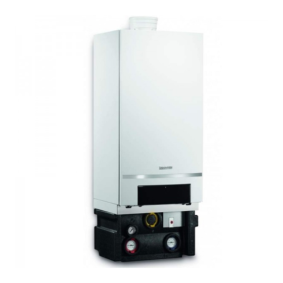
Installation, commissioning and servicing instructions
Wall hung gas fired condensing boiler
Worcester Commercial Boiler Series
GB162-50/65/85/100 V2
For central heating systems and indirect fed domestic hot water
These appliances are for use with Natural Gas or L.P.G.
(Cat. II
type C
2H3P
13
Natural Gas
If you smell gas:
▶ Well away from the building: In Great Britain call the National
Gas Emergency Service on 0800 111 999.
In Northern Ireland call 0800 002 001 and in Ireland call
1850 20 50 50
▶
L.P.G. boilers: Call the supplier's number on the side of the
gas tank.
UK/IE
, C
& C
)
33
53
Model
GC Number
50-V2
41-406-66
65-V2
41-406-67
Table of Contents

Related Manuals for Bosch Worcester GB162-50 V2


Summary of Contents for Bosch Worcester GB162-50 V2
- Page 1 Installation, commissioning and servicing instructions Wall hung gas fired condensing boiler Worcester Commercial Boiler Series GB162-50/65/85/100 V2 For central heating systems and indirect fed domestic hot water These appliances are for use with Natural Gas or L.P.G. (Cat. II type C &...
-
Page 2: Table Of Contents
Table of Contents Table of Contents Electrical connection ........26 Control principle . -
Page 3: Key To Symbols And Safety Precautions
Key to symbols and safety precautions Abbreviations Key to symbols and safety precautions Ø Diameter Natural Gas Key to symbols Liquid Petroleum Gas Warnings Central Heating Warnings in this document are identified by a warning Domestic Hot Water triangle printed against a grey background. Ingress Protection Keywords at the start of a warning indicate the type and Boiler identification module... - Page 4 Key to symbols and safety precautions HEALTH AND SAFETY Irish Standards The appliance contains no asbestos and no substances have been used The relevant Irish standards should be followed, including: in the construction process that contravene the COSHH Regulations • ECTI National rules for electrical installations (Control of Substances Hazardous to Health Regulations 1988).
-
Page 5: Appliance Information
Appliance information Appliance information Determined use The appliance may only be used for the heating of central heating water in a sealed system and for DHW (Domestic Hot Water) heating in closed- loop DHW and heating systems. Any other use is considered inappropriate. -
Page 6: Table Of Contents
Appliance information LPG conversion 2.10 Pump anti-seizure This boiler is approved for the gas type specified on the data plate. If the The pump starts automatically for 10 seconds every 24 hours if the boiler can be converted for another gas type, corresponding information pump has not been operated during this time. -
Page 7: Product Overview
Appliance information 2.12 Product overview 10 11 12 13 14 Wall mounted gas condensing boiler: Control panel Terminal strip Condensate sump Burner cover release clips Auto air vent Air intake pipe Venturi nozzle Data plate Gas valve [10] Combustion air connection (concentric) [11] Flue gas connection (concentric) -
Page 8: Wiring Diagram
Appliance information 2.13 Wiring diagram 24 VAC 0 VAC 24 VAC 10 VAC 10 VAC 230 VAC 230 VAC 24 V RAC 24 VAC 1 2 3 4 13 12 11 10 9 8 7 6 5 4 3 2 1 6720814332-7.1TD Fig. -
Page 9: Specifications
Appliance information 2.14 Specifications 50-V2 65-V2 85-V2 100-V2 General Information Unit Rated output G20 (50/30 °C) [P cond] 14.3 – 49.9 14.3 – 69.5 20.8 – 84.5 20.8 – 99.5 Rated output G20 (80/60 °C) [P 13.0 – 46.5 13.0 – 62.6 18.9 – 80.0 19.0 – 94.5 Rated input G20 [Q (Hi)] 13.3 –... -
Page 10: Gas Specification
Pre-Installation 2.16 Gas specification 2.18 Residual head Gas consumption Maximum gas consumption m³/h 100-V2 Gas type 50-V2 65-V2 85-V2 100-V2 Natural gas E, H, E (G20) 5.03 6.81 8.68 10.24 85-V2 65-V2 Propane 3P (G31) 1.80 2.48 3.19 3.76 50-V2 Table 5 Gas consumption min. -
Page 11: Water Quality
• Radiator valves should conform to BS2767:10. ▶ Do not use any chemical additives (e.g. inhibitors or pH-increasing or reducing agents) other than those approved by Bosch • All other valves should conform to BS1010. Thermotechnology ( table 9). The pH of the heating system water •... -
Page 12: Condensate Pipe Work
Pre-Installation SYSTEM FILL Heating return Non return Non return valve valve Hose return Mains supply Stop Stop cock cock Test cock Temporary hose 6720648726-73.1TD Fig. 9 System fill - category 3 Fig. 12 Sealed system with zone valves Requirements Fluid Category 4 systems: •... -
Page 13: External Connections
Pre-Installation Wherever possible, the condensate drainage pipe should be routed and terminated so that the condensate drains away from the boiler under gravity to a suitable internal foul water discharge point such as an internal soil and vent stack. A suitable permanent connection to the foul waste pipe should be used. - Page 14 Pre-Installation Condensate soak away • The condensate drainage pipe may be run above or below the ground to the soak away. The examples shown on this page run above ground. • The soak away must use a 100mm Ø plastic tube with two rows of three 12mm holes on 25mm centres and 50mm from the bottom of the tube.
-
Page 15: Pressure Relief Pipe Work
Pre-Installation 25mm min. 6720813171-18.1TD Fig. 19 Condensate pump to external disposal Condensate discharge from boiler Condensate pump [13] Insulate and increase pipe size [14] Pipe work transition Condensate trap of 75mm already incorporated into the boiler 6720643895-08.1Wo Pressure relief pipe work Fig. -
Page 16: Boiler Location And Clearances
Pre-Installation Boiler location and clearances Flue options 3.7.1 Installation and servicing clearances CAUTION: in domestic installations ▶ Where a flue system is not going to be accessible, provision must be made for service and inspection. ▶ Voids containing concealed flues must have at least one inspection hatch no less than 300mm square. -
Page 17: Maximum Flue Length (L)
Pre-Installation 415 mm 25 mm 6720648726-28.2TD Fig. 23 Side flue and rear flue installation Standard vertical flue pack ( fig. 24) for 50-V2 and 65-V2: • Concentric vertical flue pipe 80/125; • Wall clamp. Standard vertical flue pack ( fig. 24) for 85-V2 and 100-V2: •... -
Page 18: Standard 100 Mm Flue Systems
Pre-Installation 3.8.6 Flue pipe preparation and assembly Model Reduced flue length [m] ▶ Measure the flue length L. Refer to figures 28 and 29. concentric flue system concentric flue system 100/150 mm 80/125 mm bend extension bend extension 45° 90° 0.5m 45°... -
Page 19: Flue Gas Connection
Pre-Installation An inner flue finishing kit [1] is provided which should be fitted to the ducts before assembly. Roof terminal ▶ Push the assembly through the wall and slide the terminal onto the flue connector. Ensure that the terminal is fully entered into the socket on the boiler. -
Page 20: Flue Terminal Positions
Pre-Installation 3.10 Flue terminal positions All measurements in millimetres 1,500 1,500 300 300 300 300 1,200 Boundary Line Fig. 32 Flue terminal positions - 50-V2 and 65-V2 NOTICE: ▶ All measurements are the minimum clearances required. ▶ Terminals must be positioned so to avoid combustion products entering the building. ▶... -
Page 21: Transport
Transport If the lowest part of the terminal is less than 2 metres above the level of Check gas type the ground, balcony, flat roof or place to which any person has access, ▶ Make sure that the gas type to which the boiler is connected the terminal must be protected by a guard. -
Page 22: Remove The Protective Caps
Fitting Mounting on a cascade frame Flat gasket 1½ " (2 × ) Gas isolation valve ▶ For details on mounting the boiler in a cascade frame, see the PRV and condensate T-piece installation instructions for the cascade system. Connection piece Remove the protective caps Flow pipe 5.6.1... -
Page 23: Hydraulic And Gas Connections (Without Pump Group)
Fitting ▶ Connect the flow and return line to the pump group, making sure they ▶ Connect the gas pipe without stress to the gas isolation valve. are free of stress. The minimum diameter of the supply and return line must be 1½ " (Ø 35 mm). 6 720 807 034-005.1DDC Fig. -
Page 24: Install The Low Loss Header
Fitting Install the low loss header ▶ Install the condensate trap. If the residual head is insufficient with the required flow rate ( tab. 8, page 10), a low loss header [1] must be installed to hydraulically separate the boiler and secondary circuit pumps. 6720812338-2.1TD Fig. -
Page 25: Connecting The Condensate Drain
Fitting With pump group ▶ Remove the cap from the connection point [1]. ▶ Install the tee [1] between the pressure relief valve and the siphon. ▶ Connect the connection pipe of the expansion vessel to the Combined PRV and condensate is optional. connection point. -
Page 26: Electrical Connection
Electrical connection Electrical connection CAUTION: Risk of electric shock ▶ Always isolate the boiler from the power supply before working on the electrical parts. Guard against unintentional re-connection. NOTICE: Short circuit. ▶ Only use original cables if they must be replaced. 6 720 807 034-069.1TD Fig. -
Page 27: Installation Of The Strain Relief
Electrical connection ▶ Connect the components to the relevant plug. ▶ Tighten the screw of the strain relief. 6720807034-49.1TD Fig. 51 Terminal strips 24 V AC terminal strip 230 V AC terminal strip Installation of the strain relief ▶ Always pass the cable to be installed through a supplied strain relief mechanism before attaching it to a mains plug. -
Page 28: Connecting The Modulating Controller
Electrical connection ▶ Install the RTH convertor as specified in the accompanying wiring ▶ Connect the outside temperature sensor, supplied with weather instructions. compensating controller, via the blue connector block on the terminal strip [1]. Connecting the modulating controller The following modulating controllers can be connected: •... -
Page 29: Connecting To The Mains
Operating the boiler ▶ Connect the pump's power cable to the green connector block on the terminal strip [2]. 6 720 807 034-020.1TD Fig. 59 Connection of pump 6.14 Connecting to the mains 6720648726-59.2TD DANGER: Danger of fatal accident due to electric shock. Fig. -
Page 30: Information Menu
Operating the boiler Info Information menu The boiler status is displayed via the key. No information about DHW mode is shown here. Display Display values, settings and codes can be read off the display. When the boiler is first switched on via the mains plug, all symbols appear briefly Display of service code. -
Page 31: Chimney Sweep Mode
Operating the boiler ▶ Hold down to switch off the chimney sweep mode. Setup menu Heating mode is switched on. Setting: On, Off. ▶ Set the maximum boiler flow temperature based on the heating system type. Adjustment range: 30 - 90 °C. Examples of settings: •... -
Page 32: Commissioning
Commissioning Adjusting the output Commissioning The output of the boiler can be adapted to the heat energy demand via the setup menu. Proceed as follows: WARNING: Gas explosion. ▶ Adjusting the output via the setup menu ( Chapter 7.2). ▶ Check for gas tightness after carrying out work on Observe the following table when making the adjustment. -
Page 33: Measure Gas/Air Ratio
Commissioning ▶ Undo the test nipple for the gas supply pressure [1] by turning it through 2 revolutions. 6 720 807 034-025.1DDC Fig. 68 Connecting the pressure gauge at the 85-V2 and 100-V2 ▶ Open the gas isolation valve. ▶ Bring the boiler into operation. 6 720 807 034-61.1DDC ▶... - Page 34 Commissioning ▶ Remove the cap of the flue gas testing point [1]. 6 720 807 034-066.1DDC Fig. 70 Open the burner pressure nipple at the 85-V2 and 100-V2 ▶ Connect the pressure gauge. ▶ Set the pressure gauge to “0”. Hold the pressure gauge at the same height when the measurement is in progress.
-
Page 35: Co And Combustion Checks
▶ The gas valve is factory set and must not be adjusted during commissioning if found to be out of tolerance, please contact the Worcester, Bosch Group help line 0330 123 3366. Zero the analyser Set boiler to ≥... -
Page 36: Measure Ionisation Current
Commissioning 8.10 Measure ionisation current ▶ Check the rubber gasket [1] at the ignition unit and the monitoring electrode for tightness. ▶ Take the boiler out of operation. ▶ Pull the connector plugs apart. ▶ Connect the multi-meter on both sides of the open plugs (in series). 6 720 807 034-65.1DDC Fig. -
Page 37: Commissioning Report (For Installations Below 70Kw)
Shutdown 8.15 Commissioning report (for installations below Environmental protection 70 kW) ▶ Sign all completed commissioning work and enter the date. Environmental protection is one of the principal policies for Worcester. We regard quality of performance, economy and environmental Measured protection as equal objectives. -
Page 38: Remove The Gas-Air Unit
Inspection and servicing 11.2 Remove the gas-air unit ▶ Release the 4 snap fasteners on the burner cover. The snap fasteners are under tension. ▶ Remove the mains plug and control signal to the fan. 6 720 807 034-042.2DDC Fig. 76 Removing the mains plug of the fan ▶... -
Page 39: Cleaning The Heat Exchanger
Inspection and servicing ▶ Take off the burner. 11.5 Checking the ignition system NOTICE: Damage to the glow ignitor. The glow ignitor unit is made of breakable material. ▶ Handle with care. NOTICE: Damage to the boiler. Since the effectiveness of the gaskets in the ignition device is reduced, the boiler may be damaged. -
Page 40: Clean Condensate Trap/Siphon
Inspection and servicing ▶ Align gasket [2] carefully on the burner. 11.7 Cleaning the condensate sump If the siphon is soiled, check and clean the condensate sump as necessary. ▶ Pull the condensate hose down and turn it towards the rear. 6 720 807 034-041.1DDC Fig. -
Page 41: Testing The Gas Supply Pressure
Inspection and servicing ▶ Remove condensate sump. 6 720 807 034-066.1DDC Fig. 92 Opening the burner pressure test nipple (85-V2 and 100-V2) ▶ Connect pressure gauge. 6 720 807 034-46.1DDC ▶ Set pressure gauge to “0”. Fig. 90 Removing the condensate sump Hold the pressure gauge at the same height when the measurement is in progress. -
Page 42: Check Flue Gas Non-Return Valve
Inspection and servicing 11.12 Measure ionisation current See chapter 8.10“Measure ionisation current”. -5 Pa -10 Pa 0 Pa 11.13 Testing for gas leaks See chapter 8.11“Testing for gas leaks”. 11.14 Check for correct operating characteristics ▶ Check all fittings for leaks. ▶... -
Page 43: 11.15 Inspection And Maintenance Reports
Inspection and servicing 11.15 Inspection and maintenance reports Date: Date: Date: Date: Date: Date: Inspection work ____________ ____________ ____________ ____________ ____________ ____________ Check the general condition of the heating system. Carry out a visual inspection and function check of the heating system. -
Page 44: Display Codes
Display codes Display codes 12.2 Reset Display codes give an indication of the operating condition of the boiler. Fault codes are either shown in the display directly or can be called up For safety reasons, the boiler shuts down and locks as soon as a serious via the information menu. - Page 45 Display codes Code Code type Designation Remedy 3 6 1 The burner control unit that has been fitted is not ▶ Check the numbers on the burner control unit. compatible with the KIM. ▶ Fit a KIM with the correct KIM number. 2 3 3 The burner control unit or the KIM is faulty.
- Page 46 Display codes Code Code type Designation Remedy 2 8 6 The boiler return temperature sensor has ▶ Check the water pressure of the boiler, vent the heating system and detected a return temperature higher than the boiler. 105 °C. ▶ Check whether it is possible to achieve sufficient flow in the heating system.
- Page 47 Display codes Code Code type Designation Remedy 2 2 7 2 + 3 An insufficient ionisation current was measured ▶ Check the boiler for soiling. following ignition of the burner. ▶ Check the gas supply pressure. ▶ Check the gas/air ratio. ▶...
- Page 48 Display codes Code Code type Designation Remedy 2 7 8 The sensor test has failed. ▶ Check the cabling and plug of the sensors. ▶ Check the operating characteristics of the sensors. Replace the faulty component if necessary. 2 7 9 The burner control unit or the KIM is faulty.
- Page 49 Notes 6720814332 (2018/04)
- Page 50 GAS BOILER SYSTEM COMMISSIONING CHECKLIST This Commissioning Checklist is to be completed in full by the competent person who commissioned the boiler as a means of demonstrating compliance with the appropriate Building Regulations and then handed to the customer to keep for future reference. CONTROLS Optimum start control Fitted...
- Page 51 SERVICE RECORD It is recommended that your heating system is serviced regularly and that the appropriate Service Interval Record is completed. Service Provider SERVICE 01 SERVICE 02 ² % ² % ² % ² % SERVICE 03 SERVICE 04 ² % ²...
- Page 52 0330 123 9779 LITERATURE: 0330 123 9119 TRAINING: 0330 123 0166 SALES: 0330 123 9669 Worcester, Bosch Group Cotswold Way, Warndon, Worcester WR4 9SW. Tel. 0330 123 9559 Worcester, Bosch Group is a brand name of Bosch Thermotechnology Ltd. worcester-bosch.co.uk 6720814332...