Table of Contents
APPLICATION
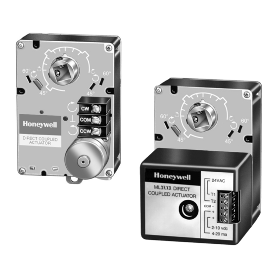
The 35 and 70 lb-in. Non-Spring Return Direct Coupled
Actuators (DCA) are control actuators that provide floating or
proportioning control for valves and dampers. The
proportioning actuators accept a current or voltage signal from
a controller to position the damper or valve at any chosen
point between fully open and fully closed. Floating actuators
are suitable for use with single pole double throw (spdt)
floating thermostats or two-position control systems.
Two-position control requires installation of the 201052B
Auxiliary Switch.
® U.S. Registered Trademark
Copyright © 2003 Honeywell International Inc.
All Rights Reserved
Non-Spring Return
Direct Coupled Actuators
ML6161, ML7161, ML6174, ML7174
FEATURES
• Selectable 45°, 60°, or 90° stroke in both clockwise
(cw) or counterclockwise (ccw) directions.
• 0° to 30° minimum position adjustment (cw or ccw
direction) on all models.
• Magnetic coupling eliminates the need for mechanical
stops.
• Two field-addable auxiliary switches.
• Auxiliary feedback potentiometer field-addable on
select models.
• Manual declutch on all models.
• ML7161 and ML7174 models include standard reverse/
direct acting rotation switch on outside cover.
• W7620 Terminal Unit Controller compatibility.
• Commercial zone damper in W7600 Commercial Zone
System compatibility.
Application ........................................................................
Features ...........................................................................
Specifications ...................................................................
Ordering Information ........................................................
Installation ........................................................................
Operation .......................................................................... 10
Checkout .......................................................................... 12
35 and 70 lb-in.
PRODUCT DATA
Þ
Contents
1
1
2
2
5
63-2209-8
Table of Contents

Related Manuals for Honeywell ML6161 Series


Summary of Contents for Honeywell ML6161 Series
- Page 1 Two-position control requires installation of the 201052B Auxiliary Switch. Contents Application ................ Features ................Specifications ..............Ordering Information ............Installation ................ Operation ................10 Checkout ................12 ® U.S. Registered Trademark Þ Copyright © 2003 Honeywell International Inc. All Rights Reserved 63-2209-8...
- Page 2 If you have additional questions, need further information, or would like to comment on our products or services, please write or phone: 1. Your local Honeywell Automation and Control Products Sales Office (check white pages of your phone directory). 2. Honeywell Customer Care...
- Page 3 35 AND 70 LB-IN. NON-SPRING RETURN DIRECT COUPLED ACTUATORS Table 4. Actuator 90° Stroke Timing. Table 1. 35 lb-in. and 75 lb-in. DCA models. At 50 Hz At 60 Hz ML Motor Linkage 90 Second Models 108 sec 90 sec 61 Floating Control Three-Minute Models 216 sec...
- Page 4 35 AND 70 LB-IN. NON-SPRING RETURN DIRECT COUPLED ACTUATORS 1-13/16 (46) 3-5/8 (92) (25) 3 IN. (76 MM) 1-13/16 MINIMUM SPACING (46) REQUIRED FOR REMOVING CONDUIT COVER 5-7/8 (149) (22) 3-3/4 (95) M18018 Fig. 1B. Approximate dimensions of ML6161C,D and ML6174C,D DCA in in. (mm). 63-2209—8...
- Page 5 35 AND 70 LB-IN. NON-SPRING RETURN DIRECT COUPLED ACTUATORS INSTALLATION When Installing this Product... These actuators are shipped in the fully clockwise 90° position as viewed from the end of the damper shaft. 1. Read these instructions carefully. Failure to follow them could damage the product or cause a hazardous condition.
- Page 6 35 AND 70 LB-IN. NON-SPRING RETURN DIRECT COUPLED ACTUATORS Installation TYPE A DAMPER After determining the direction of the shaft rotation (cw or ccw), install the device. For valve linkage mounting, refer to the instructions shipped with the linkage. For damper mounting, proceed as follows: FLOW 1.
- Page 7 35 AND 70 LB-IN. NON-SPRING RETURN DIRECT COUPLED ACTUATORS 1. Determine the direction of the desired closing rotation. 2. Move the actuator to the position fully opposite the RANGE STOP PIN desired closing rotation (if cw closing rotation is desired, move the actuator to the full ccw position).
- Page 8 35 AND 70 LB-IN. NON-SPRING RETURN DIRECT COUPLED ACTUATORS IMPORTANT Run an entire check of the operation after completing COVER this procedure. THIS SETSCREW CORRESPONDS WITH CLOSING IN THE THIS SETSCREW CW DIRECTION CORRESPONDS WITH CLOSING IN THE CCW DIRECTION CONDUIT KNOCKOUTS M10075...
- Page 9 35 AND 70 LB-IN. NON-SPRING RETURN DIRECT COUPLED ACTUATORS IMPORTANT Failure to follow the calibration procedures can result ML7161, ML7174 in improper resistance values at desired stroke. (HOT) AUXILIARY POTENTIOMETER – – MOTOR POSITION RESISTANCE RESISTANCE + mA FULLY CW 500 OR 0 OHMS 24V (COM-CW)
- Page 10 35 AND 70 LB-IN. NON-SPRING RETURN DIRECT COUPLED ACTUATORS OPERATION T641A THERMOSTAT VAV Systems VAV systems control the temperature within a space by varying the volume of supply air temperature. The system delivers air to the space at a fixed temperature. The space thermostat controls the volume of supply air by modulating the supply air damper.
- Page 11 35 AND 70 LB-IN. NON-SPRING RETURN DIRECT COUPLED ACTUATORS Rotation Reversal Switch (ML7161, ML7174) Use the rotation reversal slide switch to reverse the actuator T641A THERMOSTAT rotation. The switch is located on the bottom of the actuator housing (see Fig. 5). To change rotation to counterclockwise (ccw) , change the slide switch.
- Page 12 10.00 ±0.7 Vdc Actuator remains at cw position. 8.50 ±0.6 Vdc Actuator leaves cw position. Automation and Control Solutions Honeywell International Honeywell Europe S.A. Honeywell Latin American Region Honeywell International Inc. Honeywell Limited-Honeywell Limitée Control Products 3 Avenue du Bourget...