
Related Manuals for Omron Colin VP-1000 plus


Summary of Contents for Omron Colin VP-1000 plus
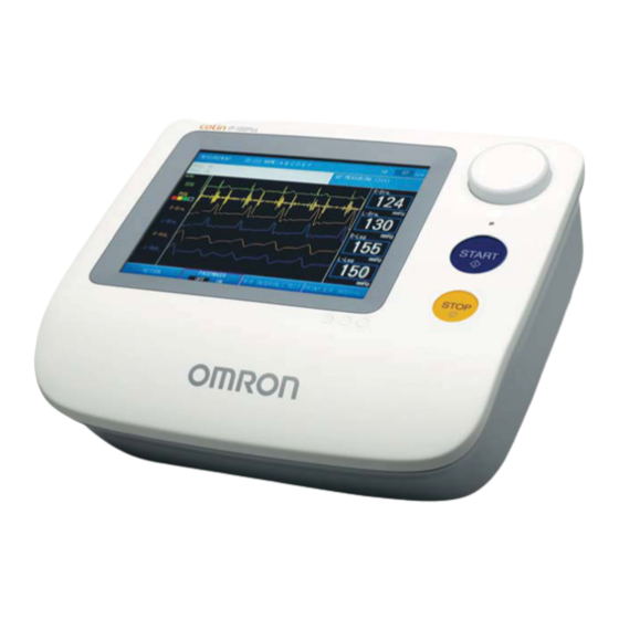
- Page 1 Non-invasive Vascular Screening Device BP-203RPE Thank you for purchasing the OMRON BP-203RPE unit. Read all of the instructions in the manual before you operate the unit and keep the manual near the unit at all times for future reference.
-
Page 3: Table Of Contents
Contents 1. Before Use 1-1. Exemptions ....................3 1-2. Intended Use....................4 1-3. Meaning of Symbols ................... 5 1-4. Safety Information..................6 Explanation of Symbols ................6 1-5. Product and Accessories ................. 13 Main Unit ....................13 Standard Accessories................13 Accessories (Sold Separately) .............. - Page 4 3-4. Facility name / Doctor / Technician / Category Settings......86 Selecting the List Entry Method............. 86 List Entry Procedure ................87 Pre-selection Setting Procedure............91 3-5. Date & Time Settings................. 93 3-6. Printing Reports and Editing Patient Information ........94 Reprinting Measurement Data...............
-
Page 5: Before Use
1. Before Use 1-1. Exemptions Disclaimer Our company assumes no responsibility for the following: 1.Failures, damage, or injuries due to maintenance or repair work performed by other than our company or a company that we specify. 2.Failures or damage to one of our products caused by a product of another manufacturer not delivered by us. -
Page 6: Intended Use
Durable Period 5 years, provided that the appropriate maintenance has been done from production date. (Self-certification through OMRON HEALTHCARE's own data) Measurement Parameter ■ Non-invasive Blood Pressure ■ Heart Rate ■ Pulse Wave ■... -
Page 7: Meaning Of Symbols
1-3. Meaning of Symbols Start (of action) This way up Stop (of action) Keep away from rain Caution Stacking limit by number (Refer to safety information) Consult instructions for use Temperature limitation Authorised representative in the Catalogue number European community Manufacturer Disposal instructions Date of manufacture... -
Page 8: Safety Information
1-4. Safety Information The warning signs and symbol examples indicated below are intended to ensure safe use of the product and prevent damage and injury to you and others. The signs and symbols are explained below. Explanation of Symbols Indicates a situation where incorrect handling may cause human death or serious injury. Warning Indicates a situation where incorrect handling may cause human injury or physical Caution... - Page 9 1-4. Safety Information Warning: Safety rules when using the product Do not use a frayed or damaged power cord or plug. Otherwise electric shock, short circuiting, or fire may result. Do not touch the power plug with wet hands. Otherwise electric shock or injury may result. Be sure to plug the three-prong power plug into a grounded (three-prong) outlet for medical use (when a printer is included).
- Page 10 1-4. Safety Information Do not attach the arm cuff for patient during medical treatment with intravenous drip or blood transfusion. This may result incorrect diagnosis and treatment. Do not use this device on a patient that cannot express pain. If cuff pressurization does not stop in a specified time, internal hemorrhaging may occur in the upper arm or ankle.
- Page 11 1-4. Safety Information Caution: Safety rules when using the product Observe the rules below when handling the power cord. Failure to observe these rules may result in electric shock or device failure. •Do not damage the cord •Do not break the cord •Do not modify the cord •Do not bend or pull on the cord with undue force •Do not twist the cord...
- Page 12 1-4. Safety Information If a power failure occurs during measurement, immediately remove the cuff. If the patient's ankle or upper arm is pressurized for a long time, internal hemorrhaging may result. Do not attach the cuff on the measurement site below: •Arm with intravenous drip •Upper limb in which a shunt is placed in for hemodialysis Incorrect diagnosis and treatment or an accident may result.
- Page 13 1-4. Safety Information On a bedridden patient, check for lower-limb deep venous thrombus before taking a measurement. Otherwise an accident may result. The ECG clip electrode and PCG sensor pad are disposable supplies. Do not reuse them once they are removed. In case that they are used on moist, injured or infected skin, dispose them right away. Otherwise an infection may result.
- Page 14 • Do not use an autoclave, ultraviolet radiation, or gas disinfection (EOG, formaldehyde gas, concentrated ozone, etc.) to disinfect the device • If a fuse blows, there may be a problem in the device. Contact a dealer or an Omron Healthcare technical support representative •...
-
Page 15: Product And Accessories
1-5. Product and Accessories Before using this product, make sure that no accessories are missing and that neither the unit nor the accessories are damaged. Contact a dealer or an Omron Healthcare technical support representative If any accessory is missing or damaged. - Page 16 1-5. Product and Accessories BP-203RPE3 arm cuffs, left and right pair PCG weight (M size: For arm girths from 20 to 32 cm) BP-203RPE3 arm cuff hoses, left and right Sensor gel packet (consumable packet) 5 pair sets • PCG sensor pad, 1 piece x 5 •...
-
Page 17: Accessories (Sold Separately)
1-5. Product and Accessories Accessories (Sold Separately) Product description Model Right arm cuff, S size 9999492-9 HEM-CS30-RIGHT Right arm cuff, M size 9999490-2 HEM-CR30-RIGHT Right arm cuff, L size 9999496-1 HEM-CL30-RIGHT Left arm cuff, S size 9999494-5 HEM-CS30-LEFT Left arm cuff, M size 9999491-0 HEM-CR30-LEFT Left arm cuff, L size... -
Page 18: Options
OMRON HEALTHCARE Co., Ltd. OMRON HEALTHCARE Co., Ltd. permits the customer to install and use this product package on the BP-203RPE 3 unit indicated in this license certificate. -
Page 19: Name And Function Of Each Part
1-6. Name and Function of Each Part Main Unit Enter patient information, configure settings, and perform measurement. Back 1. LCD display (touch panel) 5. [STOP] button When configuring settings: Setting buttons appear. Press to interrupt and stop measurement. Touch the setting buttons with the touch pen to enter On the screen with the [BACK] button, the [STOP] settings. -
Page 20: Stand
1-6. Name and Function of Each Part Stand 1. Arm 8. Cable hook The sensors are placed on this arm. Hang the sensor box cable on this hook. 2. PCG sensor pocket 9. Tray Stores the PCG sensor. Stores supplies on the tray. 3. -
Page 21: Installation/Moving
1-7. Installation/Moving Do not install or store the device in a location where water or chemicals may splash on Warning the device. Electric shock may result. Do not install in a location where the temperature or humidity is outside the allowed Caution range. -
Page 22: Procedure For Moving
1-7. Installation/Moving Procedure for Moving When you need to move the device, follow the procedure below. Turn the power switch to the off ( ) position. Remove the power plug from the outlet and coil the cord. Please do not pull the power cord. Store the sensors on the arm. - Page 23 1-7. Installation/Moving Unlock the casters. Grasp the handle and move the device. Do not push or pull any other parts rather than the handle. After moving the device, lock the casters to secure the stand.
-
Page 24: Measurement Procedure
2. Measurement Procedure 2-1. Preparing for Measurement Measurement Procedure Turn the power on Have the patient in a supine position on the bed and remain quite Enter or check patient information Attach the cuffs and sensors to the patient Make sure that "ECG: OK" and "PCG: OK"... -
Page 25: Patient Information
2-1. Preparing for Measurement Patient Information Patient information is required to properly maintain a measurement history. Input items marked "Required" must be entered. Item name Input Page Required Birth Date Height Name Weight Waist Disease Order Number* Measurement Sensors Measurement Optional Sites Upper limit of... -
Page 26: Initial Screen (Id Entry Screen)
2-1. Preparing for Measurement Initial Screen (ID Entry Screen) Following a brief interval after the power is turned on, the ID entry screen appears. This screen is called the "initial screen" in this manual. The ID is entered in this screen. You can select whether the ID input type is all numbers, or both numbers and alphabetical characters. -
Page 27: Entering And Editing Patient Information
2-1. Preparing for Measurement Entering and Editing Patient Information Enter the patient information and edit previously stored patient information. Notes: • Do not assign multiple IDs to a single patient. Even if all other information such as the name is the same, the system will treat different IDs as different patients. In this case, you will not be able to make full use of the device's functions for long-term storage of measurement histories and diagnosis support. - Page 28 2-1. Preparing for Measurement Entering the ID Number Follow the steps below to enter an ID number for the first time or check existing ID numbers. Up to 13 characters (including hyphens "-") can be entered. ID number must be entered. For entering an Order number, up to 16 digits of number (including hyphens"-") can be entered.
- Page 29 2-1. Preparing for Measurement Register patient information screen For the items to be entered, see pages 28 to 39. 1 Enter patient information 2 Press the [NEXT] button [BACK] button: Return to the initial screen. [HMC DATA PROC] button: Can be used when the optional HMC Package is connected. [NEXT] button: Proceed to the measurement screen.
- Page 30 2-1. Preparing for Measurement Entering the Name Press the [NAME] button. Enter the name. • Up to 40 characters can be entered. • A space counts as one character. • To enter a space, press the [SPACE] button. • To switch between upper case and lower case letters, use the [UPPER] button / [lower] button.
- Page 31 2-1. Preparing for Measurement Entering the Sex This must be entered. If not entered, measurement cannot be performed. Press the [SEX] button. Press the [SEX] button to select the sex. The selection switches between "Male" and "Female" each time you press the [SEX] button.
- Page 32 2-1. Preparing for Measurement Entering the Date of Birth This must be entered. If not entered, measurement cannot be performed. A date of birth less than one year prior to the day the information is being entered cannot be entered. The device cannot be used for an infant less than one year old. Press the [BIRTH DATE] button.
-
Page 33: Weight
2-1. Preparing for Measurement Entering the Height This must be entered. If not entered, measurement cannot be performed. The height is required for calculation of the PWV (Pulse Wave Velocity). Press the [HEIGHT] button. Enter the height and press the [OK] button. •... -
Page 34: Disease
2-1. Preparing for Measurement Entering the Waist Press the [WAIST] button. Enter the waist and press the [OK] button. • The input range is 30 cm to 250 cm. • To cancel entry, press the [CANCEL] button. Selecting the Disease Press the [DISEASE] button. -
Page 35: Order Number
2-1. Preparing for Measurement Entering the Order Number The order number used for the electronic chart can be entered. Note: Once a patient information screen has been opened by entering the ID number or order number in the initial screen, entering and changing is not possible. Press the [ORDER NO.] button. -
Page 36: Measurement Sensors
2-1. Preparing for Measurement Setting the Measurement Sensors Press the [MEAS. SENSOR] button. Set the measurement sensors. • Specify settings for the ECG, PCG. Sensor attached: [ON] Sensor not attached: [OFF] Press the [OK] button. To cancel entry, press the [CANCEL] button. Note: Even when ECG is "OFF", if the HR Synchronized tone setting is "ON"... - Page 37 2-1. Preparing for Measurement Setting the Measurement Sites The cuffs are normally attached to both brachia and both ankles. If a shunt is placed on an arm for hemodialysis, do not attach a cuff to or perform measurement on that arm. Press the [MEAS.
-
Page 38: Upper Limit Of Pressurizing
2-1. Preparing for Measurement Setting the Upper Limit of Pressurizing Specify the upper limit of pressurizing settings for the right ankle and left ankle. Normally "Auto" is selected. When "Auto" is set, the system pressurizes the cuff and measures the patient's blood pressure automatically. - Page 39 2-1. Preparing for Measurement Press the [OK] button. To cancel entry, press the [CANCEL] button. Notes: • The optimum value for the pressurizing limit is generally "maximum blood pressure + 60 mmHg". • If the pressurizing upper limit setting is not suitable, the measured values of the blood pressure may be low as shown below.
- Page 40 2-1. Preparing for Measurement Synchro Measurement Setting In synchro measurement, blood pressure is measured twice. In the second measurement, the measurement timing is automatically adjusted based on the blood pressure value of the first measurement and all four limbs are measured simultaneously. Press the [SYNC MEAS.] button.
- Page 41 2-1. Preparing for Measurement Selecting the Technician Select the technician from the list. The list must be stored in advance. Refer to "3-4. Facility name / Doctor / Technician / Category Settings" (page 86). Press the [TECHNICIAN] button. Select the technician and press the [OK] button. •...
-
Page 42: Displaying The Measurement History
2-1. Preparing for Measurement Displaying the Measurement History A history of the patient's past measurement data can be displayed. The measurement history can only be viewed from the confirm patient Information screen. Press the [MEAS. HISTORY] button. View the measurement history in the measurement history screen. -
Page 43: Attaching The Cuff And Sensor
2-1. Preparing for Measurement Attaching the Cuff and Sensor •Ensure there is no kink or closing of cuff and/or hose. When there is kink or closing in the cuff and/or hose, air is not let out from the cuff. This may result in bad blood circulation in the arm, causing peripheral functional disorder. - Page 44 2-1. Preparing for Measurement Have the patient in a supine position. Expose the patient's upper arm so that it is bare or has only one layer of thin clothing. If the cuff is being placed over thin clothing, pull the clothing straight so that it does not bunch up at the artery.
- Page 45 2-1. Preparing for Measurement Attaching an Ankle Cuff Notes: • If you are measuring on a single ankle, make sure the cuff setting for the other ankle is "OFF" when you enter patient information. (Refer to page 35). • Keep the foot with the cuff attached at the level of the heart. •...
- Page 46 2-1. Preparing for Measurement Attaching the ECG clips •The ECG clip electrodes are disposable supplies. Do not reuse them once they are removed. In case that they are used on moist, injured or infected skin, dispose them right away. Otherwise an infection may result. •Do not use a worn or expired ECG clip electrode.
- Page 47 2-1. Preparing for Measurement Attach the ECG clip for the left wrist. • Attach the clip so that the electrode is on the inner side of the wrist. • Make sure that both electrodes are in full contact with the wrist. Attaching the PCG sensor •The PCG sensor pad is disposable supply.
- Page 48 2-1. Preparing for Measurement Attach the PCG sensor. • Normally the PCG sensor is placed at the left edge of the sternum in the fourth intercostal space (4). If the second heart sound is not clear, measurement can also be performed with the sensor in the middle of the third intercostal space (5), or near the right edge of the sternum in the second intercostal space (6).
-
Page 49: Basic Measurement
2-2. Basic Measurement Viewing the Measurement Screen After the patient information has been entered and the cuffs and sensors have been attached to the patient, measurement can be started. Press the [NEXT] button in the new patient information registration screen or the patient information review screen to proceed to the measurement screen. -
Page 50: Contents Of The Measurement Screen
2-2. Basic Measurement Contents of the Measurement Screen ECG Message Displays the ECG status (refer to page 49). PCG Message Displays the PCG status (refer to page 50). Shows the detected PCG level using a four-level meter. For optimum measurement, the meter should be lit to at least the third level before measurement starts. - Page 51 2-2. Basic Measurement ECG Messages Note: If "ECG" was set to "OFF" in the "SELECT MEASUREMENT SENSOR" settings when the patient's information was entered (refer to page 34), ECG messages and the ECG wave will not appear. ECG messages are explained below. When "OK" is not displayed, measurement accuracy may be reduced.
- Page 52 2-2. Basic Measurement PCG Messages Note: If "PCG" was set to "OFF" in the "SELECT MEASUREMENT SENSOR" settings when the patient's information was entered (refer to page 34), PCG messages and the PCG level indicator will not appear. The PCG messages are explained below. When "OK" is not displayed, measurement accuracy may be reduced.
-
Page 53: Starting And Ending Measurement
2-2. Basic Measurement Starting and Ending Measurement Note: In some cases one measurement is required and in some cases two measurements are required to complete measurement. Two measurements are required in the following cases: • "Synchro measurement" setting is set to "ON" (refer to page 38). •... -
Page 54: Measurement
2-2. Basic Measurement Make sure that measurement has ended. • When measurement ends, the measurement results screen appears. " " Refer to Contents of the Measurement Screen (page 48). • If the number of printed pages is set in "Print Default Settings"... -
Page 55: Measurement Results
2-3. Measurement Results Contents of the Measurement Results Screen The measurement results screen that appears when measurement ends is explained below. Blood pressure Displays the blood pressure values at each site where measurement was value performed. Sites where measurement was not performed are not displayed. Graph This graph shows the relationship between baPWV and ABI. -
Page 56: Measurement Results Reports
2-3. Measurement Results Measurement Results Reports The measurement results reports that are printed when measurement ends are explained below. The types of reports are as follows. Type Description Page Measurement results report that is retained by the medical Standard organization that conducted the examination. Patient Measurement results report to be given to the patient. - Page 57 2-3. Measurement Results Standard Report go to next page...
- Page 58 2-3. Measurement Results Patient information The patient information that was entered before measurement. Shows the measured heart rate. If "ECG" was set to "OFF" in the "SELECT Heart Rate/ MEASUREMENT SENSOR" settings when the patient's information was Pulse Rate entered, shows the pulse rate. (refer to page 34) The ECG waveform.
- Page 59 2-3. Measurement Results When "Show result" is selected in "Over all grade" in "Print Default Settings", an Over all grade over all grade of the examination results is shown using three levels (A, B, C) (refer to page 84). When "Vascular age" or "Vascular age (N)" is selected in "Stiffness" in the "Print Vascular age Default Settings", this shows arterial stiffness as a vascular age (refer to page 84).
- Page 60 2-3. Measurement Results Graph 1 (Graph 2) ■ The graphs that appear in Graph 1 and Graph 2 are set in "Standard report layout" in "Print Default Settings" in advance (page 83). Type Description Displayed graph This shows baPWV vs. age on the 1.
- Page 61 2-3. Measurement Results Type Description Displayed graph This shows baPWV vs. maximum blood 7. SYS-baPWV pressure value on the horizontal axis. This shows baPWV vs. minimum blood 8. DIA-baPWV pressure value on the horizontal axis. This shows baPWV vs. date on the 9.
- Page 62 2-3. Measurement Results Patient Report This is the measurement results report that is given to the patient. Select from three types depending on the patient and the diagnosis policy. The report layout can be selected for No. 1 and No. 2. The report type is set in advance in "Report type" in "Print Default Settings" (page 81) and the layout is set in "Patient Report Layout"...
- Page 63 2-3. Measurement Results This is printed when "Show frame" or "Show result" is selected in the "Over all grade" setting in "Patient report layout". An over all grade of the test results is given in "Show result" (refer to page 84). Over all grade A: Not particular B: Follow-up is required...
- Page 64 2-3. Measurement Results Patient Report No. 2 ■ This mainly consists of graph display of clogging and flexibility of arteries. Select from three types of layouts based on the "Stiffness (Vascular sclerosis indication)" selection (page 84). Notes: • The horizontal axis representing time on the artery flexibility trend graph is automatically set within a range of 1 to 5 years depending on the patient's past data.
- Page 65 2-3. Measurement Results Patient Report No. 3 ■ This indicates the risk of cardiovascular disease using illustrations that are easy for the patient to understand. This is evaluated based on an age standard. The "Compare with age" layout or Arterial stiffness "Vascular age"...
- Page 66 2-3. Measurement Results Trend Report This chart indicates measurement data trends based on comparison with past data. This is normally only printed if there is a patient history; however, it can be set to print regardless of whether or not there is a patient history. Refer to "Print Default Settings"...
-
Page 67: R-R Interval Examination
2-4. R-R Interval Examination Use this to measure fluctuations in the interval between heartbeats in order to check the functioning of the automatic nerve system for the cardiovascular system. The one hundred heartbeats that are required for analysis are acquired and the resulting histogram and trend are printed. -
Page 68: R-R Interval Examination Results
2-4. R-R Interval Examination R-R Interval Examination Results The results of R-R interval examination are described below. R-R Interval Examination Report R-R interval This shows the standard deviation of the R-R interval. standard deviation R-R interval mean This shows the mean value of the R-R interval. value HR mean value This shows the mean value of the heart rate. -
Page 69: Stress Mode
2-5. Stress Mode This mode is used to measure blood pressure immediately after the heart is subjected to a set exercise load on a treadmill or similar device. After exercise is finished, the ECG and blood pressure gradually return to the rest state. By measuring this process (recovery), abnormalities can be discovered that would not be apparent when the patient is at rest. - Page 70 2-5. Stress Mode Select the measurement sites and press the [OK] button. Press the [OK] button. Press the [OK] button. Set the exercise stress conditions. • DISTANCE: 0 to 1000 m (Walking distance) • DEGREE: 0 to 30% (Angle of treadmill) •...
- Page 71 2-5. Stress Mode Make sure that "ECG: OK" and "PCG: OK" are displayed. Press the [START] button on the device. Measurement begins. • During measurement the waveform appears. To view numerical values during measurement, press the [SWITCH VIEW] button and select the desired screen from the three screen types.
- Page 72 2-5. Stress Mode • To cancel measurement, press the [MEASUREMENT END] button. When the ABI returns to the state before exercise stress, end the stress test. Press [END STRESS TEST] and then [OK] to end. To cancel, press the [CANCEL] button. Measurement ends, the stress test report will be printed.
-
Page 73: Checking Numerical Values During Stress Test
2-5. Stress Mode Checking Numerical Values During Stress Test The [SWITCH VIEW] button can be pressed in the waveform display screen during or after stress test to switch the screen to "Previous measurement result", "List of results", "ABI - Elapsed time", or "Waveform screen". - Page 74 2-5. Stress Mode List of results screen Shows measured values over time. Shows the maximum blood pressure value. Shows the ABI value. This shows the recovery ratio, which is the ratio of measured ABI to ABI at rest. This approaches 1 as time elapses. ABI - Elapsed time This shows the trend of the ABI value over time.
-
Page 75: Stress Test Results
2-5. Stress Mode Stress Test Results When stress test ends, the stress test report is printed. Patient information The patient information that was entered before measurement. Trend chart This shows the trend of the ABI value over time. Shows a list of the measurement results together with the elapsed time. 4 : "R"... -
Page 76: Settings And Data Processing
3. Settings and Data Processing 3-1. Main Menu Screen To display the main menu screen, press [MAIN MENU] in the initial screen that appears after the power is turned ON. The main menu screen is used to configure basic settings related to the device and settings for printing measurement results, and to process past measurement data. - Page 77 3-1. Main Menu Screen Type Name Description Page The information of previously examined PRINT REPORT / patients can be edited, deleted, and EDIT PATIENT INFO reprinted. You can search for the information of a TREND REPORT previously examined patient using the patient PRINTING ID or date of examination, and reprint the trend report.
-
Page 78: User Default Settings
3-2. User Default Settings The user default settings are used to configure conditions related to patient information such as search keys and ID character type, and default settings related to measurement such as heartbeat beep, measurement sensors, and measurement sites. Items That Can Be Set For the settings, see page 79. - Page 79 3-2. User Default Settings HR Synchronized Tone A beep sound can be made at each R wave of ECG during measurement. Select whether or not this beep sound is made. Selections Description Make a beep sound Do not make a beep sound Measurement Sensors Set default settings for attachment of sensors on the patient.
- Page 80 3-2. User Default Settings ABI Remeasurement This sets the base ABI value that determines whether or not a second measurement will be performed. Selections Description Do not judge whether or not to perform a second measurement using the base ABI value. When the measured ABI is lower than the set value, automatically perform a second measurement.
-
Page 81: User Default Settings Procedure
3-2. User Default Settings User Default Settings Procedure Press the [MAIN MENU] button in the initial screen. Configure "User Default Settings" from the main menu screen. Press the [USER DEFAULT SETTINGS] button. Select the item you wish to configure. Select or enter a setting. A.To select a setting from multiple selections, repeatedly press the item button until the desired setting appears. -
Page 82: Print Default Settings
SERVER (BLACK & WHITE) * accompanies the device. Select this when a printer will not be used. * To use a printer other than the printer that accompanies the device, contact a dealer or an Omron Healthcare technical support representative. Paper size Set the size of paper that is loaded in the printer. - Page 83 3-3. Print Default Settings Report Type The report type can be set for the patient report and trend report. Refer to the examples starting on page 54. Configure the settings in accordance with your examination policies, including the print conditions and report layout. Standard Report ■...
- Page 84 3-3. Print Default Settings Copies Set the number of copies for the standard report, patient report, and trend chart. Selections Description Do not print. 1 PAGE - 10 PAGES The set number of copies is printed. The default setting is [1 page]. Note: If you will not be using a printer, set all settings for the standard report, patient report, and trend chart to "OFF".
- Page 85 3-3. Print Default Settings Standard Report Layout Graph 1 ■ Select the type of graph to be printed on the lower left of the standard report. (Example: page 55) Selections Description This shows baPWV vs. age on the horizontal axis. 1.
- Page 86 3-3. Print Default Settings Patient Report Layout Over All Grade ■ An over all grade of the results of the examination is made using three levels: A, B, C. Print settings for the over all grade field are explained below. Selections Description Do not print.
-
Page 87: Print Default Settings Procedure
3-3. Print Default Settings Print Default Settings Procedure Press the [MAIN MENU] button in the initial screen. Configure "Print Default Settings" from the main menu screen. Press the [PRINT DEFAULT SETTINGS] button. Select the item you wish to configure. Select or enter a setting. A.To select a setting from multiple selections, repeatedly press the item button until the desired setting appears. -
Page 88: Facility Name / Doctor / Technician / Category Settings
3-4. Facility name / Doctor / Technician / Category Settings Facility names, doctors, technicians, and categories can be entered as lists, edited, deleted, and selected in advance. Note: Use the scroll bar that appears on the right side of the screen when a doctor, technician or other list appears as explained below. -
Page 89: List Entry Procedure
You will need a USB flash drive. Create the data on a computer. The format and number of characters are as follows: [FACILITY] • Data format: text file Omron Colin Clinic • File name: CLINIC.TXT • Types of characters that can be entered [DOCTOR] -Alphabetic characters... - Page 90 3-4. Facility name / Doctor / Technician / Category Settings Press the [OK] button. To cancel the import, press the [CANCEL] button.
- Page 91 3-4. Facility name / Doctor / Technician / Category Settings B. Input from the touch panel Entering/editing the facility name ■ Press the [FACIL / Dr. / TECHNICIAN / CATEGORY] button. Press the [FACILITY NAME] button. Enter or edit the facility name. •...
- Page 92 3-4. Facility name / Doctor / Technician / Category Settings Entering/editing/deleting a doctor, technician, or category ■ Select [DOCTOR], [TECHNICIAN], or [CATEGORY] as appropriate for the item that you wish to add, edit, or delete. To add a new item, press the [ADD] button. To edit or delete an item, select the name.
-
Page 93: Pre-Selection Setting Procedure
3-4. Facility name / Doctor / Technician / Category Settings Pre-selection Setting Procedure Configure pre-selection settings for the "Doctor", "Technician", and "Category". When patient information is entered, the names set in the pre-selection settings will initially appear in "Doctor", "Technician", and "Category" on the screen. Press the [FACIL / Dr. - Page 94 3-4. Facility name / Doctor / Technician / Category Settings Repeat steps 2 to 5 to configure other items. Press the [SAVE AND RETURN] button. Note: If there is no need to print the "Doctor", "Technician", and "Category" on measurement result reports, press the [CLEAR] button.
-
Page 95: Date & Time Settings
3-5. Date & Time Settings Set the date and time. The date and time is set at the factory. If you need to adjust the date and time, follow the steps below. Press the [MAIN MENU] button in the initial screen. Configure "Date & Time Settings" from the main menu screen. -
Page 96: Printing Reports And Editing Patient Information
3-6. Printing Reports and Editing Patient Information Previous examination reports can be reprinted, patient information can be edited, and measurement data can be deleted. Notes: " " • Data marked by at the right of the date and time of measurement is TBI (Toe Brachial Index) data. -
Page 97: Reprinting Measurement Data
3-6. Printing Reports and Editing Patient Information Reprinting Measurement Data Follow the steps below to only reprint measurement data. A specified range of measurement data of multiple patients can be printed in one operation. Press the [MAIN MENU] button in the initial screen. Perform reprinting from "Print report / Edit Patient Info"... - Page 98 3-6. Printing Reports and Editing Patient Information Press the [Print Range Setup] button. Enter the number of the last measurement data that you wish to reprint. Press the [OK] button. To cancel, press the [CANCEL] button. Press the [PRINT] button. Press the [OK] button.
-
Page 99: Editing Patient Information
3-6. Printing Reports and Editing Patient Information Editing Patient Information Press the [MAIN MENU] button in the initial screen. Edit patient information from "Print report / Edit Patient Info" in the main menu screen. Press the [PRINT REPORT / EDIT PATIENT INFO] button. - Page 100 3-6. Printing Reports and Editing Patient Information Select the item that you wish to edit, and edit the item. For details on each item and editing procedures, see "Entering and Editing Patient Information" (refer to page 25). Press the [OK] button. To cancel editing, press the [CANCEL] button.
-
Page 101: Deleting Measurement Data
3-6. Printing Reports and Editing Patient Information Deleting Measurement Data Press the [MAIN MENU] button in the initial screen. Delete measurement data from "Print report / Edit Patient Info" in the main menu screen. Press the [PRINT REPORT / EDIT PATIENT INFO] button. - Page 102 3-6. Printing Reports and Editing Patient Information Press the [OK] button. To cancel the deletion, press the [CANCEL] button. Press the [BACK] button. Note: Once deleted, data cannot be recovered.
-
Page 103: Printing A Trend Report
3-7. Printing a Trend Report A trend report showing trends in patient's measurement data can be printed. The patient data to be printed can be searched for by ID number or by measurement date. Press the [MAIN MENU] button in the initial screen. Perform "Trend Report Printing" from the main menu screen. - Page 104 3-7. Printing a Trend Report Press the [OK] button. To cancel, press the [CANCEL] button. Press the [PRINT] button. Press the [OK] button. To cancel printing, press the [CANCEL] button. Note: You can search for an ID number by entering just the initial digits of the number; it is not necessary to enter all digits.
- Page 105 3-7. Printing a Trend Report Searching by measurement date Press the [TREND REPORT PRINTING] button. Press the [SEARCH BY DATE] button. Enter the measurement date. Enter the date in the format "yyyy/mm/dd". Press the [OK] button. To cancel, press the [CANCEL] button. Press the [PRINT] button.
- Page 106 3-7. Printing a Trend Report Press the [OK] button. To cancel printing, press the [CANCEL] button. Note: When there are multiple sets of data with the same date, scroll through the data as explained below to search for the patient. •...
-
Page 107: Advanced Registration Of Patient Information
3-8. Advanced Registration of Patient Information When there are many patients, patient information can be stored in advance. Information can also be edited and deleted. Notes: • When measurement is finished, the pre-registered patient information is removed from the pre-registered patient list. •... -
Page 108: Registration Procedure
Internal, DEF, JKL, Internal, a dealer or an Omron Healthcare technical support representative. Code Table (refer to page 107) Save the created data to USB flash drive and connect it to the USB port on the device. Press the [REGISTER / MANAGE PATIENT INFO] button. - Page 109 3-8. Advanced Registration of Patient Information Press [IMPORT FILE]. Press the [OK] button. • If previously registered data exists, the new data is added to that data. • To cancel the import, press the [CANCEL] button. Press the [BACK] button. Disease Code Table Measurement Site Code Table Code...
- Page 110 3-8. Advanced Registration of Patient Information B. Input from the touch panel Press the [REGISTER / MANAGE PATIENT INFO] button. Press the [ADD NEW ID] button. Press [DIRECT INPUT]. Press the button for each item and enter the information. For details on each item and editing procedures, see "Entering and Editing Patient Information"...
-
Page 111: Editing Patient Information
3-8. Advanced Registration of Patient Information Editing Patient Information Press the [MAIN MENU] button in the initial screen. Patient information can be edited from "Register / Manage patient info" in the main menu screen. Press the [REGISTER / MANAGE PATIENT INFO] button. - Page 112 3-8. Advanced Registration of Patient Information Select the item that you wish to edit, and edit the item. For details on each item and editing procedures, see "Entering and Editing Patient Information" (page 25). Press the [OK] button. To cancel editing, press the [CANCEL] button. Press the [BACK] button.
-
Page 113: Deleting Patient Information
3-8. Advanced Registration of Patient Information Deleting Patient Information Press the [MAIN MENU] button in the initial screen. Patient information can be deleted from "Register / Manage patient info" in the main menu screen. Press the [REGISTER / MANAGE PATIENT INFO] button. - Page 114 3-8. Advanced Registration of Patient Information Press the [OK] button. To cancel the deletion, press the [CANCEL] button. Press the [BACK] button. Note: Once deleted, patient information cannot be recovered.
-
Page 115: Printing Usage Frequency / Facility Patient Reports
3-9. Printing Usage Frequency / Facility Patient Reports Usage frequency and facility patient reports can be printed. Types of Reports Usage Frequency Report This function allows you to check past usage frequency. Total Measurements / Prints the total number of measurements and the total number Total Patient of patient. - Page 116 3-9. Printing Usage Frequency / Facility Patient Reports Facility Patient Report ABI and baPWV can be extracted from the recorded measurement data and shown on a graph. • Data with high values are printed followed by data with low values. •...
-
Page 117: Procedure For Printing Usage Frequency / Facility Patient Reports
3-9. Printing Usage Frequency / Facility Patient Reports Procedure for Printing Usage Frequency / Facility Patient Reports Press the [MAIN MENU] button in the initial screen. Perform "Usage frequency report: facility / patient" from the main menu screen. Press the [USAGE FREQ. RPT: FACIL / PATIENT] button. -
Page 118: Data Export / Import (Usb Flash Drive)
3-10. Data Export / Import (USB Flash Drive) Measurement data can be exported to or imported from USB flash drive. Press the [MAIN MENU] button in the initial screen. Perform "Data Export / Import" from the main menu screen. Data Processing Items Processing category Description DATA EXPORT... -
Page 119: Data Processing Procedure
3-10. Data Export / Import (USB Flash Drive) Data Processing Procedure Three items are set in order to perform data export and import processing, however, processing is possible without setting these items. Processing is as follows depending on whether or not the items are specified: Specified yes/no Items... - Page 120 3-10. Data Export / Import (USB Flash Drive) Specify the conditions for the data to be processed. 1. Press the [ID] button. 2. Enter the ID number. 3. Press the [OK] button. To cancel, press the [CANCEL] button. Specify the data range of measurements. 1.
- Page 121 3-10. Data Export / Import (USB Flash Drive) Press the [START PROCESSING] button. Connect the USB flash drive to the USB port on the device. Press the [OK] button. To cancel processing, press the [CANCEL] button. The displayed message varies depending on the processing.
-
Page 122: Transferring Report Data (Pc)
The separately sold special LAN cable can be connected to the device to send measurement report data to a computer. A technician will configure network settings to enable use of this function. Please consult a dealer or an Omron Healthcare technical support representative. Types of reports that can be exported to a computer •... -
Page 123: Options
4. Options 4-1. Options Read the manual that accompanies each option to ensure correct use of the option. TBI Package The TBI package calculates TBI (Toe Brachial Index). The TBI package can be used to measure PWV, ABI, TBI (Toe Brachial Index), and toe systolic blood pressure. Conditions to which this can be applied include: •... -
Page 124: Hmc Package
Blood pressure monitor time of measurement, heart rate Pedometer Total steps in one day, date and time of measurement Body composition monitor Weight, date of measurement * For more information, contact a dealer or an Omron Healthcare technical support representative. -
Page 125: Bar Code Reader Set
When clinical charts or registration tickets are managed by bar code, the bar code reader set makes it possible to use these as patient information. Support must be verified in advance. For more information, consult a dealer or an Omron Healthcare technical support representative. initial screen :... -
Page 126: Maintenance
5. Maintenance 5-1. Routine Maintenance • After cleaning the device, dry it completely before turning on the power again. Otherwise electric shock or current leakage may result. Warning • Use only the specified supplies for the cord, cuff, and other parts. Do not install other than specified options. -
Page 127: Supplies
5-1. Routine Maintenance ECG clips / PCG sensor / air hoses Note: Keep ECG clip electrodes and PCG sensor pads out of direct sunlight and away from high ° temperatures and high humidity. Store at room temperature (10 to 35 If these become dry, correct measurement will not be possible. -
Page 128: Replacing Cuffs
5-2. Replacing Cuffs The sensor box removal lever uses a strong spring mechanism. Hold the sensor box firmly and press down hard on the lever from the exterior to remove the connector. This Caution may cause injury with the metal edges. The procedures for disconnecting and connecting the air hose when replacing a soiled, old, or unusable cuff with a new cuff or changing the cuff to a different size cuff is explained below. -
Page 129: Connections
7. Fuse holder / fuse If a fuse blows, there may be a problem in the 2. USB connector device. Contact a dealer or an Omron Healthcare technical support representative. A USB cable for HMC Package communication, bar code reader, or USB flash drive can be connected to this port. -
Page 130: Basic Connections
Sensor box The appearance of the device is subject to change without notice. * Verification of bar code content and changing of device settings are required in advance. For more information, consult a dealer or an Omron Healthcare technical support representative. -
Page 131: Changing The Arm Position
5-4. Changing the Arm Position The arm can be installed on either the left side or the right side of the stand. Use the side that is most convenient for your installation location and examination environment. Turn the power off. Remove the cable cover. - Page 132 5-4. Changing the Arm Position Push the arm in so that metal screw (2) on the arm will face out, and tighten screw (3). Loosen the screw (4) and slide the arm rail off. Remove the fastener (5) for the PCG sensor cable. Change the PCG sensor cable so that it faces out, and move the PCG sensor pocket to the outer side.
- Page 133 5-4. Changing the Arm Position Insert the touch pen stand. Reconnect the ECG clip and the PCG sensor connectors on the back of the main unit. Secure the ECG clip and the PCG sensor cables with the holder slot and fasten the two cable fasteners.
-
Page 134: Handling Errors
If an error occurs before or during measurement, an alarm will sound and an error message will appear. If the error still occurs after you follow the instructions in the message, turn off the power and contact a dealer or an Omron Healthcare technical support representative. Types of Audible Alarms... -
Page 135: Displaying System Information
Press the [MAIN MENU] button in the initial screen (ID entry screen) and select "System Information" from the main menu screen. When you call a dealer or an Omron Healthcare technical support representative, you may be asked to provide this information. -
Page 136: Maintenance Menu
5-7. Maintenance Menu Use the maintenance menu when you perform maintenance and testing. When you contact customer service, you may be asked to perform one of the procedures below. Press the [MAIN MENU] button in the initial screen (ID entry screen) and select "Maintenance menu"... -
Page 137: Specifications
5-8. Specifications Specifications of BP-203RPE3 (Main unit and Stand) General: Name: Non-invasive Vascular Screening Device Model: BP-203RPE3 (HFA-RPE3-SC3) Type: Non-invasive Vascular Screening Device Dimension (W x H x D): 400 x 1060 x 600 mm Weight: Approx. 35 kg (excluding printer) Class 1 Protection class: Standards:... - Page 138 5-8. Specifications Specifications of BP-203RPE3 (Main unit) General: Name: Non-invasive Vascular Screening Device Model: BP-203RPE3 (HFA-RPE3-C3) Type: Non-invasive Vascular Screening Device Dimension (W x H x D): 310 x 110 x 270 mm (excluding protrusions) Weight: Approx. 4.1 kg Display part: Method 8.4"...
- Page 139 5-8. Specifications Non-invasive Blood Pressure (NIBP): Measurement method: Oscillometric method Measurement technology: Linear deflation Pressure display range: 0, 10 - 300 mmHg Pressure display accuracy: Less than ±3 mmHg NIBP Measurement range: [Arm] 60 - 250 mmHg 40 - 235 mmHg 40 - 220 mmHg Pulse rate 40 - 180 bpm...
- Page 140 5-8. Specifications ECG: Lead selection: Display sensitivity: Variable (Automatic Gain Control 2 - 30 mm/mV) 10 mm/mV at Pacemaker: ON Display sweep speed: 25 mm/s Input impedance: 5 M ohm or more Frequency characteristics: 0.1 Hz 100 Hz Ham filter 50 or 60 Hz (Automatic selecting filter) Wave size selection Automatic selectivity control...
-
Page 141: Guidance And Manufacturer's Declaration
5-9. Guidance and Manufacturer's Declaration Use only the specified supplies for the cord, cuff, and other parts. Do not install other than Warning specified options. Otherwise and accident may result. The BP-203RPE3 is intended for use in the electromagnetic environment specified below. The customer or the user of the BP-203RPE3 should assure that it is used in such an environment. - Page 142 5-9. Guidance and Manufacturer's Declaration Electromagnetic environment - Immunity test IEC 60601 test level Compliance level guidance Portable and mobile RF communications equipment should be used no closer to any part of the BP-203RPE3, including cables, than the recommended separation distance calculated from the equation applicable to the frequency of the transmitter.
- Page 143 5-9. Guidance and Manufacturer's Declaration Recommended separation distance between Portable and mobile RF communications equipment and the BP-203RPE 3 is intended for use in an electromagnetic environment in which radiated RF BP-203RPE3 disturbances are controlled. The customer or the user of the can help prevent BP-203RPE3 electromagnetic interference by maintaining a minimum distance between portable and mobile RF...
- Page 144 Recommendation is to keep a minimum distance of 7 m. Verify correct operation of the device in case the distance is shorter. Further documentation in accordance with IEC60601-1-2 is available at OMRON Healthcare at the address mentioned in this instruction manual.
-
Page 145: Explanation Of Technical Terms
5-10. Explanation of Technical Terms ABI (Ankle / Brachial Pressure Index) ABI is calculated by the equation below. Ankle systolic blood pressure Brachial systolic blood pressure (higher of left and right brachia) The ABI can be used to diagnose arteriosclerosis obliterans and evaluate the health of the cardiovascular system in the entire body. - Page 146 5-10. Explanation of Technical Terms PVR (Pulse Volume Record) This is a record of the size of the pulse wave. The device measures this from the arm cuffs and ankle cuffs. PWV (Pulse Wave Velocity) Pulse wave velocity is the speed at which the pulse is transmitted from the heart to the end artery when blood is expelled during contraction.
- Page 147 5-10. Explanation of Technical Terms UT (Upstroke Time) This is the time from the start of the pulse wave to its peak. However, for measurement in the carotid artery, this is the time from the start of the pulse wave to the peak of the ejected wave or the start point of the reflected wave.
- Page 148 5-10. Explanation of Technical Terms Oscillometric Measurement The device uses the oscillometric method to measure blood pressure. A cuff is wrapped onto the upper arm and inflated to constrict the blood vessels and temporarily stop the flow of blood. As the constriction is then gradually eased, the pressure of the blood becomes greater than the pressure of the cuff.
-
Page 149: Disposal
5-11. Disposal When disposing or recycling the device or its internal batteries, do so in accordance with local rules and regulations as there is a risk of environmental pollution. Main materials Component Part Material Cardboard Package Packing material Cardboard Polyethylene Main unit ABS resin, rubber Internal parts... - Page 150 Memo...
- Page 152 OMRON HEALTHCARE SINGAPORE PTE LTD. Asia Pacific HQ 83 Clemenceau Avenue, #15-05, UE Square Singapore 239920 OMRON HEALTHCARE EUROPE B.V. Kruisweg 577, 2132 NA Hoofddorp EU-representative The Netherlands www.omron-healthcare.com OMRON HEALTHCARE Co., Ltd. 24 Yamanouchi Yamanoshita-cho, Ukyo-ku, Kyoto Manufacturer 615-0084 Japan OMRON MATSUSAKA CO., LTD.