Sony FCB-EX980S, FCB-EX980SP, FCB-EX980, FCB-EX980P Technical Manual
Sony color camera module technical manual fcb-ex980s/ex980sp, fcb-ex980/ex980p
Hide thumbs
Also See for FCB-EX980S, FCB-EX980SP, FCB-EX980, FCB-EX980P:
- Brochure (10 pages) ,
- Specification sheet (4 pages)

Related Manuals for Sony FCB-EX980S, FCB-EX980SP, FCB-EX980, FCB-EX980P


Summary of Contents for Sony FCB-EX980S, FCB-EX980SP, FCB-EX980, FCB-EX980P
- Page 1 A-C4G-100-11(1) Color Camera Module Technical Manual FCB-EX980S/EX980SP FCB-EX980/EX980P 2004 Sony Corporation...
-
Page 2: Table Of Contents
Table of Contents Features ... 3 Precautions ... 4 Locations of Controls ... 5 Basic Functions ... 6 Overview of Functions ... 6 Eclipse ... 29 Eclipse of the Lens ... 29 Spectral Sensitivity Characteristics ... 29 Vibration Specifications ... 29 Key Switch Circuitry ... -
Page 3: Features
• The CCD features 630,000 (NTSC) or 740,000 (PAL) effective picture elements and an image stabilizer for stable shooting with high-resolution. (only for FCB- EX980S/EX980SP) • The EX-view HAD CCD features 380,000 (NTSC) or 440,000 (PAL) effective picture elements and high-sensitivity shooting. -
Page 4: Precautions
Do not apply excessive voltage. (Use only the specified voltage.) Otherwise, you may get an electric shock or a fire may occur. In case of abnormal operation, contact your authorized Sony dealer or the store where you purchased the product. -
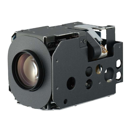
Page 5: Locations Of Controls
Locations of Controls Main Unit Front Back 1 Lens 2 CN902 jack 3 CN901 jack Left side Bottom 4 CN601 jack (for key SW) 5 TELE button 6 WIDE button S602 S601 7 Tripod screw holes When a tripod is used, please use 10 mm ( in.) screws to attach it to the camera. -
Page 6: Basic Functions
Overview of Functions VISCA commands are the basis of camera control. Timing Chart As VISCA Command processing can only be carried out one time in a Vertical cycle, it takes the maximum 1V cycle time for an ACK/Completion to be returned. If the Command ACK/Completion communication time can be cut shorter than the1V cycle time, then every 1V cycle can receive a Command. - Page 7 Zoom The FCB-EX980S/EX980SP/EX980/EX980P employs a 26 optical zoom lens combined with a digital zoom function; this camera allows you to zoom up to 312 . • Optical 26 , f = 3.5 to 91 mm (F 1.6 to F 3.8) The horizontal angle of view is approximately 54.2 degrees (wide end) to 2.2 degrees (tele end).
-
Page 8: White Balance
White Balance White Balance has the following modes, all of which can be set using VISCA Commands. • Auto White Balance This mode computes the white balance value output using color information from the entire screen. It outputs the proper value using the color temperature radiating from a black subject based on a range of values from 3000 to 7500K. - Page 9 AE – Manual The shutter speed (22 steps), iris (18 steps) and gain (16 steps) can be set freely by the user. AE – Bright The bright control function adjusts both gain and iris using an internal algorithm, according to a brightness level freely set by the user.
-
Page 10: Exposure Compensation
Exposure Compensation Exposure compensation is a function which offsets the internal reference brightness level used in the AE mode, by steps of 1.5 dB. Data Step Setting value 10.5 dB 9 dB 7.5 dB 6 dB 4.5 dB 3 dB 1.5 dB 0 dB –1... - Page 11 Camera ID The ID can be set up to 65,536 (0000 to FFFF). As this will be memorized in the nonvolatile memory inside, data will be saved regardless of whether it has been backed up. Effect It consists of the following functions. •...
-
Page 12: Title Display
Title Display The camera can be given a title containing up to 20 characters such as “ENTRANCE” or “LOBBY”. The position of the first character (horizontal, vertical) of the title, blinking state, and color can also be changed. Vposition Hposition 00: Does not blink Blink 01: Blinks... - Page 13 Privacy Zone Masking Function Privacy Zone masking protects private objects and areas such as house windows, entrances, and exits which are within the camera’s range of vision but not subject to surveillance. Privacy zone masking can be masked on the monitor to protect privacy.
- Page 14 Privacy Zone Setting Command List Command Set Command CAM_PrivacyZone SetMask Display SetMaskColor SetPanTiltAngle SetPTZMask Non_InterlockMask Grid On Grid Off CenterLineOn Privacy Zone Inquiry Command List Inquiry Command Command Packet Inquiry Packet CAM_Privacy 8x 09 04 77 FF DisplayInq CAM_PrivacyPan 8x 09 04 79 FF TiltInq CAM_Privacy 8x 09 04 7B mm FF y0 50 0p 0p 0p 0q 0q 0q 0r 0r...
- Page 15 Parameters mm: Mask setting list Mask Name mm (Hex) Mask Name Mask_A Mask_M Mask_B Mask_N Mask_C Mask_O Mask_D Mask_P Mask_E Mask_Q Mask_F Mask_R Mask_G Mask_S Mask_H Mask_T Mask_I Mask_U Mask_J Mask_V Mask_K Mask_W Mask_L Mask_X Note The priority order of the mask display is in the sequence from A (highest) to X (lowest).
- Page 16 Details of Setting Commands Set Mask Command: 8x 01 04 76 mm nn 0r 0r 0s 0s FF Parameters: Setting Mask See “mm: mask setting list” in “Parameters” on page 15. Selects new setting or resetting for the zone. See nn: Setting”...
-
Page 17: Alarm Function
Grid Use the grid displayed on the screen to set mask positions (see the figure below). By executing the Center Line On command, only the x and y axes of the center are displayed. Grids lines disappear. Alarm Function This function instructs the camera to detect movement within the monitoring area and then send an alarm signal automatically. - Page 18 ALARM Setting Command List Command Set Command CAM _ Alarm Set Mode Set Day Night Level VISCA Mode Code (pp) Details of Mode Set the internal focus position. When focus movement is detected, the detect signal is High. When focus goes back to the previous position, the detect signal is Low.
- Page 19 Flowchart of 12 Modes Function Mode “00” Set the Focus Position Hysteresis. Focus moves outside of the hysteresis. High level signal output Focus goes back to the previous position. Low level signal output Set to the factory preset Alarm On Focus Position into memory AE moves Focus...
- Page 20 Mode “01” Focus moves outside of the hysteresis. High level signal output * Repeat this loop until Alarm off. Update the Focus position data. Alarm On AE moves. AE does not move for a period of time. Low level signal output Basic Functions Focus Position into memory Hysteresis is set to the factory...
- Page 21 Mode “02” Set the AE level Hysteresis. AE moves AE moves outside of the hysteresis. High level signal output AE goes back to the previous level. Low level signal output Set to the factory preset AE Level into memory Alarm On Bright AE Level High...
- Page 22 Mode “03” * Repeat this loop until Alarm off. Alarm On AE moves. AE moves outside of the hysteresis. High level signal output AE does not move for a period of time. Low level signal output Update the AE level data Basic Functions AE level into memory Hysteresis is set to the factory...
- Page 23 Details of Mode “01”/”03" Alarm ON Hysteresis Focus Pos AE Level Signal level T1: Reset interval timer (5sec) T2: Detect timer (2sec) T3: High level signal count timer (2sec) Reset Reset Reset High Basic Functions Reset...
- Page 24 Mode “04” High output result of mode “00” High output result of mode “02” Mode “05” High output result of mode “00” High output result of mode “03” High output High output Basic Functions Low output Low output...
- Page 25 Basic Functions Mode “06” High output result of mode “01” High output result of mode “02” Low output High output Mode “07” High output result of mode “01” High output result of mode “03” High output Low output...
- Page 26 Mode “08” High output result of mode “00” High output result of mode “02” High output Mode “09” High output result of mode “00” High output result of mode “02” High output High output result of mode “02” High output High output High output result of mode “03”...
- Page 27 Mode “0A” High output result of mode “01” High output result of mode “02” High output Mode “0B” High output result of mode “01” High output result of mode “02” High output High output result of mode “02” High output High output High output result of mode “03”...
- Page 28 Day-Night Mode (Mode “0C”) Set the Day-Night Mode and the Day/ Night AE level. Alarm On AE move Brightness is higher than Day AE level Low level signal output High Bright AE level Night AE level Dark Signal level Setting by the VISCA Cmd. Starting distinction between Day and Night.
-
Page 29: Eclipse
Eclipse When designing the housing, refer to the dimensional allowance as shown in the figure below. Eclipse of the Lens The eclipse phenomenon occurs with the FCB-980/ 980P. This is because a sufficient amount of aperture is not available due to the CCD size and the lens structure of the FCB-980/980P. -
Page 30: Key Switch Circuitry
The circuitry shown below is an example. Note that all switches in the figure do not function in all models. For more information, refer to the command list, check functions on the camera, or contact your Sony dealer. S101 S112... -
Page 31: Key Function Specifications
Key Function Specifications Classification Name Function ZOOM WIDE Move ZOOM to WIDE side quickly. WIDE SLOW Move ZOOM to WIDE side slowly. TELE SLOW Move ZOOM to TELE side slowly. TELE FAST Move ZOOM to TELE side quickly. D-ZOOM DZOOM Turn on/off the mode for shifting from optical MAX to electronic ZOOM in combined mode. - Page 32 Classification Name Function FEATURE FREEZE Capture still image. Horizontal reversal REVERSE BLACK & Black-and-white output WHITE NEGA ART Negative art output MUTE Mute video output DISPLAY DISPLAY Display TITLE Title setting EXEC Confirm title/clock settings. UP/DOWN Data UP key (priority for AE mode, Bright, manual WB, title, and clock) DOWN Data DOWN key (priority for AE mode, Bright,...
-
Page 33: Initial Settings, Custom Preset And Backup
Initial Settings, Custom Preset and Backup Initial settings for the various functions of the FCB camera are indicated in the “Initial settings” column. The “Custom preset” column indicates whether the custom preset function can be used to store the settings. The function enables the stored settings to be recalled automatically when the camera is turned on. - Page 34 Mode/Position setting Title Display On/Off Title Setting Mask Setting Mask Display On/Off Mask Color Setting Alarm On/Off Alarm Mode Alarm Detect Level E-Flip On/Off Privacy Zone On/Off Privacy Zone Setting Key Lock On/Off Camera ID External Lock Mode V-Phase V-Phase Phase Inversion A circle “a”...
-
Page 35: Mode Condition
Basic Functions... - Page 36 Basic Functions...
- Page 37 Basic Functions...
-
Page 38: Command List
MALFUNCTION OR DAMAGE. THIS CONTROL PROTOCOL AND COMMAND LIST SHOULD BE USED WITH CAUTION. 1)VISCA is a protocol which controls consumer camcorders developed by Sony. “VISCA” is a trademark of Sony Corporation. Command List Overview of VISCA In VISCA, the device outputting commands, for example, a computer, is called the controller. - Page 39 VISCA Communication Specifications VISCA packet structure The basic unit of VISCA communication is called a packet. The first byte of the packet is called the header and comprises the sender’s and receiver’s addresses. For example, the header of the packet sent to the FCB camera assigned address 1 from the controller (address 0) is hexadecimal 81H.
- Page 40 Responses for commands and inquiries ACK message Returned by the FCB camera when it receives a command. No ACK message is returned for inquiries. Completion message Returned by the FCB camera when execution of commands or inquiries is completed. In the case of inquiry commands, it will contain reply data for the inquiry after the 3rd byte of the packet.
- Page 41 X = 1 to 7: FCB camera address (For inquiry packet) X = 9 to F: FCB camera address +8 (For reply packet) X0 50 FF 88 01 00 01 FF Description (0020: Sony) HHHH = Model ID 042E: FCB-EX980S 042F: FCB-EX980SP 0430: FCB-EX980...
- Page 42 VISCA Command/ACK Protocol Command Command Message General Command 81 01 04 38 02 FF (Example) 81 01 04 38 FF (Example) 81 01 04 38 02 FF (Example) 81 01 04 08 02 FF (Example) Inquiry Command 81 09 04 38 FF (Example) 81 09 05 38 FF (Example)
-
Page 43: Error Messages
VISCA Camera-Issued Messages ACK/Completion Messages Command Messages z0 4y FF (y:Socket No.) Completion z0 5y FF (y:Socket No.) z = Device address + 8 Error Messages Command Messages Syntax Error z0 60 02 FF Command Buffer Full z0 60 03 FF Command Canceled z0 6y 04 FF (y:Socket No.) -
Page 44: Fcb Camera Commands
FCB Camera Commands Command List (1/4) Command Set Command AddressSet Broadcast IF_Clear Broadcast CommandCancel CAM_Power CAM_Zoom Stop Tele(Standard) Wide(Standard) Tele(Variable) Wide(Variable) Direct CAM_DZoom Combine Mode Separate Mode Stop Tele(Variable) Wide(Variable) x1/Max Direct CAM_Focus Stop Far(Standard) Near(Standard) Far(Variable) Near(Variable) Direct Auto Focus Manual Focus Auto/Manual One Push Trigger... - Page 45 Command List (2/4) Command Set Command CAM_WB Auto Indoor Outdoor One Push WB Manual One Push Trigger CAM_RGain Reset Down Direct CAM_BGain Reset Down Direct CAM_AE Full Auto Manual Shutter Priority Iris Priority Bright CAM_SlowShutter Auto Manual CAM_Shutter Reset Down Direct CAM_Iris Reset...
- Page 46 Command List (3/4) Command Set Command CAM_Aperture Reset Down Direct CAM_LR_Reverse CAM_Freeze CAM_PictureEffect Neg.Art B&W CAM_PictureFlip CAM_ICR CAM_AutoICR CAM_Stabilizer CAM_Memory Reset Recall CAM_CUSTOM Reset Recall CAM_MemSave Write CAM_Display On/Off CAM_Title Title Set1 Title Set2 Title Set3 Title Clear CAM_Mute On/Off Command Packet Comments 8x 01 04 02 00 FF...
- Page 47 Command List (4/4) Command Set Command CAM_PrivacyZone SetMask Display SetMask Color SetPan TiltAngle SetPTZMask Non_InterlockMask GridOn GridOff CenterLineOn CAM_KeyLock CAM_IDWrite CAM_ExternalLock Line Lock CAM_VPhase Stop Down Up (Step) Down (Step) Reset Direct 0 degree 180 degree CAM_Alarm SetMode SetDayNight Level Alarm (Reply) CAM_ExternalLock Line Lock...
- Page 48 Inquiry Command List (1/2) Inquiry Command Command Packet CAM_PowerInq 8x 09 04 00 FF CAM_ZoomPosInq 8x 09 04 47 FF CAM_DZoomModeInq 8x 09 04 06 FF CAM_DZoomC/SModeInq 8x 09 04 36 FF CAM_DZoomPosInq 8x 09 04 46 FF CAM_FocusModeInq 8x 09 04 38 FF CAM_FocusPosInq 8x 09 04 48 FF CAM_FocusNearLimitInq...
- Page 49 Inquiry Command List (2/2) Inquiry Command Command Packet CAM_LR_ReverseModeInq 8x 09 04 61 FF CAM_FreezeModeInq 8x 09 04 62 FF CAM_PictureEffectModeInq 8x 09 04 63 FF CAM_PictureFlipModeInq 8x 09 04 66 FF CAM_ICRModeInq 8x 09 04 01 FF CAM_AutoICRModeInq 8x 09 04 51 FF CAM_StabilizerModeInq 8x 09 04 34 FF CAM_MemoryInq...
- Page 50 Block Inquiry Command List Lens Control System Inquiry Commands ... Command Packet 8x 09 7E 7E 00 FF Byte Comments Destination Address Source Address 0 Completion Message (50h) Zoom Position (HH) Zoom Position (HL) Zoom Position (LH) Zoom Position (LL) Byte Comments Focus Near Limit (H)
- Page 51 Camera Control System Inquiry Commands ... Command Packet 8x 09 7E 7E 01 FF Byte Comments Destination Address Source Address 0 Completion Message (50h) R Gain (H) Stabilizer (1: On, 0: Off) R Gain (L) B Gain (H) B Gain (L) Byte Comments WB Mode...
- Page 52 Other Inquiry Commands ... Command Packet 8x 09 7E 7E 02 FF Byte Comments Destination Address Source Address 0 Completion Message (50h) Auto ICR 1: On 0: Off Key Lock 1: On 0: Off Power 1:On 0:Off Stabilizer 1: On 0: Off ICR 1: On 0: Off Freeze 1:On 0:Off LR Reverse 1:On 0:Off...
- Page 53 Enlargement Function Query Command ... Command Packet 8x 09 7E 7E 03 FF Byte Comments Destination Address Source Address 0 Completion Message (50h) Digital Zoom Position (H) Digital Zoom Position (L) AF Activation Time (H) AF Activation Time (L) Byte Comments AF Interval Time (H) AF Interval Time (L)
- Page 54 VISCA Command Setting Values Exposure control (1/2) NTSC Shutter Speed 10000 6000 4000 3000 2000 1500 1000 Iris F1.6 F2.4 F2.8 F3.4 F4.8 F5.6 F6.8 F9.6 CLOSE Gain 10000 6000 3500 2500 1750 1250 1000 Command List 28 dB 26 dB 24 dB 22 dB 20 dB...
- Page 55 Exposure control (2/2) IRIS Bright F1.6 F1.6 F1.6 F1.6 F1.6 F1.6 F1.6 F1.6 F1.6 F1.6 F1.6 F1.6 F1.6 F1.6 F1.6 F2.4 F2.8 F3.4 F4.8 F5.6 F6.8 F9.6 CLOSE Exposure Comp. –1 –2 –3 –4 –5 –6 –7 Zoom Ratio and Zoom Position (for reference) GAIN 28 dB...
-
Page 56: Lens Control
Digital Zoom Combine mode FCB-EX980S/EX980SP: X26-NTSC Digital Zoom Digital Zoom Ratio Position Data 4000 5E00 6800 6D00 7000 7200 7380 7480 7580 7600 76C0 7700 FCB-EX980/EX980P: X26-NTSC/PAL Digital Zoom Digital Zoom Ratio Position Data 4000 6000 6A80 7000 7300 7540 76C0 7800 78C0... -
Page 57: Title Setting
Others R,B gain Aperture Title setting Vposition Hposition 00: Dose not blink Blink 01: Blinks Color 00~FF 00~0F 00 to 0A 00 to 17 À È White Yellow Ó Ú Violet Õ Ñ Cyan Green Å Blue ø Command List &... -
Page 58: Specifications
FCB-EX980S/EX980SP Picture elements FCB-EX980S: Approx. 630K pixels FCB-EX980SP: Approx. 740K pixels Horizontal resolution NTSC: 470 TV lines (WIDE end) PAL: 460 TV lines (WIDE end) Lens 26 zoom F= 3.5 mm (WIDE) to 91 mm (TELE), F1.6 to F3.8 Zoom movement speed (NTSC) Optical WIDE/Optical TELE 4.0 sec Optical WIDE/Digital TELE 5.9 sec... - Page 59 FCB-EX980/EX980P Picture elements FCB-EX980: Approx. 380K pixels FCB-EX980P: Approx. 440K pixels Horizontal resolution NTSC: 470 TV lines (WIDE end) PAL: 460 TV lines (WIDE end) Lens 26 zoom F= 2.5 mm (WIDE) to 91 mm (TELE), F1.6 to F3.8 Zoom movement speed (NTSC) Optical WIDE/Optical TELE 4.0 sec Optical WIDE/Digital TELE 6.0 sec...
- Page 60 Dimensions Front 55.3 (30.3) (25) 7-M2 Depth 3mm or less Bottom 8-M2 Depth 3mm or less 40.2 Right side Left side Tripod Screw. Depth 7mm or less (1/4-20UNC) Specifications 88.5 48.3 39.8 4-M2 Depth 3mm or less 85.2 S602 S601 2-M2 Depyh 3mm or less Back Unit: mm (inches)
- Page 61 Pin assignment CN902 1 2 3 4 CN901 9 8 7 CN901 Pin No. Name CMOS 5V (low: max 0.8V, high: min 2.0V) Read Data CMOS 5V (low: max 0.1V, high: min 4.4V) Send Data GND (for RxD&TxD) DC IN 9.0V±3V GND (for DC IN) VBS OUT...