
Related Manuals for HP 1420 Series


Summary of Contents for HP 1420 Series
- Page 1 HP 1420 Gigabit Ethernet Switch Series Getting Started Guide 5998-5751 Part number: 5998-5751 Document version: 5W100-20141118...
- Page 2 The only warranties for HP products and services are set forth in the express warranty statements accompanying such products and services. Nothing herein should be construed as constituting an additional warranty.
-
Page 3: Table Of Contents
Connecting the AC power cord ··························································································································· 10 Verifying the installation ················································································································································ 10 Support and other resources ····································································································································· 11 Contacting HP ································································································································································ 11 Subscription service ·············································································································································· 11 Related information ························································································································································ 11 Documents ······························································································································································ 11 ... -
Page 4: Preparing For Installation
IMPORTANT: For regulatory identification purposes, the switches are assigned Regulatory Model Numbers (RMNs). The RMNs should not be confused with the marketing name HP 1420, or the product codes. Safety recommendations To avoid any equipment damage or bodily injury, read the following safety recommendations before installation. -
Page 5: Examining The Installation Site
Examining the installation site The switches must be used indoors. You can mount your switch in a rack, on a horizontal surface, on a wall, or under a table. Make sure the following requirements are met: • A minimum of 5 cm (1.97 in) of clearance is reserved at the air inlet and outlet vents for ventilation. The rack has a good ventilation system and the air inlet and outlet vents are not blocked when the •... -
Page 6: Emi
Maximum concentration (mg/m 0.01 All electromagnetic interference (EMI) sources, from outside or inside of the switch and application system, adversely affect the switch in the following ways: A conduction pattern of capacitance coupling. • Inductance coupling. • • Electromagnetic wave radiation. Common impedance (including the grounding system) coupling. -
Page 7: Installing The Switch
WARNING! Before installing or moving the switch, remove the power cord. You can install an HP 1420 switch in a 19-inch rack, on a horizontal surface, on a wall, or under a table. Rack mounting Wear an ESD wrist strap and make sure it makes good skin contact and is reliably grounded. - Page 8 Figure 3 Attaching Type-A mounting brackets to the rack post Figure 4 Attaching Type-B mounting brackets to the rack post...
-
Page 9: Horizontal Surface Mounting
Wall mounting Only the HP 1420- 1 6G switch can be installed on a wall. The type of screws used to mount the switch on the wall depends on the wall type. This section uses a concrete wall as an example. - Page 10 Figure 7 Hole spacing Insert one wall anchor into each hole until the anchors are flush with the wall surface. Drive one screw into each wall anchor, and tighten the screws just enough to keep it secure in the wall anchor. Leave a minimum clearance of 1.5 mm (0.06 in) between the base of the screw head and the wall anchor so the switch can hang on the screws securely.
-
Page 11: Under-Table Mounting
Regularly inspect the installation of the switch to ensure that the switch remains securely anchored and unobstructed. Only the HP 1420- 1 6G switch supports under-table mounting. The wall mounting screws (provided) can be used when you mount the switch under a table. -
Page 12: Installing The Sfp/Sfp+ Transceiver Module And Optical Fibers
• • The fiber ports on the HP 1420-24G-2SFP Switch operate in autonegotiation mode. For the link between the switch and the peer device to operate correctly, verify that the fiber ports on the peer device also operate in autonegotiation mode. -
Page 13: Connecting The Ac Power Cord
Connecting the AC power cord Wear an ESD wrist strap and make sure it makes good skin contact and is reliably grounded. (Optional.) Connect one end of the grounding cable to the grounding screw on the rear panel, and connect the other end to the ground. Make sure the correct power source is used. -
Page 14: Support And Other Resources
Related information Documents To find related documents, browse to the Manuals page of the HP Business Support Center website: http://www.hp.com/support/manuals For related documentation, navigate to the Networking section, and select a networking category. •... -
Page 15: Conventions
Conventions This section describes the conventions used in this documentation set. Command conventions Convention Description Boldface Bold text represents commands and keywords that you enter literally as shown. Italic Italic text represents arguments that you replace with actual values. Square brackets enclose syntax choices (keywords or arguments) that are optional. Braces enclose a set of required syntax choices separated by vertical bars, from which { x | y | ... - Page 16 Network topology icons Represents a generic network device, such as a router, switch, or firewall. Represents a routing-capable device, such as a router or Layer 3 switch. Represents a generic switch, such as a Layer 2 or Layer 3 switch, or a router that supports Layer 2 forwarding and other Layer 2 features.
-
Page 17: Appendix A Chassis Views And Technical Specifications
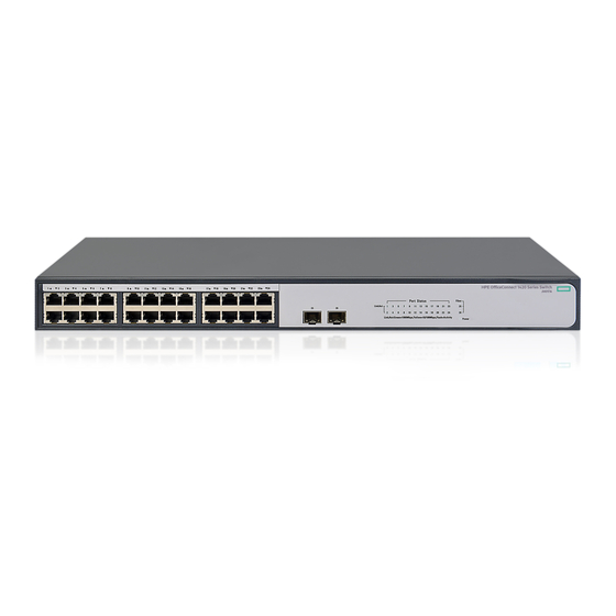
Appendix A Chassis views and technical specifications Chassis views 1420-16G Figure 14 1420-16G front panel (1) 10/100/1000BASE-T copper ports (2) Copper port LEDs (3) Power LED Figure 15 1420-16G rear panel (1) Grounding screw (2) AC power receptacle 1420-24G-2SFP Figure 16 1420-24G-2SFP front panel (1) 10/100/1000BASE-T copper ports (2) 100/1000BASE-X SFP fiber ports (3) Copper port LEDs... -
Page 18: 1420-24G-2Sfp+ 10G Uplink
Figure 17 1420-24G-2SFP rear panel (1) Grounding screw (2) AC power receptacle 1420-24G-2SFP+ 10G Uplink Figure 18 1420-24G-2SFP+ 10G Uplink front panel (1) 10/100/1000BASE-T copper ports (2) 1000BASE-X SFP/10GBASE-SR/LR SFP+ ports (3) Copper port LEDs (4) Power LED (5) Fiber port LEDs Figure 19 1420-24G-2SFP+ 10G Uplink rear panel (1) Grounding screw (2) AC power receptacle... -
Page 19: Technical Specifications
Figure 21 1420-24G-PoE+ (124W) rear panel (1) Grounding screw (2) AC power receptacle Technical specifications Chassis dimensions and weights Chassis Dimensions (H x W x D) Maximum weight 1420-16G 44 × 266 × 162 mm (1.73 × 10.47 × 6.38 in) 1.2 kg (2.65 lb) 1420-24G-2SFP 44 ×... -
Page 20: Power Specifications
Power specifications AC input voltage specifications Chassis Rated voltage range All chassis 100 VAC to 240 VAC @ 50 Hz or 60 Hz Power consumption specifications for non-PoE switches Chassis Min. power consumption Max. power consumption 1420-16G 6.8 W 12 W 1420-24G-2SFP 18 W 1420-24G-2SFP+ 10G Uplink... -
Page 21: Appendix B Leds
Appendix B LEDs Power LED Table 4 Power LED description Status Description Steady green The switch is powered on and the power supply is operating correctly. The switch is powered on and is performing the self-test. The switch is faulty if the LED Flashing green flashes green for five seconds. -
Page 22: Fiber Port Leds
NOTE: A port with a smaller port ID has a higher priority for getting power. When the PoE power reaches the guard band and a new port requires power, the switch compares the port IDs and performs one of the following actions: Does not supply power to the new port if the ID of the new port is greater than IDs of all existing ports. -
Page 23: Appendix C Troubleshooting
Appendix C Troubleshooting Table 10 describes the troubleshooting methods for common issues that you might encounter while using and managing the switch. If a problem persists, contact HP Support. Table 10 Troubleshooting methods Symptom Troubleshooting method Verify that the correct power source is used and the power cords are correctly connected.