Table of Contents
Quick Links
Table of Contents

Related Manuals for Siemens SIMATIC PN/BACnet LINK


Summary of Contents for Siemens SIMATIC PN/BACnet LINK
- Page 2 ___________________ Introduction ___________________ Safety instructions ___________________ SIMATIC System overview ___________________ Functions Network transitions PN/BACnet LINK ___________________ Application planning ___________________ Mounting/Extending Operating Instructions ___________________ Connecting ___________________ Commissioning ___________________ Configuring / Programming ___________________ Diagnostics ___________________ Maintenance and service ___________________ Technical specifications ___________________ Appendix 10/2017 A5E39895543-AA...
- Page 3 Note the following: WARNING Siemens products may only be used for the applications described in the catalog and in the relevant technical documentation. If products and components from other manufacturers are used, these must be recommended or approved by Siemens. Proper transport, storage, installation, assembly, commissioning, operation and maintenance are required to ensure that the products operate safely and without any problems.
-
Page 4: Table Of Contents
Table of contents Introduction ............................. 7 Preface ............................. 7 Documentation guide ....................... 8 Safety instructions........................... 9 Safety instructions ........................9 Security information ....................... 11 IT security ..........................11 System overview ........................... 12 Field of application ......................... 12 Features ..........................13 System configuration ...................... - Page 5 Table of contents Application planning ..........................45 Installation guidelines......................45 Installation location ......................... 46 Transportation ......................... 49 Storage ........................... 49 Scope of delivery ........................49 Mounting/Extending ..........................50 Installing the device ........................ 50 Connecting ............................52 Safety instructions and guidelines ..................52 Potential ratios ........................
- Page 6 Contact address ........................91 Licenses ..........................91 Service & Support ........................92 A.4.1 Technical Support ........................92 A.4.2 Siemens Industry Online Support ..................92 A.4.3 Online catalog and ordering system ..................92 Glossary ............................... 93 Index ..............................95 PN/BACnet LINK...
-
Page 7: Introduction
● Knowledge of working with the PROFINET fieldbus ● Sound knowledge of the BACnet/IP communication protocol ● General knowledge in the field of automation technology ● General knowledge of communication networks Trademarks SIMATIC is a registered trademark of Siemens AG. ® History Edition Remarks 10/2017... -
Page 8: Documentation Guide
Introduction 1.2 Documentation guide Naming conventions The following terms are also used in this documentation instead of the full product name "SIMATIC PN/BACnet LINK": ● "PN/BACnet LINK" ● "Device" Documentation guide Below you will find a list of documents which supplement these operating instructions for the PN/BACnet LINK and which are available on the Internet. -
Page 9: Safety Instructions
If the device is used in a manner other than the one specified by Siemens, the protection offered by the device might be impaired. See also the section "Legal notices" at the beginning of this manual. - Page 10 Safety instructions 2.1 Safety instructions Safety information WARNING Connection only over safety extra-low voltage / protective extra-low voltage May cause death or serious injury The device is designed for operation using directly connectable safety extra-low voltage (SELV) with safe electrical separation according to IEC 60950-1 / EN 60950-1 / VDE 0805-1 or IEC 61131-2 / EN 61131-2 / DIN EN 61131-2.
-
Page 11: Security Information
In order to protect plants, systems, machines and networks against cyber threats, it is necessary to implement – and continuously maintain – a holistic, state-of-the-art industrial security concept. Siemens’ products and solutions only form one element of such a concept. Customer is responsible to prevent unauthorized access to its plants, systems, machines and networks. -
Page 12: System Overview
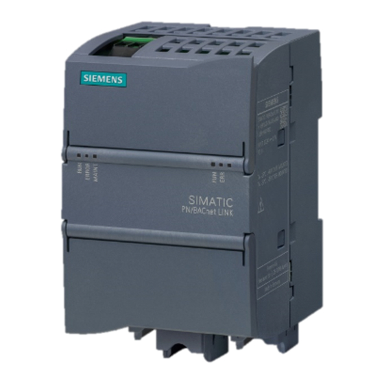
System overview Field of application Figure 3-1 SIMATIC PN/BACnet LINK The PN/BACnet LINK is a communication gateway and enables the connection of SIMATIC controllers to the BACnet/IP fieldbus over PROFINET. This connection enables the exchange of information and data between PROFINET and BACnet/IP. -
Page 13: Features
System overview 3.2 Features Features General features ● 1 BACnet port (Fast Ethernet, RJ45). The maximum transmission rate is 100 Mbps. ● The PN/BACnet LINK supports BACnet/IP according to DIN EN ISO16484-5 and Addendum ANSI/ASHRAE Standard 135-2012. ● BACnet/IP profile: B-GW (BACnet gateway) ●... - Page 14 System overview 3.2 Features Quantity structure for configuring the PN/BACnet LINK Limits specified by the PN/BACnet LINK ● The sum of all server objects and the object references on the BACnet devices must not exceed 1000 (e.g. 400 binary inputs on the server and 600 referenced binary outputs). ●...
-
Page 15: System Configuration
System overview 3.3 System configuration System configuration System configuration The following figure shows a basic system configuration with a PN/BACnet LINK as a communication gateway between a PROFINET network and a BACnet/IP network. Figure 3-2 System configuration with PN/BACnet LINK Purpose and function of the system components The PN/BACnet LINK enables the connection of PROFINET to BACnet/IP. -
Page 16: System Requirements
System overview 3.4 System requirements System requirements System requirements ● PN/BACnet LINK ● Controller: Supported are SIMATIC S7-1200, SIMATIC S7-1500, SIMATIC ET 200SP, SIMATIC OpenController ● 24 V power supply ● BACnet/IP bus ● PROFINET bus ● Windows PC (for configuring, commissioning and diagnostics) ●... -
Page 17: Design
System overview 3.5 Design Design PN/BACnet LINK design The figure below shows the arrangement of the connection and display elements on the PN/BACnet LINK. The figure shows the device without a top and bottom enclosure cover. Design ① 24 V DC + functional grounding ②... -
Page 18: Functions
Functions BACnet objects 4.1.1 Overview The PN/BACnet LINK can be used both as a BACnet client and as a BACnet server. As a client, PN/BACnet LINK is the active communication partner, that is, it requests data from other communication partners (BACnet servers). As a server, PN/BACnet LINK provides data that is used by other communication users (BACnet clients). - Page 19 Functions 4.1 BACnet objects Communication paths of BACnet server BACnet objects of the type "Binary input (BI) and "Analog input" (AI) are inputs on the BACnet side. The values are written from the S7 side to the "Present_Value" property of the corresponding input object.
- Page 20 Functions 4.1 BACnet objects Communication paths of BACnet client The PN/BACnet LINK reads the values of the corresponding "Present_Value" properties and transfers them to the S7 controller via references to input objects. The PN/BACnet LINK writes values which come from the S7 controller to the associated "Present_Value" properties of the corresponding objects via references to output objects.
-
Page 21: Server Objects
Functions 4.1 BACnet objects 4.1.2 Server objects Server objects are BACnet objects which the PN/BACnet LINK contains itself. When they are configured, full BACnet objects are written with the required properties. The PN/BACnet LINK supports the following Server objects: ● Device ●... -
Page 22: Device Object
PN/BACnet LINK and from which source the associated values originate. Property Data source Value Access Object_Identifier Configuration Object_Name Configuration Object_Type Fixed System_Status Dynamic Vendor_Name Fixed Siemens AG Vendor_Identifier Fixed Model_Name Fixed PN/BACnet LINK Firmware_Revision Fixed e.g. V1.0.0-xxxx xxxx = 4-digit build number Application_Software_Version Configuration Protocol_Version Fixed Protocol_Revision... -
Page 23: Binary Input
Functions 4.1 BACnet objects All the properties listed in the table can only be read from the BACnet side. Writing of these properties from the BACnet side is not possible. Note The device object must be configured even if only client object references are required, since this object must be present in every BACnet device. -
Page 24: Binary Output
Functions 4.1 BACnet objects 4.1.2.3 Binary output The PN/BACnet LINK supports the object type "Binary output" as server. BACnet objects of the type "Binary output" are outputs on the BACnet side. They are read from the S7 side. Binary output properties The following table shows which properties are supported for the object type "Binary output"... -
Page 25: Analog Input
Functions 4.1 BACnet objects 4.1.2.4 Analog input The PN/BACnet LINK supports the object type "Analog input" as server. BACnet objects of the type "Analog input" are inputs on the BACnet side. They are written from the S7 side. Analog input properties The following table shows which properties are supported for this object type of the PN/BACnet LINK and from which source the associated values are filled. -
Page 26: Analog Output
Functions 4.1 BACnet objects 4.1.2.5 Analog output The PN/BACnet LINK supports the object type "Analog output" as server. BACnet objects of the type "Analog output" are outputs on the BACnet side. They are read from the S7 side. Analog output properties The following table shows which properties are supported for this object type of the PN/BACnet LINK and from which source the associated values are filled. -
Page 27: Client Object References
Functions 4.1 BACnet objects 4.1.3 Client object references Client object references are references to BACnet objects which are located in other BACnet devices. If the PN/BACnet LINK does not require any server objects, which means only client object references are configured, the device object must still be configured. Supported object references The PN/BACnet LINK supports object references to the following BACnet objects: ●... -
Page 28: Supported Bacnet Services (Bibb)
Functions 4.1 BACnet objects 4.1.4 Supported BACnet services (BIBB) Supported BIBB BIBB Description DS-COV-A The PN/BACnet LINK works as a Client and is able to register with other objects for notification when a value changes. The service "SubscribeCOV" is used for this. -
Page 29: State Model
Functions 4.2 State model State model The configuration made in HSP is transmitted to the PB/BACnet LINK in the startup phase of the S7 controller. This configuration information is stored in the S7 controller and not in the PN/BACnet LINK. Controlling the server and client status Client functionality The data transfer is controlled via a control byte (Page 32) which is transmitted cyclically by... - Page 30 Functions 4.2 State model PN/BACnet LINK states The status of the PN/BACnet LINK is influenced by the status of the PROFINET connection and the status of the S7 controller. The following table shows the dependency of the PN/BACnet LINK state from the status of the PROFINET connection and from the state of the S7 controller.
- Page 31 Functions 4.2 State model S7 controller goes into STOP The PN/BACnet LINK state changes to STOP operating state. (NON_OPERATIONAL). All BACnet Server objects are set to "Out_Of_Service" = • TRUE. "System_Status" property in the device object is set to • NON_OPERATIONAL.
-
Page 32: Cyclic Data Exchange Between Controller And Pn/Bacnet Link
Functions 4.3 Cyclic data exchange between controller and PN/BACnet LINK Cyclic data exchange between controller and PN/BACnet LINK 4.3.1 Data exchange between controller and PN/BACnet LINK Cyclic data exchange The cyclic data exchange between S7 controller and the PN/BACnet LINK is performed via PROFINET IO. - Page 33 Functions 4.3 Cyclic data exchange between controller and PN/BACnet LINK Status and control information of BACnet server The PN/BACnet LINK cyclically transmits the following status information to the S7 controller: Table 4- 1 Current status of the server in the PN/BACnet LINK (1 byte input address) Meaning Value Remarks...
- Page 34 Functions 4.3 Cyclic data exchange between controller and PN/BACnet LINK Status and control information of BACnet client The PN/BACnet LINK cyclically transmits the following status information to the S7 controller: Table 4- 3 Status of the client functionality (1 byte input address) Meaning Value Remarks...
- Page 35 Functions 4.3 Cyclic data exchange between controller and PN/BACnet LINK Status information on BACnet objects The status information of the BACnet objects on the PN/BACnet LINK is exchanged with the S7 controller via the process image. Server objects With server objects, the PN/BACnet LINK writes the status information transferred by the S7 controller to the property "Status_Flags"...
-
Page 36: Data Exchange Between Pn/Bacnet Link And Other Bacnet Devices
Functions 4.4 Data exchange between PN/BACnet LINK and other BACnet devices Effect of the S7 communication state on the status information of server objects For server objects, the S7 controller can only affect the OUT_OF_SERVICE status flag. The other status flags are set completely by the PN/BACnet LINK. The state of the OUT_OF_SERVICE status flag which is specified by the S7 controller can be overwritten by internal states of the PN/BACnet LINK. -
Page 37: Data Transfer As Server
Functions 4.4 Data exchange between PN/BACnet LINK and other BACnet devices Reading values For read values, you can determine whether they are read cyclically or if a registration for a message is to take place in case of value change (COV). If "Registration for value change"... -
Page 38: Acyclic Data Exchange
Functions 4.5 Acyclic data exchange Acyclic data exchange 4.5.1 Acyclic reading and writing of properties of BACnet objects from the S7 user program Using the acyclic PROFINET IO services RDREC (write data record) and WRREC (write data record), individual "ReadProperty" and "WriteProperty" accesses can be triggered on any BACnet properties. - Page 39 Functions 4.5 Acyclic data exchange ReadProperty For a "ReadProperty", the data record must contain the corresponding parameters for the service. The result is located in a data record, which must then be read. Table 4- 5 WRREC (write data record) - data record structure for "ReadProperty" service Element Type Meaning...
- Page 40 Functions 4.5 Acyclic data exchange WriteProperty For a "WriteProperty", in addition to the parameters required for "ReadProperty", the data record must also contain the property value and the priority of the write job. Table 4- 7 WRREC (Write data record) - RecordWrite data record structure for WriteProperty service Element Type...
- Page 41 Functions 4.5 Acyclic data exchange Error messages If an error occurs in the PROFINET connection during an acyclic property access triggered by a data record, then the element "PNresp" of the associated reply data record contains the cause of the error. Table 4- 9 PROFINET error numbers (PNresp) Error ID...
-
Page 42: Monitoring Functions
Functions 4.6 Monitoring functions Monitoring functions Diagnostics with activated device monitoring For monitoring of configured BACnet devices, the PN/BACnet LINK cyclically requests the property "System_Status" of the devices in question. The cycle time with which the PN/BACnet LINK reads out the property "System_Status" from other devices can be configured. -
Page 43: Response To Errors
Functions 4.7 Response to errors Response to errors Diagnostic resource The device provides various tools to isolate the cause. These tools are listed below: Diagnostic resource Description Examples of possible causes of error LED display The PN/BACnet LINK signals its state with the Device fault •... - Page 44 Functions 4.7 Response to errors PROFINET network error If the PN/BACnet LINK loses the PROFINET connection, the PN/BACnet LINK performs the following actions: ● The PN/BACnet LINK sets the OUT_OF_SERVICE status bits of all server objects. ● The PN/BACnet LINK allocates the system state in the device object with NON_OPERATIONAL.
-
Page 45: Application Planning
Application planning Installation guidelines General installation guidelines The following guidelines must be observed when installing and connecting the PN/BACnet LINK: ● When connecting the PN/BACnet LINK, make sure that you observe all applicable and legally binding standards. Adhere to the relevant national and regional regulations when installing and operating the device. -
Page 46: Installation Location
Application planning 5.2 Installation location Installation location Selection of the installation site / installation You can install the PN/BACnet LINK either in a control panel or on a standard mounting rail: Installation in control cabinet / device connection box NOTICE The device is intended for installation in a control cabinet or in a device connection box. - Page 47 Application planning 5.2 Installation location Permitted mounting positions and permitted ambient temperature The table below show the permitted temperature range for the different mounting positions. Mounting position Permitted ambient temperature Horizontal -25 ... +60 °C Vertical -25 ... +55 °C Lying -25 ...
- Page 48 Application planning 5.2 Installation location Minimum spacing The PN/BACnet LINK is designed for natural heat dissipation through convection. Therefore observe sufficient clearances: ● For horizontal mounting position: At least 35 mm above and below the PN/BACnet LINK ● For vertical mounting position: At least 35 mm to the left and right of the PN/BACnet LINK Provide sufficient space for the connection of supply voltage, Ethernet and BACnet bus.
-
Page 49: Transportation
Application planning 5.3 Transportation Electromagnetic compatibility (EMC) / overvoltage protection NOTICE Damage to the device Inadequately dimensioned overvoltage protection can result in severe damage to the device. Always ensure, therefore, that the overvoltage protection is adequate (see Chapter 24 V DC power supply (Page 55)). Transportation The devices must be transported in a clean and dry state, preferably in their original packaging. -
Page 50: Mounting/Extending
Mounting/Extending Installing the device The PN/BACnet LINK can be mounted to a 35 mm standard mounting rail according to DIN EN 60715 or installed on a control panel. Information on the selection of the location of use as well as reliable mounting positions and minimum clearances is available in the section Installation location (Page 46). - Page 51 Mounting/Extending 6.1 Installing the device Mounting to a control panel Preparations ● Drill holes (M4). The dimensions for the drill holes are available in the figure below. ● Remove the retaining collar on the BACnet connection. This is required so that you can screw in the fixing screw later.
-
Page 52: Connecting
Connecting Safety instructions and guidelines Safety information WARNING Connection only over safety extra-low voltage / protective extra-low voltage May cause death or serious injury The device is designed for operation using directly connectable safety extra-low voltage (SELV) with safe electrical separation according to IEC 60950-1 / EN 60950-1 / VDE 0805- 1 or IEC 61131-2 / EN 61131-2 / DIN EN 61131-2. - Page 53 Connecting 7.1 Safety instructions and guidelines Wiring guidelines When wiring the PN/BACnet LINK, observe the wiring guidelines of your automation system (e.g. SIMATIC S7-1200, SIMATIC S7-1500, SIMATIC ET 200SP). Also observe the installation instructions and configuration guidelines for routing of the PROFINET cables.
-
Page 54: Potential Ratios
Connecting 7.2 Potential ratios Potential ratios Electrical isolation Electrical isolation for the PN/BACnet LINK exists between the following switching components: ● The signals of the PROFINET interfaces are galvanically isolated from each other, from the electronics or 24 V supply voltage and from the fieldbus interfaces. ●... -
Page 55: Dc Power Supply
Connecting 7.3 24 V DC power supply 24 V DC power supply 24 V DC power supply The connection of the external 24 V power supply and the functional earth connection takes place via a 3-pin screw-type terminal. It is located below the top housing cover (see Design (Page 17)). -
Page 56: Connecting The Functional Ground
Connecting 7.4 Connecting the functional ground External lightning protector An external lightning protector can be installed in the 24 V DC supply line to protect against powerful pulses on the supply lines: We recommend the Dehn Blitzductor BXT ML2 BD 180, article number 920 247 (on basis BXT BAS) or an equivalent protection element. -
Page 57: Connecting Profinet
Ethernet connectors are installed on the bottom part of the housing of the PN/BACnet LINK in the delivery state. These retaining collars are intended for the Siemens FastConnect connectors. NOTICE Make sure you observe the minimum bending radius of the Ethernet cable; otherwise the shield effect of the cable shield may be impaired. -
Page 58: Connecting Bacnet Bus
To increase the mechanical stability, a retaining collar for the BACnet connector is installed on the bottom part of the housing of the PN/BACnet LINK in the delivery state. This retaining collar is intended for the Siemens FastConnect connectors. PN/BACnet LINK Operating Instructions, 10/2017, A5E39895543-AA... -
Page 59: Commissioning
1. Checking in the TIA Portal whether the "PN/BACnet LINK" module exists in the hardware catalog. If necessary, download and install the HSP "HSP0214 PN/BACnet LINK" from Siemens Service&Support (http://support.automation.siemens.com). 2. Assign a PROFINET device name and an IP address for the PN/BACnet LINK. -
Page 60: Configuring / Programming
Configuring / Programming Overview The PN/BACnet LINK is configured in the TIA Portal. Configuration mainly comprises the following steps: 1. Dragging PN/BACnet LINK from the HW catalog to the project 2. S7 controller and PN/BACnet LINK via PROFINET 3. Setting the PROFINET-specific parameters 4. -
Page 61: Tia Portal Devices & Networks
Configuring / Programming 9.2 TIA Portal Devices & Networks TIA Portal Devices & Networks TIA Portal: Devices & networks Follow these steps: ① 1. Select the PN/BACnet LINK with its specific article number from the HW catalog . The PN/BACnet LINK appears in the "Devices & networks" window. 2. -
Page 62: Configuring The Bacnet/Ip Interface
Configuring / Programming 9.3 Configuring the BACnet/IP interface Configuring the BACnet/IP interface Communication settings for the BACnet/IP interface ① 1. Enter the communication settings for the BACnet/IP protocol Specify the standard gateway of the BACnet subnet in which the PN/BACnet LINK is located as the default gateway. -
Page 63: Configuring A Bacnet Server
Configuring / Programming 9.4 Configuring a BACnet server Note If the foreign device registration fails with the configured BBMD after the specified number of retries, the PN/BACnet LINK cannot exchange data via BACnet. Possible causes of a registry failure may be, for example: Connection interruption, BBMD out of service, BBMD rejects the registration. - Page 64 Configuring / Programming 9.4 Configuring a BACnet server Configuring a device object The device object represents the PN/BACnet LINK as a device on the BACnet side. Vendor_Name and Model are fixed and cannot be changed. Figure 9-4 Device object Defining I/O objects In this dialog, you create new I/O objects, namely BACnet objects and can edit or delete existing I/O objects.
- Page 65 Configuring / Programming 9.4 Configuring a BACnet server Define I/O object - analog input example Figure 9-6 Analog input Note If you specify the value "0" as the change of value increment, the value of "Present_Value" is constantly transmitted to non-existing COV subscribers even when it has not changed. Exporting EDE data You can export the description of the I/O objects defined in PN/BACnet LINK and the device object as an .EDE file in *.csv format.
-
Page 66: Configure Bacnet Client
Configuring / Programming 9.5 Configure BACnet client Check the status address and the control address On the "Status and control address" page, you can see the addresses in the process image that contain the status byte and the control byte for the sever functionality. (see Data exchange between controller and PN/BACnet LINK (Page 32)). - Page 67 Configuring / Programming 9.5 Configure BACnet client Configuring monitoring You set client-specific monitoring parameters on this page. 1. You enable the monitoring of configured BACnet devices by setting a check mark. 2. Specify the desired monitoring interval. See section Monitoring functions (Page 42). Figure 9-9 Monitoring The monitoring interval set here applies globally for all BACnet devices, for which...
-
Page 68: Configuring References To Bacnet Devices
Configuring / Programming 9.5 Configure BACnet client Check status and control address On the "Status and control address" page, you can see the addresses in the process image that contain the status byte and the control byte for the client functionality. Adapting I/O addresses The start and end addresses of the input and output data of the BACnet Client can be set via the "I/O addresses"... -
Page 69: Import Ede File
Configuring / Programming 9.5 Configure BACnet client 9.5.2.1 Import EDE file An EDE file contains the devices available in a BACnet network along with their objects and services. After importing such a file, in the HSP you can specify which of the PN/BACnet LINK I/O objects contained therein should exchange data. - Page 70 Configuring / Programming 9.5 Configure BACnet client ① 3. Use the check boxes to specify the device objects to be transferred. The hierarchy ② arrow indicates that I/O objects are contained in the BACnet device. By clicking on the arrow, you can display the assigned I/O objects and select or deselect individual I/O objects.
-
Page 71: Find Bacnet Device
Configuring / Programming 9.5 Configure BACnet client 9.5.2.2 Find BACnet device 1. By clicking on the "Find BACnet devices..." button, the corresponding dialog opens. Figure 9-13 Find BACnet device ① 2. You can use a filter to limit and refine searches in the BACnet/IP network. You can specify a vendor ID and a value range in which the device instance IDs should lie. -
Page 72: Creating Object References Manually
Configuring / Programming 9.5 Configure BACnet client ③ 4. Use the check boxes to specify the BACnet device objects to be transferred. ④ The hierarchy arrow indicates that I/O objects are contained in the BACnet device. By clicking on the arrow, you can display the assigned I/O objects and select or deselect individual I/O objects. - Page 73 Configuring / Programming 9.5 Configure BACnet client Defining I/O object references You can now configure references to their I/O objects for each BACnet device that is created. The configured references to I/O objects of the BACnet device are mapped as input and output data in the corresponding process images on the PROFINET side.
- Page 74 Configuring / Programming 9.5 Configure BACnet client 5. Subscription for change of value (COV): Here, you define whether the BACnet client is to register for a notification of changes in the value of the corresponding BACnet device (server) and specify the necessary parameters. Defining I/O object references - binary input example Figure 9-16 Defining I/O object references - binary input example...
-
Page 75: Checking And Compiling The Configuration
Configuring / Programming 9.6 Checking and compiling the configuration Checking and compiling the configuration Checking / adapting I/O addresses If necessary, you must adapt the I/O addresses assigned automatically by the TIA Portal. This is possible, for example, in the "Device overview" window. Here you can also find the I/O addresses used by the slots. -
Page 76
Configuring / Programming 9.7 Programming Name diagram of the created PLC tags Module/ IO data Name diagram Data S7 address Submodule type mnemonic BACnet client Prefix:
. ByteAdr ClientStatus .ClientStatus Bool %I< >.0 ByteAdr ClientControl .ClientControl Bool %Q< >.0 BACnet server Prefix: . ... -
Page 77: Diagnostics
Diagnostics 10.1 Status LEDs 10.1.1 Operating state of the PN/BACnet LINK / PROFINET diagnostics The LEDs for visualizing the operating states of the PN/BACnet LINK and the PROFINET ports are located on the front of the housing. Figure 10-1 Status LEDs – Operating state of the PN/BACnet LINK / PROFINET diagnostics PN/BACnet LINK Operating Instructions, 10/2017, A5E39895543-AA... - Page 78 Diagnostics 10.1 Status LEDs RUN LED ERROR MAINT Operating Description state Power-up test / Seri- For approximately 1 second: LED • ous error test during startup Longer than 1 second: HW error • detected during power-up test or other serious error System run-up System not completely booted yet •...
-
Page 79: Connection Status Bacnet Bus
Diagnostics 10.1 Status LEDs 10.1.2 Connection status BACnet bus Connection status BACnet bus The PN/BACnet LINK signals its state with the BACnet LEDs on the front of the housing. Figure 10-2 Status LEDS BACnet bus Table 10- 1 Behavior of the RUN LED RUN LED Meaning Note... -
Page 80: Connection Status Of Ethernet Interfaces
Diagnostics 10.1 Status LEDs Note If the server and client are configured, then the RUN LED indicates whether it is the operating state of the server or that of the client which keeps the RUN LED in the "Off" state. If required, this detailed information can be found in the corresponding status byte in the cyclic I/O image. -
Page 81: Diagnostic Messages To The S7 Controller
Diagnostics 10.2 Diagnostic messages to the S7 controller 10.2 Diagnostic messages to the S7 controller 10.2.1 Events that trigger a diagnostic message Diagnostics The PN/BACnet LINK sends diagnostic information to the S7 controller with the usual PROFINET methods. The following table provides an overview of ●... - Page 82 Diagnostics 10.2 Diagnostic messages to the S7 controller Event text Event for triggering Possible remedy BACnet object not available Defective configuration for the Checking the configuration for the – BACnet object object and whether the BACnet object in question exists with the Object Identifier {1:x}: Error required permissions and whether while accessing the object...
- Page 83 Diagnostics 10.2 Diagnostic messages to the S7 controller Example The following figure shows an example of a diagnostic message with object identifier. The object identifier is output in hexadecimal form. "BACnet object not available – object identifier 400003h: Error while accessing the object". Meaning: An error occurred when accessing the object with object type "Analog Output"...
-
Page 84: Maintenance And Service
Maintenance and service 11.1 Firmware update Procedure 1. Set the S7 CPU to STOP mode. 2. Start the update of the PN/BACnet LINK in the TIA Portal. Depending on the configuration in the TIA Portal, the PN/BACnet LINK resumes running on its own after a successful update and waits for configuration information from the S7 controller. -
Page 85: Replacing The Pn/Bacnet Link
There is no provision for returning the device to Siemens. For further questions regarding disposal and recycling, please contact your local Siemens contact. You will find the contact details in our database on the Internet at: http://www.automation.siemens.com/partner... -
Page 86: Technical Specifications
Technical specifications 12.1 Technical specifications Technical specifications PN/BACnet LINK Article number 6BK1621-0AA00-0AA0 General information Product type designation PN/BACnet Link Firmware version FW update possible • Vendor identification (VendorID) Product function I&M data • Engineering with V14 SP1 STEP 7 TIA Portal configurable/integrated •... - Page 87 Technical specifications 12.1 Technical specifications Article number 6BK1621-0AA00-0AA0 Interfaces PROFINET IO automatic detection of transmission rate • 100 Mbit/s Transmission rate, max. • Number of RJ45 ports • Number of FC (FastConnect) connections • PROFINET functions Assignment of the IP address, supported •...
- Page 88 Technical specifications 12.1 Technical specifications Article number 6BK1621-0AA00-0AA0 Interrupts/diagnostics/status information Status indicator Alarms Diagnostic functions Diagnostics indication LED RUN LED • ERROR LED • MAINT LED • LINK LED • RX/TX LED • Potential separation Potential separation exists Degree and class of protection Degree of protection acc.
-
Page 89: Dimension Drawing
Technical specifications 12.2 Dimension drawing Article number 6BK1621-0AA00-0AA0 Connection method Design of electrical connection Screw connection Dimensions Width 70 mm Height 112 mm Depth 75 mm Weights Weight 210 g 12.2 Dimension drawing Dimension drawing of PN/BACnet LINK Figure 12-1 Dimension drawing PN/BACnet LINK PN/BACnet LINK Operating Instructions, 10/2017, A5E39895543-AA... -
Page 90: Appendix
The product meets these requirements if you adhere to the installation guidelines and safety instructions described in these operating instructions and in the System Manual for the S7- 1200 Automation System (https://support.industry.siemens.com/cs/ww/en/view/109741593). General approvals The current approvals for the PN/BACnet LINK are listed in the Siemens Mall. PN/BACnet LINK Operating Instructions, 10/2017, A5E39895543-AA... -
Page 91: Contact Address
Licenses Use of open source software (OSS) Open-source software is used in the SIMATIC PN/BACnet LINK product in unchanged form or in a form changed by us. Licensing terms and resources that are to be published are included on the DVD delivered with the product. -
Page 92: Service & Support
You can contact the Technical Support experts in Germany at the following number: ● Phone: + 49 (0) 911 895 7222 ● The contact data for Technical Support in other countries can be found in the Siemens contact database (http://w3.siemens.com/aspa_app/). -
Page 93: Glossary
Glossary AR (Application Relation) S7 connection for data exchange in PROFINET BBMD (BACnet/IP Broadcast Management Device) The BBMD is used to distribute BACnet broadcast messages across IP routers. BIBB (BACnet Interoperability Building Block) BIBBs are a collection of one or more BACnet services. BACnet services are divided into A and B services. - Page 94 Glossary Object types The PN/BACnet LINK supports the following BACnet object types ● Device ● Binary input (BI) ● Binary output (BO) ● Analog input (AI) ● Analog output (AO) OSS (Open Source Software) Open Source Software (OSS) is software that meets the definition of the Open Source Initiative (OSI), for example, that this software is subject to one of the Open Source Software licenses recognized by OSI.
-
Page 95: Index
Index Disposal, 85 Documentation Basic knowledge, 7 History, 7 24 V DC connection, 17 Purpose, 7 Target group, 7 Acyclic communication, 15 Approvals, 90, 90 EMC interferences, 56 ERROR LED, 78 Ethernet cable, 57 Ethernet interface, 80 BACnet, 15 BACnet bus Connecting, 58 Basic knowledge FE terminal, 56... - Page 96 Index MAINT LED, 78 Target group, 7 Mounting Documentation, 7 Control panel, 50 Technical Support, 92 Standard mounting rail, 50 TIA Portal, 16, 59 Trademark SIMATIC!, 7 Notes Installation, 46 Wiring guidelines, 53 Open-source software, 91 PN/BACnet LINK Design, 17 Power supply, 15, 55 PROFINET, 13 Connecting, 57...