
Related Manuals for Magnetic Autocontrol MPT 33


Summary of Contents for Magnetic Autocontrol MPT 33
- Page 1 Operating Instructions Operating Instructions Pedestrian Turnstile Type MPT 33 581E,5811_07...
-
Page 2: Table Of Contents
Operating Instructions Contents 1. Delivery ............3 2. Safety............3 3. Description and operation ......6 4. Foundation ..........8-10 5. Assembly and installation..... 11-17 6. Electrical connection ......18-19 7. Access control devices......20 8. Commissioning..........21 9. Controller MSC 10........22 10. -
Page 3: Delivery
1 x Electronic controller MSC10 1 x Set of documents inside the lockable top cover 1 x Fixing anchors (in Europe only) 2 x Keys for the top cover Technical Data: Type MPT 33 Protection Voltage VAC Frequency Current Duty Cycle... -
Page 4: E,5811_07
Operating Instructions NOTE! MAGNETIC does not assume responsibility for any damages or injuries to persons that result from non-observance of the operating instructions or inappropriate use! 2.3 Warnings and symbols used in this manual The following symbols and references are used in this manual to give instructions and warnings (cautions) of particular importance. -
Page 5: Safety
Operating Instructions RECYCLING! When disposing of the unit at the end of utilisation ensure those noxious and dangerous residues are disposed of in accordance with the regulations. Based on the different material, disposal must occur in a separate manner. The used lubrication and auxiliary material such as oils and fats will be disposed of in accordance with the statutory provisions. - Page 6 Operating Instructions ● The electrical wiring of the barrier must comply with the included drawings. ● Only certified and trained electrical technicians may perform the electrical connections ● Only certified and trained electrical technicians may remove covers for mains plug, mains receivers or wirings ●...
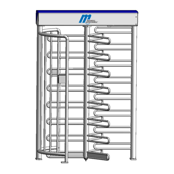
- Page 7 Operating Instructions components Fig. 1 Design of components 1 Lock comb 2 Cage half(s) 3 Upper housing with locking unit 4 Center column 581E,5811_07...
- Page 8 Operating Instructions Fig.2 Entry “left version” Fig. 2.1 Entry “left version” Fig. 2.2 Entry “right version” 581E,5811_07...
- Page 9 Operating Instructions 4. Foundation A level concrete mounting surface is required to secure the turnstile housing. For the dimensions please refer to figure 2. The cables should finish a minimum of 5 meters above the finished concrete surface. NOTE: This foundation is also required in connection with a foundation frame. Conduits for mains supply and data lines should finish 50 mm approx.
-
Page 10: Foundation
Operating Instructions Lay seperate conduits for power supply and data cables, Foundation, smoothed finish 50 mm approx. above foundation to be positioned in water All power supply and in a level and horizontal manner data lines are to be 5 m at least above the empty conduit After mounting empty conduit... - Page 11 Operating Instructions 4.1 Foundation frame The foundation frame is required for turnstiles to be mounted on an uneven surface, for example in case of pavers. A level concrete mounting surface is required for correct mounting of the foundation frame. It should be approx. 150 mm below the finished surface.
- Page 12 Operating Instructions 5. Assembly and installation 5.1 To fit the turnstile (above ground foundation) The turnstile should be positioned in its desired location taking care on which side (right or left) you want to place part 2. (See Fig. 2.1/ 2.2, Fig. 6 ) This is important in case you want to mount access control units at part 2.
- Page 13 Operating Instructions 5.2 Fixing on foundation frame See section 5.1 fixing the foundation. However in this case the turnstile is mounted on the flanges of the foundation frame. Fixing of foundation frame, see section 4.1 Opening of the top cover The hood is fixed with 4 hexagon socket screws.
- Page 14 Operating Instructions To fit the turnstile (above ground foundation) Fixing of the turnstile is done by means of the 8 fixing bolts M8 and plain washer. After final positioning tighten all bolts firmly. Note: 1.Mark the dimensions onto foundation acc. to fig.4 2.
- Page 15 Operating Instructions Fig. 9.1 Locking unit ▼ ▼The home position is reached, when the Countersink is in the Fig. 9.2 position as shown (fit-up aid) ▼ ▼ Home Position bottom view Fig. 9.3 581E,5811_07...
- Page 16 Operating Instructions 5.5 To fit the centre column Fig. 10 Fig. 11 Mount the lower bearing on the foundation and stick the centre column on it. 581E,5811_07...
- Page 17 Operating Instructions Fig. 12 Fix the centre column by means of the delivered screws M16 at the top flange. Make sure the centre is in correct position (centre in locked position). (Locking crest in locked position – see drawing) Center column Cage halves “blocked”...
- Page 18 Operating Instructions EINZELHEIT A Fig. 13.1 1. Fix the center column to the floor bearing using 3 headlees screws. 2. Tighten all 3 headless screws equally, so that the center column can be rotated smoothly in both directions. 3. Secure headless screws using Loctite 241 or similar. 581E,5811_07...
- Page 19 Operating Instructions 5.6 Assembly of roof with drain Assemble the roof as shown on Fig.14. The roof can also be mounted rotated by 180°. Fig.14 581E,5811_07...
-
Page 20: Electrical Connection
Operating Instructions Electrical connections Connection of mains supply should only be performed b y a certified electrian and According to the connecting diagram or after discussion with the supplier. Fig. 16 Fig.15 Connection unit with control unit MSC10 Fig.16 581E,5811_07... - Page 21 Operating Instructions 6.1 Connecting diagram MSC – 10 Fig.17 581E,5811_07...
-
Page 22: Access Control Devices
Operating Instructions 7. Housings / access control units Fig.18 Mounting plate for access control devices Lead the cable from the rear side of the mounting plate to the steel tube and drill the hole. Here, for example Rear side Fig.19 581E,5811_07... -
Page 23: Assembly And Installation
Operating Instructions 8. Commissioning Once the mechanical and electrical installation of the turnstile has been completed, it can be put into service. Check before start-up that all assembly and installation instructions have been followed and the electrical connections have been performed correctly. Warning: 8.1 Operation of the Turnstile Incoming mains supply and... - Page 24 Operating Instructions 9. Control Unit MSC 10 Fix adjusted functions 9.1 Functions of the digital inputs Input 1 = opening – left passage Opening impulse for single left passage. Note: The pulse length for single passage may not exceed 1.5 seconds. If the signal is given for more than 2,5 seconds, the “permanent-free-function”...
- Page 25 Operating Instructions Relay 3 = Display “free passage, left” – clamps X20 – X21 - X 22 With free passage in left direction a permanent signal is given on this output. This output can also be used to block an impulse generator for the right passage direction while left passage is free.
-
Page 26: Adjustable Parameters
DIP 4 / 5 Hardware tests The settings of these dip switches may only be changed after consultation with Magnetic Autocontrol. Originally, both must be set “OFF”. DIP 6 / DIP 7 “Free” / “locked” in case of power failure Depending on the requirements of the application in question it is necessary to assure free passage in one or either direction in case of power failure. - Page 27 Operating Instructions If a passage direction should be free in case of power failure, the respective solenoid has to be built-in in the same line as the mounting plate (Fig.20.1). DIP 6 respectively DIP 7 has to be set “ON” in this case. DIP 6 controls the left solenoid, whereas DIP 7 controls the right solenoid.
-
Page 28: Operation Modes
Operating Instructions If the person begins to pass and the center column is out of its home position, the hold-open-time is set to an unlimited period of time. When the center column is turned over 60°, the hold-open-time will be cleared immediately. - Page 29 Operating Instructions 11.4 Pulsed operation in one -, permanent free in the other direction. If a permanent contact (or wire bridge) is connected to one of the inputs IN1 or IN2, the respective direction is set to free passage. In the opposite direction, the turnstile works in pulsed operation mode. In case permanent contact (>2.5s) is given to an input in pulsed operation mode, stored opening pulses will be cleared for the respective direction.
-
Page 30: Technical Support
Operating Instructions 12. Technical Support Our customer service can be contacted for any technical advice. Information about the responsible contact person can be retrieved by telephone, fax, E-mail or via the Internet at any time, refer to manufacturer's address on Page 2. NOTE! In order to enable fast handling note the data of the type plate such as type, serial number, version etc. - Page 31 Operating Instructions Spare parts 1008,5031 (RAL7042) 1008,5032 (V2A) 1008,5033 (V4A) [Siehe Ersatzteile 5547,5032 2018,0332 2032,5019 (4x) 1031,5285 (230V) 1056,5088 [Siehe Ersatzteile 5547,5012] 3147,5004 1031,5286 (115V) [Siehe Ersatzteile 5547,5013] 3147,5004 2059,50 2059,50 2059,50 2059,50 2059,5101 (vz) 2059,5102 (RAL7042) 2059,5103 (V2A) 2059,5104 (V4A) 2059,5176 (RAL9007) 2059,5042 (vz) 2059,5043 (V4A)
- Page 32 Operating Instructions Spare parts Small parts (without picture) Application field: Art.-Nr. Name 3486,5010 Hexagon screw M16x40 (SS 304) 3498,0018 Washer M16 (SS 304) 3306,0007 Hexagon nut M5 (brass) Countersunk screw with internal hexagon M5x25 3490,5003 (SS 304) 3495,0006 Toothed lock washer M5 (SS 304) 3498,0020 Washer M5 (brass) 3513,0009 Safety ring M5 (SS 304) 3306,0033 Hexagon nut M5 (SS 304)
-
Page 33: Warranty
Operating Instructions 14. Setting of limit switches The limit switches are factory set. In case of a necessary replacement of the limit switches, the settings have to be made according to the drawing. Schalter so einstellen, daß Nocke sicher erkannt wird. Abstand zwischen 0,5 mm und 2,0 mm Switches in such a way adjust, that cam is surely recognized... - Page 34 Operating Instructions 16. Decommissioning ECYCLING! The relevant regional regulations and laws considering disposal of substances, materials and machine parts have to be adhered. Recyclable parts have to be handed over to specialized collection stations! In order to sustain a clean environment it is essential to handle all materials with care and to assure a disposal that causes the smallest possible harm to the environment.
- Page 35 Operating Instructions MAGNETIC Autocontrol GmbH Grienmatt 20 D - 79650 Schopfheim Germany Tel.: +49 7622 695 5 Fax: +49 7622 695 602 eMail: [email protected] www.ac-magnetic.com 581E,5811_07...