
Related Manuals for Ashcroft DURALIFE 1009


Summary of Contents for Ashcroft DURALIFE 1009
- Page 1 PRESSURE GAUGE INSTALLATION, OPERATION AND MAINTENANCE I&M008-10098-5/02 (250-1353H) 1M AMR 5P1/08...
-
Page 3: Table Of Contents
CONTENTS Selection and Application Range ............Page Temperature . - Page 4 Ashcroft Pulsation Dampener ........
-
Page 5: Temperature
(pipe), wall (surface) or panel (flush). media. Use of a dia-phragm seal with the gauge Ashcroft wall or panel mounting kits should be is recommended for process media that (a) are ordered with the gauge. See paragraph 3 corrosive to the process sensing element;... -
Page 6: Ratings
2.3 Steam service – In order to prevent live 2.0 TEMPERATURE steam from entering the Bourdon tube, a 2.1 Ambient Temperature – To ensure long siphon filled with water should be installed life and accuracy, pressure gauges should between the gauge and the process line. preferably be used at an ambient tempera- Siphons can be supplied with ratings up to ture between –20 and +150F (–30 to +65C). -
Page 7: Location
Dry locations away from very high thermal sources (ovens, boilers etc.) are pre- 4.0 OPERATION ferred. If the mechanical vibration level is extreme, the gauge should be remotely locat- 4.1 Frequency of inspection –... -
Page 8: Other Considerations
This policy is prudent in that it encourages ommended that the user maintain in his the user to procure a new gauge, properly tai- parts inventory one complete Ashcroft ® lored by specification, to each application that instrument for every ten (or fraction thereof) arises. - Page 9 (TRUE VALUE minus READING) ÷ feature which permits the user to minimize RANGE. Plotting the individual errors this class of error. Other Ashcroft gauge (Figure 1 on page 10) makes it possible to designs (e.g., 1009 Duralife ) require that the ®...
- Page 10 TYPICAL CALIBRATION CHART INDICATED VALUE (PSI) True Value – Increasing – Increasing – Decreasing – Decreasing – Without RAP With RAP Without RAP With RAP –.4 –.4 +1.0 +1.4 +1.1 +1.2 +1.0 –.4 –1.0 –.8 –.5 ERROR (% OF FULL SCALE) True Value –...
-
Page 11: Calibration - Rotary Movement Gauges
Remove ring, window, gasket and pointer link toward the movement to increase using Ashcroft tool kits 1205T and 1206T. span or away to decrease span. An adjust- ment of 0.004 inch will change the span by 6.3 Positive Pressure Ranges –... - Page 12 ASHCROFT SYSTEM ASSEMBLY Fig. 2 BOURDON TUBE SEGMENT HAIRSPRING PINION LINK ROTARY MOVEMENT BACKPLATE SOCKET TYPE 1082 EXTERNAL ZERO ADJUST FEATURE* Fig. 3 RING INSTRUCTIONS FOR USE: LOOSEN RING LOCKING SCREW “A’’ OBTAIN REQUIRED ADJUSTMENT BY ROTATING KNOB “B’’ CLOCKWISE OR COUNTER-CLOCKWISE.
- Page 13 TYPE 1082 TEST GAUGE CALIBRATION PROCEDURE Fig. 4...
- Page 14 Remove the dial. b. Firmly tap pointer onto pinion, using brass c. Apply 25 inches of Hg vacuum. back-up tool from Ashcroft kit 1205T if gauge has rear blow-out plug. If gauge has d. Lightly press pointer onto pinion carefully top fill hole no back-up is required.
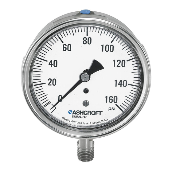
- Page 15 ® 1009 DURALIFE PRESSURE GAUGE CALIBRATION...
-
Page 16: General
Ashcroft 7.0 DIAPHRAGM SEALS diaphragm seal assemblies should only be filled by a seal assembler certified by Ashcroft 7.1 General – A diaphragm seal (isolator) is a Inc. Refer to section 3.3 for a cautionary note... -
Page 17: Throttle Screws & Plugs
Micro-Bean to help pre- fluid. vent plugging. 8.2 Throttle Screws & Plugs – These acces- 8.7 Ashcroft Needle Valves – Type 7001 thru sories provide dampening for the least cost. 7004 steel needle valves provide varying They have the advantage of fitting completely... -
Page 18: Training Videos
9.0 RESOURCES Training Videos 9.1.1 Test gauge calibration 9.1.2 1009 Duralife ® gauge calibration 9.1.3 Duragauge ® gauge calibration 9.1.4 Diaphragm seal filling Pressure Instrument Testing Equipment 9.2.1 Type 1305D Deadweight Tester 9.2.2 Type 1327D Pressure Gauge Comparator 9.2.3 Type 1327CM “Precision” Gauge Comparator Tools &... - Page 20 Ashcroft Inc., 250 East Main Street Stratford, CT 06614-5145 U.S.A. Tel: 203-378-8281 Fax: 203-385-0408 (Domestic) Fax: 203-385-0357 (International) email: [email protected] www.ashcroft.com Visit our web site www.ashcroft.com All sales subject to standard terms and conditions of sale. I&M008-10098-5/02 (250-1353H) 1M AMR 5P1/08...