Table of Contents
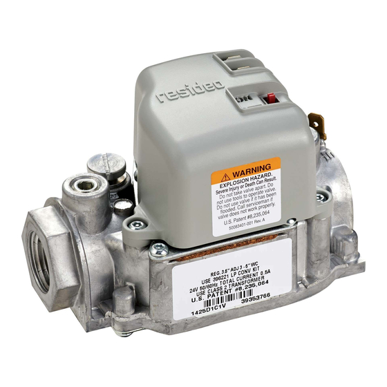
VR8215S,T
Direct Ignition Combination
Gas Controls
APPLICATION
The VR8215S,T Direct Ignition Combination Gas
Controls are used in gas-fired appliances with up to 150
3
ft
/hr capacity at 1 in. wc pressure drop on natural gas.
They have been optimized for direct ignition applications
and include a switch and a pressure regulator.
Size Inlet-
Model
Outlet (in.)
VR8215
1/2 x 1/2
a
Capacity based on 1000 Btu/ft
b
Minimum regulation for LP gas is 30,000 Btuh.
Table 2. Gas Capacity Conversion Factor.
Gas
Specific Gravity
Manufactured
0.60
Mixed
0.70
Propane
1.53
Table 3. Model Number Suffix Letter Designation.
Model Number
Temperature
Suffix Letter
S
-40°F to 175°F
(-40°C to +79°C)
T
Model Number Suffix Letter
S, T
Table 1. Valve Capacity.
AGA Certified
Capacity for Natural
Gas
3
ft
/hr
150
3
, 0.64 sp gr natural gas at 1 in. wc pressure drop.
Multiply Listed
Capacity By
0.516
0.765
1.62
Ambient
Pressure
Range
Regulator Type
Standard
Slow Opening
Table 4. Natural-LP Gas Conversion Kits.
Kit to Convert Natural Gas to LP
396221
• Valve capacities are shown in Table 1.
• Table 2 provides gas capacity conversion factors.
• For suffix letter designation, see Table 3 or 4.
a
AGA Certified Minimum
Regulation for
Natural Gas
3
ft
/hr
b
15
SPECIFICATIONS
Body Pattern: Straight through; see Table 1 for inlet
and outlet size.
Electrical Ratings:
Voltage and Frequency: 24 Vac, 60 Hz.
Current Draw: 0.5A.
Capacity: See Table 1.
Conversion:
Use conversion factors in Table 2 to convert capacities
for other gases.
Regulation Range: See Table 1.
Natural-LP Gas Conversion Kits: See Table 4.
Approvals:
CSA Design Certificate.
INSTALLATION INSTRUCTIONS
AGA Certified Maximum
Regulation for
Natural Gas
3
ft
/hr
200
Kit to Convert LP to Natural Gas
396222
69-2253-01
Table of Contents

Related Manuals for Honeywell VR8215 Series


Summary of Contents for Honeywell VR8215 Series
- Page 1 VR8215S,T Direct Ignition Combination Gas Controls INSTALLATION INSTRUCTIONS APPLICATION The VR8215S,T Direct Ignition Combination Gas • Valve capacities are shown in Table 1. Controls are used in gas-fired appliances with up to 150 • Table 2 provides gas capacity conversion factors. /hr capacity at 1 in.
-
Page 2: Planning The Installation
1. Read these instructions carefully. Failure to follow applications require Honeywell Home and Building them could damage the product or cause a Control Engineering review; contact your Honeywell Sales hazardous condition. Representative for assistance. 2. Check the ratings given in the instructions and on... -
Page 3: Install Bushings To Control
VR8215S,T DIRECT IGNITION COMBINATION GAS CONTROLS Locate the combination gas control where it cannot be CAUTION affected by steam cleaning, high humidity, or dripping water, corrosive chemicals, dust or grease accumulation Equipment Damage Hazard. or excessive heat. Can burn out thermostat or transformer. Applying a jumper across (or shorting) the valve To assure proper operation, follow these guidelines: coil terminals, even temporarily, can burn out the... - Page 4 VR8215S,T DIRECT IGNITION COMBINATION GAS CONTROLS PRESSURE REGULATOR DROP OUTLET ADJUSTMENT (UNDER PIPED PRESSURE CAP SCREW) HORIZONTAL CONTROL SUPPLY INLET PRESSURE RISER CONTROL PIPED 3 IN. INLET OUTLET SUPPLY (76 MM) MINIMUM DROP ON/OFF SWITCH M27670 HORIZONTAL 3 IN. TUBING (76 MM) Fig.
-
Page 5: Startup And Checkout
VR8215S,T DIRECT IGNITION COMBINATION GAS CONTROLS STARTUP AND CHECKOUT (HOT) On-Off Switch The on-off switch settings are as follows: S87B CONTROL MODULE • OFF: Prevents main gas flow through the control. • ON: Permits gas to flow into the control body. Under ALARM, IF USED control of the thermostat and direct ignition module, 24V (GND) -
Page 6: Check And Adjust Gas Input And Burner Ignition
VR8215S,T DIRECT IGNITION COMBINATION GAS CONTROLS Check and Adjust Gas Input Check Safety Lockout and Burner Ignition (Slow-Opening Controls Only) 1. With the system power off and the thermostat set to IMPORTANT call for heat, manually shut off the gas supply. 1. -
Page 7: Maintenance
VR8215S,T DIRECT IGNITION COMBINATION GAS CONTROLS MAINTENANCE CAUTION Equipment Damage Hazard. WARNING Can burn out thermostats or other components in the control string. Fire or Explosion Hazard. Never apply a jumper across (or short) the valve Can cause property damage, severe injury, coil terminals, even temporarily. -
Page 8: Turning Off The Appliance
ON position. Automation and Control Solutions Honeywell International Inc. Honeywell Limited-Honeywell Limitée 1985 Douglas Drive North 35 Dynamic Drive Golden Valley, MN 55422 Toronto, Ontario M1V 4Z9 customer.honeywell.com ® U.S. Registered Trademark © 2008 Honeywell International Inc. 69-2253—01 M.S. 08-08...