
Related Manuals for Fujitsu AB12


Summary of Contents for Fujitsu AB12
- Page 1 Multi Air Conditioning System for Buildings VRF (FREELY SELECTABLE MULTI TYPE SYSTEM) SERVICE MANUAL...
- Page 2 Multi Air Conditioning System for Buildings VRF (FREELY SELECTABLE MULTI TYPE SYSTEM) SERVICE MANUAL – 2 –...
-
Page 3: Table Of Contents
CONTENTS 1. OUTLINE OF SYSTEM MODEL CONSTRUCTION ..................SYSTEM CONSTRUCTION CONDITIONS ............. 1-2-1 REFRIGERANT PIPING ..................1-2-2 SYSTEM WIRING ....................ADDRESS SETTING ....................KINDS OF ADDRESS AND SETTING RANGE ............EXAMPLES OF SYSTEM SETTING ..............2. TEST RUN ADJUSTMENT CHECK ITEMS BEFORE TEST RUN .............. - Page 4 6. INDOOR UNIT OPERATION 6-1 TIMER CONTROL ..................... 59 6-2 FAN CONTROL ......................6-2-1 "AUTO" POSITION ..................... 6-2-2 "LOW" "MED" AND "HIGH" POSITION ..............MASTER CONTROL ....................6-3-1 OPERATION MODE CONTROL ................6-3-2 "AUTO" POSITION ....................6-3-3 "COOL" POSITION ....................6-3-4 "HEAT"...
-
Page 5: Outline Of System
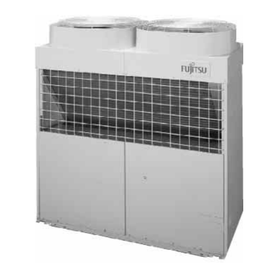
1. OUTLINE OF SYSTEM 1-1 MODEL CONSTRUCTION OUTDOOR UNITS POWER SOURCE TYPE CAPACITY RANGE 3 PHASE 4 LINE COOLING ONLY 415V 50Hz 28.0 kW HEAT PUMP 415V 50Hz 28.0 kW HEAT RECOVERY 415V 50Hz 28.0 kW Compact size 1,300 Serial installation possible INDOOR UNITS 10 types, 39 models ranging from 2.15kW to 17.0kW. - Page 6 RB (REFRIGERANT BRANCH) UNIT Model Max. connectable indoor units UTF-Y90A4A UTF-Y54A1A Above units are required during heat recovery operation. SEPARATION TUBE Type Model Total model code of connectable indoor unit Cooling only UTR-BP54A Less than 60 Heat pump UTR-BP90A More than 61 or more UTR-BP54R Less than 60 Heat recovery...
-
Page 7: System Construction Conditions
1-2 SYSTEM CONSTRUCTION CONDITIONS 1-2-1 REFRIGERANT PIPING COOLING ONLY / HEAT PUMP MODEL 100m (actual pipe length) Difference in height between outdoor unit and indoor units (H1) maximum 50m. (For the outdoor unit stated below:maximum 40m) Difference in height between adjacent indoor units (H2) maximum 15m. e 40m (actual pipe length) 70m (actual pipe length) a+b+c+d+e... - Page 8 PIPE SIZE COOLING ONLY / HEAT PUMP MODEL Pipe size connected to outdoor unit. (unit : mm) Model Gas Pipe Liquid Pipe AO 90 28.58 12.7 Between two adjacent refrigerant branch kits. (unit : mm) Total model code of Gas Pipe Liquid Pipe Separation Kit indoor unit...
- Page 9 HEAT RECOVERY MODEL 100m (actual pipe length) Difference in height between outdoor unit and indoor units (H1) maximum 50m. (For the outdoor unit stated below : maximum 40m) Difference in height between adjacent indoor units (H2) maximum 15m. Difference in height between RB unit and RB unit (H3) 15m or less. Difference in height between Outdoor RB unit and indoor unit (H4) 5m or less.
- Page 10 HEAT RECOVERY MODEL Pipe size connected to outdoor unit. (unit : mm) Model Suction Gas Pipe Discharge Gas Pipe Liquid Pipe AO 90 28.58 19.05 12.7 Between two adjacent refrigerant branch kits. (unit : mm) Total model code of Suction Discharge Liquid Pipe Separation Kit indoor unit...
- Page 11 ADDITIONAL CHARGE Up to a pipe length of 7.5 m, charging with additional refrigerant is not necessary. If the pipe length exceeds 7.5 m, charging with refrigerant is necessary. Charge with additional refrigerant in the amounts shown in the table below. (1) Pipe length Liquid pipe (mm) 12.7...
-
Page 12: System Wiring
1-2-2 SYSTEM WIRING Size Wire type Remarks Maximum H07RN-F or 3 4 wire 50Hz Outdoor unit Minimum equivalent 380-415V Power supply Maximum H07RN-F or 1 2 wire 50Hz cable (mm ) Indoor unit Minimum equivalent 220-240V Shield cord Transmission Maximum 1.25 Non-polar (LONWORKS... -
Page 13: Address Setting
1-3 ADDRESS SETTING This system is needed to set the address for the indoor unit, outdoor unit and remote controller and central remote controller. (1) KINDS OF ADDRESS AND SETTING RANGE SETTING UNIT SETTING TYPE OF SWITCH REMARKS RANGE Outdoor Refrigerant Setting 0 99... - Page 14 Refrigerant circuit address conversion table Outdoor unit Rotary switch (SW 8)- - - Factory setting "0" Rotary switch (SW 9)- - - Factory setting "0" Indoor Unit Rotary switch (SW 7)- - - Factory setting "0" Rotary switch (SW 8)- - - Factory setting "0" In case of multiple refrigerant system,set SW 8 and SW 9 Indoor unit SW7 and SW8 as shown in the table for each refrigerant system.
- Page 15 (2) SETTING EXAMPLE Outdoor Wired remote Central remote unit controller controller Indoor Wireless remote unit controller Outdoor unit Transmission line (Non-polar 2 core) 0 14 0 15 0 2 (Max.16 Numbers) DIP SW1-1 OFF ON DIP SW1-4 OFF ON 63 6 0 DIP SW1-1 DIP SW1-1 OFF ON...
- Page 16 Refrigerant circuit address (Outdoor unit) Refrigerant circuit address (Indoor unit) Refrigerant circuit 1 Refrigerant circuit 2 Outdoor unit PCB (Address setting No.0 Indoor unit PCB (Address setting No.0 Setting by rotary SW8,9 Setting by rotary SW7,8 Indoor unit address 00 0 01 1 02 2 13 0...
- Page 17 Remote controller switch 1 [Master] [Slave] Remote controller unit PCB Setting by DIP SW 1-1 No. indoor unit connection Remote controller PCB Setting by DIP SW 1-2 – 17 –...
- Page 18 Remote controller switch 2 (Remote controller) [Master] [Slave] [Master] [Slave] Remote controller unit PCB Setting by DIP SW 1-4 Central remote controller address Central remote controller (Max.16) Set central remote controller address first,to conduct the initial setting of it. – 18 –...
-
Page 19: Check Items Before Test Run
2. TEST RUN 2-1 CHECK ITEMS BEFORE TEST RUNNING Before test running, check the following items. Note: RB unit ( ) is for the heat recovery type. 2 3 5 6 RB unit 14 15 16 50Hz Outdoor 220 - 240V 10 11 12 unit Indoor... -
Page 20: Outdoor Pc Board
2-2 TEST RUNNING METHOD Supply power to the crankcase heater for 12 hours prior to the start of operation in the winter. The following is the procedure for the test operation. 2-2-1 OUTDOOR PC BOARD If the test operation is to be done for cooling operation, set DIP switch (SW-1-1) to on. If the test operation is to be done for heating, set DIP switch (SW1-2) to on. - Page 21 Error Code Error Code Error contents Error contents No error Blower temperature thermistor error Drain abnormal Model information abnormal Room temperature abnormal Power supply frequency abnormal EEPROM access error Indoor unit fan error EEPROM elimination error Communication error Room temperature thermistor error Node setting error Indoor unit heat exchange thermistor Parallel communication error...
-
Page 22: Test Run Control
2-3 TEST RUN CONTROL 1) When the test run signal is transmitted from the standard wired remote controller, the wireless remote controller and the central remote controller. (1) In the test running status, operated in accordance with the setting of each switch besides the room temperature switch. -
Page 23: Refrigerant Pipe System Diagram
3.REFRIGERANT PIPE SYSTEM DIAGRAM 3-1 COOLING ONLY / HEAT PUMP TYPE – 23 –... -
Page 24: Heat Recovery Type
3-2 HEAT RECOVERY TYPE – 24 –... -
Page 25: Function Of Printed Circuit Board
4. FUNCTION OF PRINTED CIRCUIT BOARD 4-1 PCB LAYOUTS INDOOR UNIT CONTROL CIRCUIT BOARD CN19 CN20 CN21 CN15 CN14 JM1-3 CN11 CN17 CN13 CN10 CN23 CN22 CN25 CN12 CN16 CN24 CN18 CN26 SW10 OUTDOOR UNIT CONTROL CIRCUIT BOARD SW5 SW4SW3 SW2 SW1 SW9SW8 CN33 CN52... -
Page 26: Microprocessor Block Diagram
4-2 MICROPROCESSOR BLOCK DIAGRAM INDOOR UNIT RECTIFICATION DC-DC CONVERTER Power supply FILTER CIRCUIT SMOOTHING 5V,12V,14V CIRCUIT MICROPROCESSOR POWER DETECTION FAN MOTER(CN4) CIRCUIT ACTUATOR DRIVE CIRCUIT DRAIN PUMP(CN5) ROOM THERMISTER(CN19) TEMPERATURE PIPE INLET/IMEDIATE SV(CN6) /OUTLET THERMISTER(CN20) DETECTION CIRCUIT OUTLET THERMISTER(CN21) FAN ROTATION FAN FEEDBACK LOUVER(CN10,CN11) READ CIRCUIT... - Page 27 OUTDOOR UNIT RECTIFICATION DC-DC CONVERTER Power supply FILTER CIRCUIT SMOOTHING 5V,12V,14V CIRCUIT MICROPROCESSOR POWER DETECTION CIRCUIT ST MOTOR EEV (CN29-31) SUCTION/ DRIVE CIRCUIT OUTDOOR/ TEMPERATURE DISCHARGE DETECTION CIRCUIT TEMP. 1-3(CN27) PRESSURE PRESSURE SENSOR(CN32-34) DETECTION CIRCUIT DIP SW(SW1-7) SWITCH ROTARY SW(SW8,9) READ CIRCUIT TEST INPUT TEST(CN35)
-
Page 28: Microprocessor Function List
4-3 MICROPROCESSOR FUNCTION LIST INDOOR UNIT High Large Compact Large Compact Static Static Wall INDOOR UNIT TYPE Universal Ceiling Cassette Duct Pressure Pressure Mounted Cassette Duct Duct 60,000 54,000 45,000 36,000 30,000 24,000(25,000) CAPACITY (BTU/h) 20,000 18,000 14,000 12,000 9,000 7,000 ACIN TH FUSE... - Page 29 OUTDOOR UNIT OUTDOOR UNIT TYPE AOY90TPAMF AC IN FAN.1 FAN.2 BASE HEATER CRANK CASE HEATER S.V.1 S.V.2 S.V.3 CN10 S.V.4 CN11 S.V.5 CN12 S.V.6 CN13 S.V.7 CN14 S.V.8 CN17 4WV.1 CN18 4WV.2 CN19 4WV.3 CN20 4WV.4 CN21 4WV.5 CN22 TERMINATOR CN24 COMP.1 CN25...
-
Page 30: Function And Setting Of Each Switch
4-4 FUNCTION AND SETTING OF EACH SWITCH INDOOR UNIT 1. DIP SWITCH 1 Ceiling height setting. Changeover the fan speed of the indoor fan phase control according to ceiling height (cassette type). Details of rotation is according to DIP SW3 setting. CEILING HEIGHT SETTING 1,2 Standard High ceiling 1... - Page 31 Filter check validity/invalidity. Filter check is set with Dip SW 2-3. FILTER CLEANING FUNCTION SW2-3 Filter check Invalidity Validity 4 Auto restart validity/invalidity. Auto restart is set with Dip SW2-4. But,when a LCD wired remote controller is connected, auto restart is set to "validity" regardless of the indoor unit setting. AUTO RESTART SETTING SW2-4 Auto restart...
- Page 32 INDOOR FAN MOTOR SPEED (CASSETTE) Table No. Models AU54 AU45 AU36 Not used Table No. Models AU30 AU25 Not used AU20 Rotating speed of the indoor fan motor is the same for Cooling/Fan/Heating. Not used (SW3-4). 4. DIP SWITCH 4 Indoor unit model switch.
- Page 33 5. JUMPER Custom code selection of the remote controller. Custom code of the infrared signal is set with jumper lead combinations which are shown below.Once set, other infrared signal is not accepted. REMOTE CONTROLLER CUSTOM CODE SELECTION Custom code Connect Connect Type A (Primary setting) Disconnect...
-
Page 34: Outdoor Unit
OUTDOOR UNIT 1. DIP SWITCH 1 Test run. Test run(forced operation) and normal operation are set with SW1-1.2 on the PCB. The cooling/heating operation mode on the test run is set. Initial setting) TEST RUN SW SW1-2 SW1-1 Test Run Remarks Normal operation (OFF-ON)and (operated continuously... - Page 35 Expansion valve initialize. The pulse of the expansion valve is initialized with SW2-3. Initial setting ) EXPANSION VALVE INITIALIZATION SW Expansion Valve Initialization SW2-3 Remarks Operation Release Operate Forced oil recovery operation. Forced oil recovery operation started with SW2-4. FORCED OIL RECOVERY SW Initial setting ) SW2-4 Forced Oil Recovery...
-
Page 36: Remote Controller
WIRED REMOTE CONTROLLER 1. DIP SWITCH 1 Remote controller address 1 FINAL REMOTE CONTROLLER SWITCH SW1-1 Terminator Indoor unit connection. This is switched according to No. of connected indoor unit. No. INDOOR UNIT CONNECTION SWITCH SW1-2 Number of indoor unit One unit connection Multiple unit connection Remote controller address1,2. - Page 37 SW2-3 setting is forbidden. Maintenance. Used for indication of the refrigerant system, indoor unit address and error history. MAINTENANCE SWITCH SW2-4 Mode Normal mode Maintenance mode SW2-5 setting is forbidden. Battery backup switch. When installing, turn the SW2-6 ON. Ð 12 Ð –...
- Page 38 CENTRAL REMOTE CONTROLLER 1. DIP-SW2 DIP SW2-1 2-2 setting forbidden. DIP SW 2-1 DIP SW 2-2 DIP SW2-3 setting. Filter check sign indication or not when filter check comes from indoor unit. Factory setting) SW2-3 Filter check sign indication Non-Display Display DIP SW2-4 setting.
- Page 39 WIRED REMOTE CONTROLLER TURE OF CONTROLLER Four kinds of timer setup (OFF/ ON1/ ON2/ WEEKLY) are possible. Equipped with weekly timer as standard function. NON STOP CLOCK CENTRAL AUTO AUTO OFFON COOL (2 times Start/Stop per day for a week) TIMER TIMER WEEKLY...
- Page 40 WIRELESS REMOTE CONTROLLER TURE OF CONTROLLER Four kinds of timer setup (ON/OFF/PROGRAM/SLEEP) are possible. Up to 16 indoor units can be simultaneously controlled. Both wired and wireless remote controller can be used jointly. A B C D A B C D FUNCTIONS START/STOP button Pressed to start and stop operation...
- Page 41 CENTRAL REMOTE CONTROLLER MONITOR MEMORY SETTING ERROR TEST CENTRAL CONTROL FILTER TEMP AUTO AUTO COOL ZONE ON OFF CLOCK ADDRESS ADDRESS ENERGY 00 01 02 03 04 05 06 07 08 09 10 11 12 13 14 15 16 17 18 19 HEAT SAVE 20 21 22 23 24 25 26 27 28 29 30 31 32 33 34 35 36 37 38 39...
- Page 42 All ON/OFF button All ON/OFF LED Back button Zone button Change over the zone. Energy save button Starting energy save operation. Fan control button Master control button Anti freeze button Horizontal Air flow direction and swing button Vertical Air flow direction and swing button Temp button Setting of indoor temperature.
-
Page 43: Outdoor Unit Operation Control
5. OUTDOOR UNIT OPERATION CONTROL 5-1 COMPRESSOR OPERATION CONTROL 5-1-1 OPERATION STOP CONDITION Compressor operation condition When cooling requirement capacity or heating requirement capacity from either of the indoor units in the same refrigerant system is input, the compressor operates. But in the following case, the compressor operates in accordance with operation of each mode. -
Page 44: Compressor Recovery Operation
5-1-4 COMPRESSOR RECOVERY OPERATION If compressor 1, 2, or 3 fails, or if two or more compressors fail at the same time, the remaining compressor(s) perform temporary operation to prevent interruption of air conditioning system operation by a failure. When compressor 1, 2, or 3 is judged to be faulty, the system is operated by switching the compressor output pattern (compressors 0 to 7) as shown in the following table. -
Page 45: Heat Exchanger Capacity Control
5-2 HEAT EXCHANGE CAPACITY CONTROL The heat exchanger capacity and four-way valve, solenoid valve, and electronic expansion valve operation states are shown below. 1. Cooling, mainly cooling Solenoid valve Electronic expansion Used heat 4-way valve (4WV) (SV) valve (EEV) exchange (HP) Remarks Pattern 4WV2 4WV3 4WV4... -
Page 46: Outdoor Fan Motor Control
5-3 OUTDOOR FAN MOTOR CONTROL ON /OFF The outdoor fan motor is turned on with the compressor start and turned off with the compressor stop except for the following cases. Also, the operating mode of the outdoor unit is changed, fan speed at each operating mode after changing is controlled. - Page 47 Fan Speed Switching (a) Fan Control of cooling mode and cooling principal mode. The fan motor is operated at fan speed shown in Table 1 from the outside temperature. Table 1 Fan speed switching from the outside temperature OUTSIDE TEMPERATURE USUAL NIGHT OPERATING MODE >...
-
Page 48: Expansion Valve 1/2 Control
5-4 EXPANSION VALVE 1/2 CONTROL The expansion valves have the following four states: CONTROL STOP : Power is not yet supplied to the outdoor unit so the expansion valve does not operate. STAND BY : Power is supplied to the outdoor unit and the expansion valve is initialized, but automatic control of the expansion valve has not been performed. -
Page 49: Four-Way Valve 1 Control
5-5 FOUR-WAY VALVE 1 CONTROL Four-way valve 1 (4WV1) operates for "Cooling/heating selection" type only. 1. 4-way valve delayed switching When the outdoor operation mode is Stop, 4-way valve 1 maintains its state and turns off 2 minutes 35 seconds later. However, when the outdoor unit operation mode is switched from "... -
Page 50: Circulating Save Amount Control
5-6 CIRCULATING SAVE AMOUNT CONTROL * Expansion Valve Control As there is the difference between compressor’s actual capacity and compressor’s requirement capacity practically, capacity by the difference is bypassed as a circulating save amount. ( Compressor’s actual capacity – Compressor’s requirement capacity ) Start condition In case of other than that the compressor 1 (2 HP compressor) is operated by only one compressor. -
Page 51: Solenoid Valve 2 Control
5-7 SOLENOID VALVE 2 CONTROL The outdoor unit operates at the time of the same capacity operation. When the difference between compressor's actual capacity fixed by a compressor and compressor's requirement capacity obtained by cooling (or heating) requirement capacity from the indoor unit is saved (bypassed) as a circulating save amount, the electromagnetic valve 2 is controlled. -
Page 52: Four-Way Valve 5 Control
5-8 FOUR-WAY VALVE 5 CONTROL System type switching The 4-way valve 5 is used properly depending on the model as shown below. HEAT RECOVERY HEAT PUMP COOLING ONLY TYPE TYPE TYPE 4-WAY VALVE 5 : Used (ON/OFF operation under condition) : Not used (always OFF) 4-Way valve 5 setting by the operating mode (a) 4-Way valve 5 setting by the operating mode... -
Page 53: Defrosting Control
5-9 DEFROSTING CONTROL 1. Defrosting start conditions 1) Defrosting start conditions When the forced defrosting SW was operated, or all of the following conditions are satisfied, defrosting starts. Operation mode is "Heating" and the integrated operating time in the state in which any of the compressors is operating has reached 40 minutes or longer When the operating time of any compressor is the specified time (A minutes) or longer. -
Page 54: Oil Return Control
5-10 OIL RETURN CONTROL There are two oil return controls, one is the individual oil return and the other one is centralized oil return. When each solenoid valve is turned ON, the oil return is performed COMP.1 Oil level status is defined in accordance with performance SEPARATER of the oil level sensor. -
Page 55: Oil Recovery Control
5-11 OIL RECOVERY CONTROL When any the following conditions is satisfied, the indoor fan stops and " Oil recovery operation " starts. (1) One or more compressor are operating. (2) The integrated operating time in the " 1 or more compressors operating state " has exceeded 4-6 hours. (3) Defrosting is not performed. -
Page 56: Protection Function
5-12 PROTECTION FUNCTIONS 1. Central discharge temperature protection 1) When the discharge temperature of any compressor reaches 110 C or higher, solenoid valve 1 (SV1) is turned on and bypass is performed. SV1 is turned off and central discharge temperature protection operation is ended by any of the following conditions: (1) Discharge temperature of all compressors reaches 95 C or lower (2) Oil recovery operation starts... -
Page 57: Pump Down Control
5-13 PUMP DOWN CONTROL (1) If the following condition was satisfied, the pump down control starts. When the operation mode is stopped and pump down DIP-SW turns OFF (2) Pump down flow-chart. OUTDOOR UNIT Operation mode " STOP " DIP-SW " ON " +30sec Compressor 1 3 "... - Page 58 INDOOR UNIT When the indoor unit receives the “Pump down signal” from the outdoor unit, the indoor unit is performed following operation. Starts receiving pump down signal Electric expansion valve : 1900 pulse RB unit Discharge valve : ON Suction valve : ON Bypass valve : ON Indoor fan motor : Hi Finish receiving...
-
Page 59: Indoor Unit Operation
6. INDOOR UNIT OPERATION CONTROL 6-1 TIMER CONTROL There are three timer modes: "OFF TIMER", "ON TIMER" and Remote control button selected "WEEKLY TIMER" . (1) Set the clock time when the unit is in the stop mode (only the CLOCK current time will be shown on the remote control unit display). - Page 60 Setting Up the Weekly Timer Operation Press the START/STOP button to stop the air conditioner, and then proceed as follows. 1. Press the TIMER MODE button so that "WEEKLY" COOL appears on the display. TIMER WEEKLY The display now shows the current day (by DAY CODE), the first ON and OFF times for the day (the "WEEKLY 1"...
- Page 61 9. Press the SET TEMP./DAY button to select another day for setup. The repeat steps 4 to 8 above to set the ON and OFF times for that day. CLOCK 10. When you have finished setting all of the times, hold down the SET button for 3 seconds.
- Page 62 About the DAY OFF Use the DAY OFF setting to switch off timed operation for a selected day in the coming week. This is a temporary, one-time setting. The DAY OFF setting is automatically cleared as soon as the specified day passes. Using the DAY OFF Setting Press the START/STOP button to stop the air conditioner, and then proceed as follows.
- Page 63 Cancelling Selected Time Settings AUTO AUTO Press the START/STOP button to stop the air conditioner, and TIMER TIMER WEEKLY WEEKLY then proceed as follows. DEFROST TEST TIMER SET TIME TEMP./DAY 1. Carry out steps 1 to 3 of the "Setting Up the Weekly Timer MODE CONTROL TIMER...
-
Page 64: Fan Control
6.2 FAN CONTROL Fan speed zone 6-2-1 "AUTO" POSITION 3 C or more Hi zone 1) COOLING OPERATION 2 C or more Less than 3 C Air flow mode is set automatically in accordance with the Less than 2 C 2 C or more Med zone condition "(Room temp. -
Page 65: Master Control
6-3 MASTER CONTROL 6-3-1 OPERATION MODE CONTROL Each operation mode is controlled as below. (1) Stop motion Indoor fan motor : OFF RB unit discharge valve : OFF RB unit suction valve : OFF RB unit by-pass valve : OFF Electric expansion valve : Stop pulse Drain pump... - Page 66 < > After automatic operation decided Cooling operation Heating operation "Shunt controller" : "Indoor fan motor" : OFF Discharge valve OFF "Shunt controller" : Suction valve ON Suction valve OFF Bypass valve OFF Bypass valve OFF "Electronic expansion Valve" : Rated electronic expansion valve pulse 90 mask...
- Page 67 Note 1. Monitoring 1 performs the following for 60 seconds and detects the " Room temperature " from the point that " Operation started ". " Indoor unit fan motor " : S-L " Shunt controller discharge valve " : OFF "...
- Page 68 AUTO CHANGEOVER operation (COOLING ONLY TYPE ) (1) When starting the operation at “AUTO” or Operation flow chart when switched to “AUTO” from other modes, if the room temperature is higher START than the set temperature +2 C (Room temp. Set temp.
-
Page 69: Cool" Position
6-3-3 “COOL” POSITION (1) When using the cooling mode, set the temperature to a value lower than the current room temperature. (2) If it is set higher than the current room temperature the unit will not enter the cooling mode and only the fan will oper- ate. -
Page 70: Fan" Position
6-3-5 “FAN” POSITION (1) In this position, the fan operates alone to circulate air. The room temperature will not be changed. (2) Operates at the air flow set in the FAN CONTROL mode. (3) When only the “FAN” mode is being used, setting to “AUTO” is equivalent to set it at “MED”. –... -
Page 71: Louver Control
6-4 LOUVER CONTROL (1) ADJUSTING THE DIRECTION OF AIR CIRCULATION Instructions relating to heating (∗) are applicable only to "HEAT & COOL MODEL" (Reverse Cycle). Begin air conditioner operation before performing this procedure. SET TIME TIMER TEMP./DAY MODE CONTROL MASTER CONTROL Vertical Air Direction Adjustment CLOCK ADJUST... - Page 72 Use the air direction adjustments within the ranges shown above. The vertical airflow direction is set automatically as shown, in accordance with the type of operation selected. During Cooling mode : Horizontal flow ∗ During Heating mode : Downward flow During AUTO mode operation, for the first minute after beginning operation, airflow will be horizontal ;...
- Page 73 Press the VERTICAL SWING button for more than two seconds. The remote controller's VERTICAL SWING lamp (orange) **and TIMER SET TIME TEMP./DAY MODE CONTROL MASTER indoor unit's SWING indicator lamp (VERTICAL SWING) CONTROL (orange) will light up. CLOCK ADJUST In this mode, the UP/DOWN air direction flaps will swing automat- ZONE ENERGY SAVE START/STOP...
-
Page 74: Electronic Expansion Valve Control
6-5 ELECTRONIC EXPANSION VALVE CONTROL After the power is turned on, the following operation is controlled automatically to control the most suitable refrigerant charge according to the operation mode and operation conditions of each unit. Electronic expansion valve control process. The electronic expansion valve adjusts the opening by selecting the number of pulses from the rated capacity,operation mode ( cool / heat ) and set temperature of each indoor unit. - Page 75 7. WIRING DIAGRAMS 7-1 UNIVERSAL FLOOR / CEILING TYPE MODELS : AB12, AB14, AB18, AB24 For Heat Recovery only UNIT – 75 –...
- Page 76 7-2 LARGE CEILING TYPE MODELS : AB30, AB36, AB45, AB54 For Heat Recovery only UNIT – 76 –...
- Page 77 7-3 COMPACT DUCT TYPE MODELS : AR7, AR9, AR12, AR14,AR18 For Heat Recovery only UNIT – 77 –...
- Page 78 7-4 LOW STATIC PRESSURE DUCT TYPE MODELS : AR25, AR30, AR36, AR45 For Heat Recovery only UNIT – 78 –...
- Page 79 7-5 HIGH STATIC PRESSURE DUCT TYPE MODELS : AR36H, AR45H, AR60H For Heat Recovery only UNIT – 79 –...
- Page 80 7-6 COMPACT CASSETTE TYPE MODELS : AU7, AU9, AU12,AU14,AU18 For Heat Recovery only UNIT – 80 –...
- Page 81 7-7 NEW CASSETTE TYPE MODELS : AU20, AU25, AU30,AU36,AU45,AU54 For Heat Recovery only UNIT – 81 –...
- Page 82 7-8 WALL MOUNTED TYPE MODELS : AS14 , 20 , 24 , 30 – 82 –...
-
Page 83: Outdoor Unit
7-9 OUTDOOR UNIT MODEL : AOY90 – 83 –... -
Page 84: Troubleshooting
8. TROUBLESHOOTING 8-1 INDOOR UNIT SWING LAMP (Orange) TIMER LAMP (Green) OPERATION LAMP (Red) MANUAL SWING TIMEROPERATION AUTO Operation can be checked by lighting and flashing of the grille display section OPERATION and TIMER lamps. perform judgment in accordance with the following. Test running When the air conditioner is run by pressing the remote controller test run button, the OPERATION and TIMER lamps flash slowly at the same time. -
Page 85: Abnormal Operation Display
8-1-2 ABNORMAL OPERATION DISPLAY O p e r a t i o n L a m p T i m e r L a m p S w i n g L a m p Error contents 0.1 sec. ON / OFF 0.1 sec. - Page 86 Table 11 Error contents Error display Error display Error contents 0.1 sec 5 sec Drain error 0.1 sec 0.5 sec 0.5 sec Four quick (Float switch ON/OFF OPERATION OPERATION flashes repeated operation) LAMP LAMP repeated 0.1 sec The float Model data 0.1 sec switch oper- 0.1 sec...
- Page 87 Error display Error contents 0.1 sec 0.1 sec OPERATION ON/OFF LAMP repeated 0.1 sec 0.5 sec 0.5 sec Three quick Outdoor unit TIMER flashes error LAMP repeated Three quick SWING flashes LAMP repeated 5 sec – 87 –...
-
Page 88: Outdoor Unit
8-2 OUTDOOR UNIT 8-2-1 NORMAL OPERATING DISPLAY LED 1 LED 2 LED 3 LED 4 LED 5 LED 6 Display Type Cooling operation Heating operation Cooling main operation Heating main operation Same performance operation Compressor output STEP1 Compressor output STEP2 Compressor output STEP3 Compressor output STEP4 Compressor output STEP5... -
Page 89: Abnormal Operation Display
8-2-2 ABNORMAL OPERATION DISPLAY Display type LED 1 LED 2 LED 3 LED 4 LED 5 LED 6 Compressor1 error Compressor2 error Compressor3 error Discharge temprature1 error Discharge temprature2 error Discharge temprature3 error High-pressure error Low-pressure error Pump down error Discharge temperature thermistor1 error Discharge temperature thermistor2 error Discharge temperature thermistor3 error... -
Page 90: Remote Control Unit
8-3 REMOTE CONTROL UNIT Error Code NON STOP CLOCK COOL SET TIME SET TIME TIMER TEMP./DAY TIMER TEMP./DAY MODE CONTROL MODE CONTROL MASTER MASTER CONTROL CONTROL CLOCK ADJUST CLOCK ADJUST START/STOP START/STOP ZONE ENERGY SAVE ZONE ENERGY SAVE DAY OFF DAY OFF When EE : EE blinks at the current time display, there Error Code... -
Page 91: Error Code & Troubleshooting
8-4 ERROR CODE & TROUBLESHOOTING INDOOR UNIT TROUBLESHOOTING ERROR ERROR CONTENTS ERROR CAUSE REMEDY CODE No errors Model data error 1. Generation condition Model information not Replace indoor unit control PC board. Error in model information memorized or erased for some memorized in EEPROM when reason. - Page 92 ERROR ERROR CONTENTS ERROR CAUSE REMEDY CODE Replace indoor unit control PC board. EEPROM 1. Generation condition. Model information not deletion error Error in model information memorized, or erased for some memorized at EEPROM after reason. indoor unit started. 2. Corresponding operation. 1) Relevant indoor unit stopped 2) Error display to indoor unit LED.
- Page 93 ERROR ERROR CONTENTS ERROR CAUSE REMEDY CODE 1. Connector connection faulty. 1. Check for loose or dislodged blower Blower tempe- 1. Generation condition temperature thermistor connector. rature thermistor Thermistor short or open error detected. 2. Blower temperature thermistor 2. Check resistance of blower temperature 2.
- Page 94 ERROR ERROR CONTENTS ERROR CAUSE REMEDY CODE Transmission 1. Generation condition. 1. Effect of extraneous noise. 1. When power turned OFF, then turned error Communication between back ON: indoor unit and outdoor unit (1) If error not generated again, PC board exceeds certain time.
- Page 95 ERROR ERROR CONTENTS ERROR CAUSE REMEDY CODE Parallel commu- 1. Generation condition. 1. Effect of extraneous noise. 1. When power turned off, then turned nication error Communication between back on: indoor unit control PC board 1) If error not generated again, PC board and indoor unit is normal.
-
Page 96: Outdoor Unit Troubleshooting
OUTDOOR UNIT TROUBLESHOOTING ERROR ERROR CONTENTS ERROR CAUSE REMEDY CODE No errors 1. Generation condition. Model information not Replace outdoor unit control PC board. Model When power turned on, there memorized, or erased for some data error was an error in model reason. - Page 97 ERROR ERROR CONTENTS ERROR CAUSE REMEDY CODE 1. Generation condition. EEPROM cannot be accessed 1. Remove noise sources near outdoor EEPROM After outdoor unit started, because of disturbance, element unit. access error EEPROM cannot be error, etc. 2. Replace outdoor unit control PC board. accessed because of disturbance or element error.
- Page 98 ERROR ERROR CONTENTS ERROR CAUSE REMEDY CODE 1. Generation condition. Compressor 2 1. Discharge temperature sensor 1. Check for loose or dislodged discharge Thirty minutes after error faulty. temperature sensor TH sensor wiring compressor 2 started, and check sensor resistance. If discharge temperature 2 abnormal, replace sensor.
- Page 99 ERROR ERROR CONTENTS ERROR CAUSE REMEDY CODE 1. Generation condition. Discharge 1. Connector contact faulty. 1. Check for loose or dislodged discharge Thermistor short or open temperature temperature thermistor TH connector. detected. thermistor 1 2. Discharge temperature 2. Check discharge temperature 2.
- Page 100 ERROR ERROR CONTENTS ERROR CAUSE REMEDY CODE 1. Generation condition. 1. Connector contact faulty. Outdoor 1. Check for loose or dislodged outdoor Thermistor short or open thermistor TH connector. thermistor error detected. 2. Outdoor thermistor TH 2. Check outdoor thermistor TH 2.
- Page 101 ERROR ERROR CONTENTS ERROR CAUSE REMEDY CODE 1. Generation condition. Discharge pressure sensor P Discharge Replace discharge pressure sensor P 1) Voltage output from output faulty. pressure sensor remains under 0.8V for 3 error minutes or longer. However, Liquid line pressure sensor P Replace liquid line pressure sensor P Liquid line not detected for 3 minutes...
- Page 102 ERROR ERROR REMEDY CONTENTS ERROR CAUSE CODE 1. Generation condition. 1. Affect of extraneous noise. 1. When power turned off, then turned on Communication Communication from indoor error again: units cuts off certain time. 1) If error not generated again, PC board 2.
- Page 103 ERROR ERROR REMEDY CONTENTS ERROR CAUSE CODE 1. Generation condition. 1. Gas leak or refrigerant level 1. Check for leak and check additional Discharge Discharge temperature 1 low. temperature 1 refrigerant amount and recharge remains 130 C or greater for suitable refrigerant.
- Page 104 ERROR ERROR REMEDY CONTENTS ERROR CAUSE CODE 1. Generation condition. 1. Gas leak or refrigerant level 1. Check for leak and check additional Discharge Discharge temperature 2 low. temperature 2 refrigerant amount and recharge remains 130 C or greater for suitable refrigerant.
- Page 105 ERROR ERROR REMEDY CONTENTS ERROR CAUSE CODE 1. Generation condition. 1. Gas leak or refrigerant level 1. Check for leak and check additional Discharge Discharge temperature 3 low. temperature 3 refrigerant amount and recharge remains 130 C or greater for suitable refrigerant.
- Page 106 ERROR ERROR CONTENTS ERROR CAUSE REMEDY CODE 1. Generation condition. 1. Ball valve not open 1. Open ball valve fully. High-pressure When any of following completely. error conditions satisfied: 1) High-pressure protection 2. Outdoor unit short cycle. 2. Check required installation dimensions. stops compressor 2 times or more in 40 minutes.
- Page 107 ERROR ERROR CONTENTS ERROR CAUSE REMEDY CODE 1. Generation condition. 1. Ball valve not open 1. Open ball valve fully. Low pressure When any of following completely. error conditions satisfied: 1) Low-pressure protection 2. Pressure SW faulty. 2. Check pressure using pressure gauge. stops compressor 2 or more If pressure SW faulty, replace SW.
- Page 108 ERROR ERROR REMEDY CONTENTS ERROR CAUSE CODE 1. Generation condition. Pump down SW remains ON. Pump down Switch outdoor unit control PC board Six minutes have elapsed error pump down DIP SW1-3 from ON to OFF. since pump down performed, or discharge pressure sensor PH is 3MPa or higher.
-
Page 109: Central Remote Controller Troubleshooting
CENTRAL REMOTE CONTROLLER TROUBLESHOOTING ERROR ERROR CONTENTS ERROR CAUSE REMEDY CODE No errors PC board error 1, After ACL key pressed, or power 1, Generation condition 1, Effect of extraneous noise. ( Control panel ) Error generated at control turned on again : 1) If error not generated again, PC board panel PC board and central is normal.Therefore, remove noise... - Page 110 ERROR ERROR CONTENTS ERROR CAUSE REMEDY CODE Memory error 3, Reset conditions. 1) When error generated in normal state Key SW42 on control panel PC board pressed and memory cleared. 2) When error generated in initial setting menu mode. Set key pressed and memory cleared.
- Page 111 ERROR ERROR ERROR CAUSE REMEDY CONTENTS CODE 1, Effect of extraneous noise. Connection 1, Generation condition. 1-1, Check error continuity. error Communication between 1) If error reset automatically, PC board transmission adapter and is normal. Therefore, remove noise control panel not sources near central remote controller.
- Page 112 ERROR ERROR CONTENTS ERROR CAUSE REMEDY CODE Initial setting 1, Generation condition. 1, Effect of extraneous noise. 1, Repeat initialization.After initializa- error Initialization not performed tion: normally. 1) If error not generated again, PC- 2, Corresponding operation board is normal. Error display.
- Page 113 ERROR ERROR CONTENTS ERROR CAUSE REMEDY CODE Transmission 3, Reset condition 4, Transmission adapter com- Check insertion of communication error munication PC board or indoor adapter communication PC board For 2-1), communication with indoor unit restored. and indoor unit communication PC unit communication PC board insertion faulty.
-
Page 114: Troubleshooting (No Error Code)
Troubleshooting (No error code) 8-4-1 How to read the tables 1.Select the relevant item errors 1 to 5 below,and decide the table to be used. 2.Deduce "Cause" from "LED display" and "Symptom that can occur other than title". 3.Check if the deduced "Cause" is correct by means of "Check" and "Remarks". When there is no error code display at the indoor unit ,outdoor unit or centralized remote controller, but there is one of the following operation errors,check the cause in the following order: 1.Indoor fan does not operate normally... -
Page 115: Others 1
LED display Indoor Outdoor Remote Symptom that Check method unit unit controller Remarks Cause can occur other (Error state check method) PCB LED Body than title 1 to 6 Normal Normal Filter Filter clogged Check if the filter is dirty. When the indoor unit fan motor display display... - Page 116 2. System does not cool or heat LED display Indoor Outdoor Remote Symptom that Check method Remarks unit unit controller Cause can occur other (Error state check method) PCB LED Body than title 1 to 6 Check each outdoor unit power Error No display Error...
- Page 117 LED display Indoor Outdoor Remote Symptom that Check method unit unit controller Remarks can occur other Cause (Error state check method) PCB LED Body than title 1 to 6 Indoor unit electronic expansion When the relevant indoor unit Coil resistance (red-white, red- Normal Normal Normal...
- Page 118 LED display Symptom that Indoor Outdoor Remote Check method unit unit controller can occur other Cause Remarks (Error state check method) than title PCB LED Body 1 to 6 Indoor unit Normal Normal Normal Installed piping not suitable. Check the indoor unit capacity When the diameter is large, makes an a refrigerant rushing sound is...
- Page 119 LED display Indoor Outdoor Remote Symptom that Check method unit unit controller Cause can occur other Remarks (Error state check method) than title Body PCB LED 1 to 6 Error display Outdoor thermistor faulty. Check by measuring the Error display Error display Refer to the service manual (Thermistor...
- Page 120 LED display Indoor Outdoor Remote Symptom that Check method unit unit controller Cause can occur other Remarks (Error state check method) Body PCB LED than title 1 to 6 Controlling Normal Defrosting operation in progress Outdoor unit heat exchanger Controlling Operation display LED display display...
- Page 121 3. Abnormal sound is heard from the indoor unit. LED display Indoor Outdoor Remote Symptom that Check method unit unit controller Cause Remarks can occur other (Error state check method) than title Body PCB LED 1 to 6 Normal Normal Normal When heating operation starts, Coil resistance : 1200~1500...
- Page 122 LED display Check method Indoor Outdoor Remote Symptom that Cause Remarks unit unit controller (Error state check method) can occur other Body PCB LED than title 1 to 6 Normal System does When the ball valve is fully open, Normal Normal Ball valve opening faulty.
- Page 123 5. Others LED display Indoor Outdoor Remote Check method Symptom that unit unit controller Cause Remarks (Error state check method) can occur other Body PCB LED than title 1 to 6 Normal Normal Normal Indoor unit electronic expansion When the indoor unit power is display display display...
-
Page 124: Others
8-5 OTHERS 8-5-1 CHARACTERISTICS OF THERMISTOR Thermistor resistance values1) Room temperature thermistor Room tempera- 12.5 17.5 22.5 27.5 ture ( C) Resistance value 33.6 29.5 25.9 22.8 20.2 17.9 15.8 14.1 12.5 11.2 10.0 (k ) Room tempera- 32.5 37.5... -
Page 125
Thermistor resistance values
1) Outdoor heat exchanger temperature thermistor Pipe tempera- -7.5 -5.0 -2.5 ture ( C) Resistance value 384.8 182.8 92.3 49.2 27.5 24.0 20.9 18.3 16.1 14.1 12.4 11.0 (k ) Pipe tempera- 12.5 15.0 17.5 22.5 25.0... -
Page 126: Pressure Sensor
8-5-2 PRESSURE SENSOR 1) Characteristics of pressure sensor 1.75 Pressure 2) Check point of replacing pressure sensor Lead wire Pressure sensor Printed circuit board When installing the pressure sensor, connect a lead wire to the PCB ( ), thereafter connect the other end of a lead wire to the pressure sensor ( ). - Page 127 8-5-6 OUTDOOR HEAT EXCHANGER CAPACITY AND THE STATE OF 4-WAY VALVE, ELECTROMAGNETIC VALVE, AND ELECTORONIC EXPANSION VALVE 1.Cooling operation Electromagnetic valve in Electronic expansion 4-way valve in the energized mode Heat exchange valve opening the energized mode capacity(HP) 4WV2 4WV3 4WV4 EEV1 EEV2...
- Page 128 O U T D O O R U N I T I N T E R N A L L A Y O U T F A N 2 F A N 1 ...
-
Page 129: In Use Of The New Refrigerant R407C
9. IN USE OF THE NEW REFRIGERANT R407C 9-1 What is CFC/HCFC/HFC ? C CI C CI (HC : Methane) (CFC-12) (HCFC-22) (HFC-407C) : Chloro-Fluoro-Carbon = high ODP(ozone depletion potential) chemical compound containing chlorine (ODP: 0.6 - 1.0) HCFC : Hydro-Chloro-Fluoro-Carbon (R22) = Iow ODP chemical compound containing chlorine and hydrogen (ODP:1/10 - 1150 of CFC) : Hydro-Fluoro-Carbon (R407C) = zero ODP new chemical compound in which is not containing chlorine (ODP: 0) - Page 130 9-3 Difference from conventional model (R22) and precautions • Use new synthetic oils such as ester because HFC series refrigerant has less solubility with mineral oils conventionally used for R22. • As these new synthetic oils are easily influenced by moisture and dusts, they must be treated morecare- fully than the conventional lubricating oils.
- Page 131 BALL VALVE • Review material O-ring, valve core seal for securing suitability with oil. CAUTION Check if the valve is suitable for the refrigerant (model) when replacing. DRYER • Change desiccant (XH-6 XH-10) Volume of desiccant is increased. CAUTION Complete welding within one hour after the package of dryer is opened. PRESSURE SWITCH •...
- Page 132 9-4 Tools Gauge manifold ..... TOOLS AND EQUIPMENT (R407C) (Fig.4-1) Pressure gauge changed. Charge hose ..... . . (Fig.4-2) Changed to HFC resistant material.
- Page 133 Always use a vacuum pump to purge the air. When replacing parts, be sure to check if the parts are In the case of Fujitsu General's new refrigerant suitable for the refrigerant(model). model, refrigerant for purging the air is not charged in For most refrigeration cycle parts which have same the outdoor unit at the factory.
-
Page 134: Disassembly Illustration
10. DISASSEMBLY ILLUSTRATION Models : AOY90TPAMF – 134 –... - Page 135 Models : AOY90TPAMF – 135 –...
- Page 136 Models : AOY90TPAMF 163-2/ 181-4 163-2/ 181-4 163-2/ 181-4 – 136 –...
- Page 137 Models : AOY90TPAMF – 137 –...
- Page 138 212/ – 138 –...
- Page 139 212/ – 139 –...
- Page 140 Models : ABY12TFAMF ABY14TFAMF ABY18TFAMF ABY24TFAMF 365-2 653-2 365-1 870-1 365-2 870-1 653-2 365-1 – 140 –...
- Page 141 Models : ABY12TFAMF ABY14TFAMF ABY18TFAMF ABY24TFAMF 870-2 196-1 574-2 588-2 574-1 588-1 – 141 –...
- Page 142 Models : ABY12TFAMF ABY14TFAMF ABY18TFAMF ABY24TFAMF 653-1 – 142 –...
- Page 143 Models : ABY12TFAMF ABY14TFAMF ABY18TFAMF ABY24TFAMF – 143 –...
- Page 144 Models : ABY12TFAMF ABY14TFAMF ABY18TFAMF ABY24TFAMF ABY18TFAMF 234-1 OPTIONAL PARTS ABY24TFAMF OPTIONAL PARTS – 144 –...
- Page 145 Models : ABY12TFAMF ABY14TFAMF ABY18TFAMF ABY24TFAMF 824-3 731-2 36-2 – 145 –...
- Page 146 Models : ABY12TFAMF ABY14TFAMF ABY18TFAMF ABY24TFAMF – 146 –...
- Page 147 Models : ABY12TFAMF ABY14TFAMF ABY18TFAMF ABY24TFAMF 365-2 653-2 365-1 870-1 365-2 870-1 653-2 365-1 – 140 –...
- Page 148 Models : ABY12TFAMF ABY14TFAMF ABY18TFAMF ABY24TFAMF 870-2 196-1 574-2 588-2 574-1 588-1 – 141 –...
- Page 149 Models : ABY12TFAMF ABY14TFAMF ABY18TFAMF ABY24TFAMF 653-1 – 142 –...
- Page 150 Models : ABY12TFAMF ABY14TFAMF ABY18TFAMF ABY24TFAMF – 143 –...
- Page 151 Models : ABY12TFAMF ABY14TFAMF ABY18TFAMF ABY24TFAMF ABY18TFAMF 234-1 OPTIONAL PARTS ABY24TFAMF OPTIONAL PARTS – 144 –...
- Page 152 Models : ABY12TFAMF ABY14TFAMF ABY18TFAMF ABY24TFAMF 824-3 731-2 36-2 – 145 –...
- Page 153 Models : ABY12TFAMF ABY14TFAMF ABY18TFAMF ABY24TFAMF – 146 –...
- Page 154 Models : ABY30TFAMF ABY36TFAMF ABY45TFAMF ABY54TFAMF – 147 –...
- Page 155 Models : ABY30TFAMF ABY36TFAMF ABY45TFAMF ABY54TFAMF – 148 –...
- Page 156 Models : ABY30TFAMF ABY36TFAMF ABY45TFAMF ABY54TFAMF – 149 –...
- Page 157 Models : ABY30TFAMF ABY36TFAMF ABY45TFAMF ABY54TFAMF – 150 –...
- Page 158 Models : ABY30TFAMF ABY36TFAMF ABY45TFAMF ABY54TFAMF 253-5 253-2 253-4 253-6 253-7 236-1 253-2 253-1 185-1 982-1 815-1 381-4 982-2 – 151 –...
- Page 159 Models : AUY 7TFAMF AUY 9TFAMF AUY12TFAMF AUY14TFAMF AUY18TFAMF 117-3 967-2 163-21/184-1 476-3 476-2 476-1 – 152 –...
- Page 160 Model : AUY 7 TFAMF AUY 9 TFAMF AUY 12 TFAMF AUY 14 TFAMF AUY 18 TFAMF 824-3 989-2 989-1 – 153 –...
- Page 161 Models : AUY 7TFAMF AUY 9TFAMF AUY12TFAMF AUY14TFAMF AUY18TFAMF 876-2 690 692 711-2 711-1 – 154 –...
- Page 162 Models : AUY20TFAMF AUY25TFAMF AUY30TFAMF AUY36TFAMF AUY45TFAMF AUY54TFAMF – 155 –...
- Page 163 Models : AUY20TFAMF AUY25TFAMF AUY30TFAMF AUY36TFAMF AUY45TFAMF AUY54TFAMF 163-2/184-1 652-1 – 156 –...
- Page 164 Models : AUY25TLAMA, AUY30TLAMA AUY36TLAMA, AUY45TLAMA – 157 –...
- Page 165 Models : ARY25TLAMA, ARY30TLAMA ARY36TLAMA, ARY45TLAMA – 158 –...
- Page 166 Models : ARY25TLAMA, ARY30TLAMA ARY36TLAMA, ARY45TLAMA – 159 –...
- Page 167 Models : ARY25TFAMF ARY30TFAMF ARY36TFAMF ARY45TFAMF – 160 –...
- Page 168 Model ARY7TFAMF ARY9TFAMF 163-2/184-1 196-2 588-1 588-2 381-4 – 161 –...
- Page 169 Model ARY7TFAMF ARY9TFAMF - 162 -...
- Page 170 Model ARY7TFAMF ARY9TFAMF – 163 –...
- Page 171 Model ARY12TFAMF ARY14TFAMF ARY18TFAMF 163-2/184-1 – 164 –...
- Page 172 Model ARY12TFAMF ARY14TFAMF ARY18TFAMF – 165 –...
- Page 173 Model ARY12TFAMF ARY14TFAMF ARY18TFAMF – 166 –...
- Page 174 Model ARY36TFAMF ARY45TFAMF ARY60TFAMF 163-2/184-1 652-1 185-1 – 167 –...
- Page 175 Model ARY36TFAMF ARY45TFAMF ARY60TFAMF – 168 –...
- Page 176 Model : ARY36TFBMF ARY45TFBMF ARY60TFBMF 824-5 982-2 982-1 – 169 –...
- Page 177 Model ASY20TFAMF ASY24TFAMF ARY30TFAMF 184-1 652-1 767-1 67-2 67-2 767-2 876-2 876-1 – 170 –...
- Page 178 Model ASY20TFAMF ASY24TFAMF ARY30TFAMF – 171 –...
- Page 179 Model ASY20TFAMF ASY24TFAMF ARY30TFAMF – 172 –...
-
Page 180: Parts List
11. PARTS LIST Models : AOY90TPAMF OUTDOOR UNIT Parts No. Parts No. Description Description AOY90TPAMF Q'ty AOY90TPAMF Q'ty ACCUMLATOR ASSY 9366351009 DRAIN PIPE.( I-TYPE ) 9301102000 ACCUMULTR HLD.RUBBER 9354022027 DRYER 9361926004 AUXILIARY PIPE ASSY 9363891003 829-16 DRYER JNT PP ASSY 9363893007 196-1 BAINDER XL... - Page 181 Models : AOY90TPAMF Parts No. Parts No. Description Description AOY90TPAMF Q'ty AOY90TPAMF Q'ty PRESSURE SWITCH ( HIGH ) 9355094009 WIRE ASSY ( HEATER ) 9363255003 354-1 PRESSURE SWITCH ( LOW ) 9703269004 253-1 WIRE ASSY 9702313036 PROPELLER FAN 9361726000 WIRE CLAMP METAL 313584219902 REAR PANEL.PAINTED 9361712027...
- Page 182 Models : UTF-Y54A1A UTF-Y90A4A Parts No. Description UTF-Y54A1A UTF-Y90A4A Q'ty BASE ---------------- 9362189002 BASE ASSY 9362719001 ---------------- 199- BR SHEET 9363708011 9363708011 BR SHEET 9363708028 9363708028 CAPILLARY TUBE B ---------------- 9365965009 212/466 CLAMP 313714328805 313714328805 CLAMP 313361275805 313361275805 464-1 COVER 9362718004 ---------------- COVER ASSY...
- Page 183 Models : ABY12TFAMF,ABY14TFAMF,ABY18TFAMF,ABY24TFAMF ABY30TFAMF,ABY36TFAMF,ABY45TFAMF,ABY54TFAMF Parts No. Description ABY12TFAMF ABY14TFAMF ABY18TFAMF ABY24TFAMF ABY30TFAMF ABY36TFAMF ABY45TFAMF ABY54TFAMF Q'ty CONTROLLER PCB ASSY 9703834011 9703834011 9703834011 9703834011 ---------------- ---------------- ---------------- ---------------- CONTROLLER PCB ASSY ---------------- ---------------- ---------------- ---------------- 9703835018 ---------------- ---------------- ---------------- CONTROLLER PCB ASSY ---------------- ---------------- ----------------...
- Page 184 Models : ABY12TFAMF,ABY14TFAMF,ABY18TFAMF,ABY24TFAMF ABY30TFAMF,ABY36TFAMF,ABY45TFAMF,ABY54TFAMF Parts No. Description ABY12TFAMF ABY14TFAMF ABY18TFAMF ABY24TFAMF ABY30TFAMF ABY36TFAMF ABY45TFAMF ABY54TFAMF Q'ty DRAIN PAN WIRE 9358598009 9358598009 9358598009 9358598009 ---------------- ---------------- ---------------- ---------------- EDGE COVER ---------------- ---------------- ---------------- ---------------- 9361049017 9361049017 9361049017 9361049017 EDGE COVER ---------------- ---------------- ---------------- ----------------...
- Page 185 Models : ABY12TFAMF,ABY14TFAMF,ABY18TFAMF,ABY24TFAMF ABY30TFAMF,ABY36TFAMF,ABY45TFAMF,ABY54TFAMF Parts No. Description ABY12TFAMF ABY14TFAMF ABY18TFAMF ABY24TFAMF ABY30TFAMF ABY36TFAMF ABY45TFAMF ABY54TFAMF Q'ty LOCKING APACER 313209391506 313209391506 313209391506 313209391506 ---------------- ---------------- ---------------- ---------------- LOCKING APACER-B 313005446558 313005446558 313005446558 313005446558 ---------------- ---------------- ---------------- ---------------- LOUVER 9358561010 9358561010 9358561010 9358561010 ---------------- ----------------...
- Page 186 Models : ABY12TFAMF,ABY14TFAMF,ABY18TFAMF,ABY24TFAMF ABY30TFAMF,ABY36TFAMF,ABY45TFAMF,ABY54TFAMF Parts No. Description ABY12TFAMF ABY14TFAMF ABY18TFAMF ABY24TFAMF ABY30TFAMF ABY36TFAMF ABY45TFAMF ABY54TFAMF Q'ty RESISTOR.CHIP 0200230627 0200230627 0200230627 0200230627 0200230627 0200230627 0200230627 0200230627 RESISTOR.CHIP 0201010013 0201010013 0201010013 0201010013 0201010013 0201010013 0201010013 0201010013 RESISTOR.CHIP 0201010426 0201010426 0201010426 0201010426 0201010426 0201010426 0201010426 0201010426...
- Page 187 Models : AUY7TFAMF,ABY9TFAMF,ABY12TFAMF,ABY14TFAMF ABY18TFAMF,ABY25TFAMF,ABY30TFAMF,ABY36TFAMF Parts No. Description AUY7TFAMF ABY9TFAMF ABY12TFAMF ABY14TFAMF ABY18TFAMF ABY25TFAMF ABY30TFAMF ABY36TFAMF Q'ty CONTROLLER PCB ASSY 9703839016 9703839016 9703839016 9703839016 9703839016 ---------------- ---------------- ---------------- CONTROLLER PCB ASSY ---------------- ---------------- ---------------- ---------------- ---------------- 9703840012 ---------------- ---------------- CONTROLLER PCB ASSY ---------------- ---------------- ----------------...
- Page 188 Models : AUY7TFAMF,ABY9TFAMF,ABY12TFAMF,ABY14TFAMF ABY18TFAMF,ABY25TFAMF,ABY30TFAMF,ABY36TFAMF Parts No. Description AUY7TFAMF ABY9TFAMF ABY12TFAMF ABY14TFAMF ABY18TFAMF ABY25TFAMF ABY30TFAMF ABY36TFAMF Q'ty 777-1 GRILLE HOOK-A ---------------- ---------------- ---------------- ---------------- ---------------- 9362779012 9362779012 9362779012 777-2 GRILLE HOOK-B ---------------- ---------------- ---------------- ---------------- ---------------- 9362778015 9362778015 9362778015 472-1 GRILLE REINFORCE T-A ---------------- ---------------- ----------------...
- Page 189 Models : AUY7TFAMF,ABY9TFAMF,ABY12TFAMF,ABY14TFAMF ABY18TFAMF,ABY25TFAMF,ABY30TFAMF,ABY36TFAMF Parts No. Description AUY7TFAMF ABY9TFAMF ABY12TFAMF ABY14TFAMF ABY18TFAMF ABY25TFAMF ABY30TFAMF ABY36TFAMF Q'ty 460-1 PUMP COVER-A ---------------- ---------------- ---------------- ---------------- ---------------- 9362775007 9362775007 9362775007 460-2 PUMP COVER-B ---------------- ---------------- ---------------- ---------------- ---------------- 9362776004 9362776004 9362776004 PUMP HOOK BRACKET 9359650003 9359650003 9359650003...
- Page 190 Models : AUY45TFAMF,ARY54TFAMF AUY20TFAMF Parts No. Parts No. Description Description AUY45TFAMF ARY54TFAMF AUY20TFAMF Q'ty AUY45TFAMF ARY54TFAMF AUY20TFAMF Q'ty CONTROLLER PCB ASSY 9703843013 ---------------- ---------------- HOLDER 9364855004 9364855004 9364855004 CONTROLLER PCB ASSY ---------------- 9703844010 ---------------- HOOK 9362736008 9362736008 9362736008 CONTROLLER PCB ASSY ---------------- ---------------- 9703849015...
- Page 191 Models : AUY45TFAMF,ARY54TFAMF AUY20TFAMF Parts No. Parts No. Description Description AUY45TFAMF ARY54TFAMF AUY20TFAMF Q'ty AUY45TFAMF ARY54TFAMF AUY20TFAMF Q'ty RESISTOR.CHIP 0201010426 0201010426 0201010426 RESISTOR.CHIP 0201010501 0201010501 0201010501 RESISTOR.CHIP 0201010648 0201010648 0201010648 RESISTOR.CHIP 0201010747 0201010747 0201010747 RESISTOR.CHIP 0201010907 0201010907 0201010907 RESISTOR.CHIP 0201011010 0201011010 0201011010 RESISTOR.WIRING...
- Page 192 Models : ARY7TFAMF,ARY9TFAMF.ARY12TFAMF,ARY18TFAMF ARY25TFAMF,ARY30TFAMF,ARY36TFAMF,ARY45TFAMF Parts No. Description ARY7TFAMF ARY9TFAMF ARY12TFAMF ARY18TFAMF ARY25TFAMF ARY30TFAMF ARY36TFAMF ARY45TFAMF Q'ty CONTROLLER PCB ASSY 9703845017 9703845017 9703845017 9703845017 ---------------- ---------------- ---------------- ---------------- CONTROLLER PCB ASSY ---------------- ---------------- ---------------- ---------------- 9703846014 ---------------- ---------------- ---------------- CONTROLLER PCB ASSY ---------------- ---------------- ----------------...
- Page 193 Models : ARY7TFAMF,ARY9TFAMF.ARY12TFAMF,ARY18TFAMF ARY25TFAMF,ARY30TFAMF,ARY36TFAMF,ARY45TFAMF Parts No. Description ARY7TFAMF ARY9TFAMF ARY12TFAMF ARY18TFAMF ARY25TFAMF ARY30TFAMF ARY36TFAMF ARY45TFAMF Q'ty FILTER PCB ASSY ---------------- ---------------- ---------------- ---------------- ---------------- 9703965012 9703965012 9703965012 FIXTURE-A 313546156408 313546156408 313546156408 313546156408 313546156408 313546156408 313546156408 313546156408 FLARE NUT-A ---------------- ---------------- 313996239804 ---------------- ---------------- ----------------...
- Page 194 Models : ARY7TFAMF,ARY9TFAMF.ARY12TFAMF,ARY18TFAMF ARY25TFAMF,ARY30TFAMF,ARY36TFAMF,ARY45TFAMF Parts No. Description ARY7TFAMF ARY9TFAMF ARY12TFAMF ARY18TFAMF ARY25TFAMF ARY30TFAMF ARY36TFAMF ARY45TFAMF Q'ty PLUG.PWB 0500011827 0500011827 0500011827 0500011827 0500011827 0500011827 0500011827 0500011827 PLUG.PWB 0500957026 0500957026 0500957026 0500957026 0500957026 0500957026 0500957026 0500957026 PLUG.PWB 0501045012 0501045012 0501045012 0501045012 0501045012 0501045012 0501045012 0501045012...
- Page 195 Models : ARY36TFBMF,ARY45TFBMF ARY60TFBMF Parts No. Parts No. Description Description ARY36TFBMF ARY45TFBMF ARY60TFBMF Q'ty ARY36TFBMF ARY45TFBMF ARY60TFBMF Q'ty CONTROLLER PCB ASSY 9703848018 9703848018 9703848018 PACKING CASE-BOTTOM 9361638006 9361638006 9361638006 AUXILIARY PIPE ASSY 9357038001 9357038001 9357038001 PACKING CASE-CARTON 9301094015 9301094015 9301094015 BASE 9361340008 9361340008...
- Page 196 Models : ASY14TFAMF,ASY20TFAMF ASY24TFAMF,ASY30TFAMF Parts No. Description ASY14TFAMF ASY20TFAMF ASY24TFAMF ASY30TFAMF Q'ty AIR FILTER 9364577012 9364577012 9364577012 9364577012 BLANCE SPRING 9358151006 9358151006 9358151006 9358151006 BASE 9357948010 9357948010 9357948010 9357948010 BONNET-B ---------------- 313045417959 313045417959 313045417959 767-1 BOTTOM COVER-A 9357949017 9357949017 9357949017 9357949017 767-2 BOTTOM COVER-B...
- Page 197 Models : ASY14TFAMF,ASY20TFAMF ASY24TFAMF,ASY30TFAMF Parts No. Description ASY14TFAMF ASY20TFAMF ASY24TFAMF ASY30TFAMF Q'ty FAN MOTOR ASSY-IN ---------------- ---------------- 9601016014 ---------------- FAN MOTOR ASSY-IN ---------------- 9601016021 ---------------- ---------------- FILTER PCB ASSY 9703772016 9703772016 9703772016 9703772016 FIXTURE-A 313546156408 313546156408 313546156408 313546156408 FLAP LINK-LOWER 9357925004 9357925004 9357925004...
- Page 198 Models : ASY14TFAMF,ASY20TFAMF ASY24TFAMF,ASY30TFAMF Parts No. Description ASY14TFAMF ASY20TFAMF ASY24TFAMF ASY30TFAMF Q'ty 67-2 RUBBER B ---------------- 9366485018 9366485018 ---------------- 67-2 RUBBER-B ---------------- ---------------- ---------------- 9361237001 SHAFT HOLDER-B ---------------- 9357921006 9357921006 9357921006 SUCTION PIPE ASSY E ---------------- 9358523001 9358523001 9358523001 163-2/184-1 THERMO.SPRING-A 313728262708 313728262708 313728262708 313728262708 253- WIRE ASSY 2P...
- Page 199 1116, Suenaga, Takatsu-ku, Kawasaki 213-8502, Japan Jan 2002 Printed in Japan...