Table of Contents
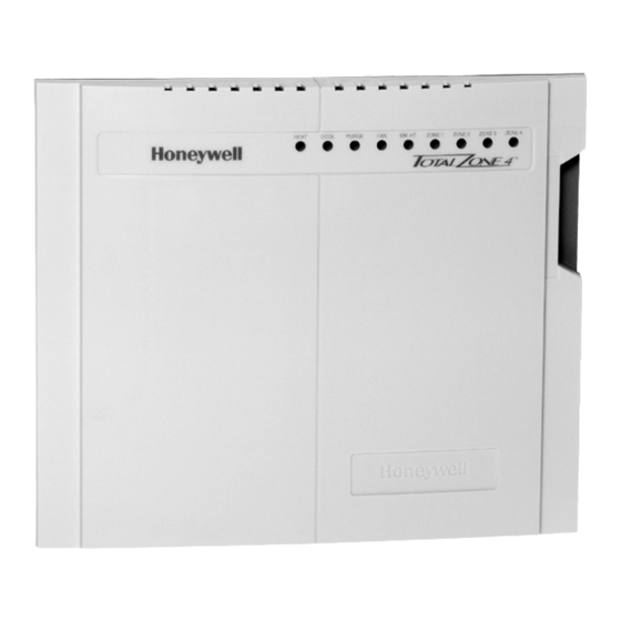
TZ-4 TotalZone® Zone Control Panel
APPLICATION
The TZ-4 TotalZone Zone Control Panel controls single-stage,
multi-stage, conventional or heat pump heat/cool equipment.
It controls 2, 3 or 4 zones, and is expandable up to 32 zones
with optional TotalZone® Add-A-Zone™ Four Zone Control
Panel.
® U.S. Registered Trademark
Copyright © 2002 Honeywell • All Rights Reserved
FEATURES
• Up to three stages heat and two stages cooling can be
controlled by thermostat, built-in timer, or based on
the percentage of zones calling.
• Controls single-stage, multi-stage, conventional, heat
pump or dual-fuel equipment.
• Controls up to four zones and can be expanded up to
32 zones with Add-A-Zone Control Panels.
• Uses Honeywell four-wire, single-stage, multi-stage, or
select heat pump thermostats.
• Zone-A-Lone central setback feature.
• Purge timer protects equipment between calls for heat
or cool with choice of panel or HVAC equipment
controlled fan.
• System and zone damper LEDs indicate system and
damper status.
• Individual zone fan control.
• Discharge Air Temperature Sensor for capacity control
with adjustable high and low limits.
• Thermal circuit breaker protects panel and transformer
from damage if miswired.
For Internet access:
www.honeywellzoning.com
For technical support, call 1-800-828-8367.
To download Zoning literature: http://hbctechlit.honeywell.com
Application.........................................................................
Features ............................................................................
Specifications ....................................................................
Installation .........................................................................
Startup And Checkout........................................................ 12
Operation........................................................................... 12
Troubleshooting................................................................. 17
PRODUCT DATA
Contents
1
1
2
4
68-0259-1
Table of Contents

Related Manuals for Honeywell TotalZone TZ-4


Summary of Contents for Honeywell TotalZone TZ-4
- Page 1 For technical support, call 1-800-828-8367. To download Zoning literature: http://hbctechlit.honeywell.com Contents Application................. Features ................Specifications ..............Installation ................. Startup and Checkout............12 Operation................12 Troubleshooting..............17 ® U.S. Registered Trademark Copyright © 2002 Honeywell • All Rights Reserved 68-0259-1...
-
Page 2: Specifications
TZ-4 TOTALZONE® ZONE CONTROL PANEL SPECIFICATIONS Input Ratings: Wiring: 18-gauge wire for all equipment and system Voltage: 20-30 Vac, 50/60 Hz. connections. Power: 13 VA, nominal. Wiring Connections: Output Ratings: Thermostat: R, C, W1/E, W2, W3/AUX, Y1, Y2, G, L, O/B 1.5A run, 200,000 cycles (30 Vac). - Page 3 Table 2. Recommended Dampers. 40 VA transformers. Use SDCR and 40 VA transformer for additional dampers Honeywell Damper Type Round Rectangular required on one zone. Dampers are connected to M1 Common, M4 Open, and M6...
-
Page 4: Installation
TZ-4 TOTALZONE® ZONE CONTROL PANEL 3. Mount the TZ-4 zone panel near the HVAC equipment; (on a wall or on the cold-air return). See Fig. 2. 4. Level the TZ-4 for appearance only. Table 3. Required Accessories (Not Supplied). Accessory Description Wiring Bypass Rating... - Page 5 TZ-4 TOTALZONE® ZONE CONTROL PANEL Wiring Diagrams (Fig. 3 and 4) Conventional Thermostats Conventional (RWYG) thermostats can be used to control conventional, multi-stage, and heat pump equipment. If the thermostat has a common terminal, it is wired to C on the panel, see Fig.
- Page 6 TZ-4 TOTALZONE® ZONE CONTROL PANEL TZ-4 THERMOSTAT CONNECTORS 24 VAC 120 VAC PC8900 W8900A,C W8900A/C IS RECOMMEDED FOR CONVENTIONAL AND HEAT PUMP APPLICATIONS. THE W8900B CANNOT SWITCH THE PANEL TO EMERGENCY HEAT. LEAVE O/B JUMPER ON TZ-4 DISCONNECTED. M20508B Fig. 4. PC8900 with W8900A,C Thermostat wiring. Heat Pump Thermostats If the PC8900/W8900 /Thermostat is used in a heat pump application, use the W8900A, not the W8900B, and wire as...
- Page 7 TZ-4 TOTALZONE® ZONE CONTROL PANEL ARD or ZD Dampers Wire the ARD or ZD Damper to the panel as shown in Fig. 8. Multiple dampers can be wired in parallel. Use these dampers on systems up to 2000 cfm. AOBD Dampers Wire the AOBD dampers to the panel as shown in Fig.
- Page 8 TZ-4 TOTALZONE® ZONE CONTROL PANEL MOTOR TERMINALS FIELD JUMPER DAMPER MOTOR M19067 TZ-4 THERMOSTAT Fig. 9. Wiring AOBD damper to panel. CONNECTORS MOTOR TERMINALS FIELD JUMPER HEAT PUMP THERMOSTAT WITH SINGLE Y THERMOSTAT WIRING DAMPER MOTORS M19068 COMMON (C) TERMINAL IS USED ONLY ON THERMOSTATS THAT REQUIRE A COMMON WIRE.
- Page 9 TZ-4 TOTALZONE® ZONE CONTROL PANEL ZONE CONTROL PANEL DAMPER TERMINALS ZONE THERMOSTAT TERMINAL ML6161 24 VAC, 40 VA Transformer PANEL R8222 RELAY XFRM DAMPER XFRM M20548 24 VAC, 40 VA Transformer Fig. 12. MARD or ML6161 Damper Motor Actuator using (Required if R8222 Relay wiring.
- Page 10 TZ-4 TOTALZONE® ZONE CONTROL PANEL Conventional Equipment Wire the heating and cooling equipment to the equipment terminals on the TZ-4 Panel as shown in Fig. 16. Conventional Equipment: Set DIP switch 5-1 to on. Electric Furnaces: Set DIP switch 5-6 to off to energize the fan with a call for heat.
- Page 11 TZ-4 TOTALZONE® ZONE CONTROL PANEL Single Transformer Heating/Cooling HEAT COOL PURGE EM. HEAT ZONE 1 ZONE 2 ZONE 3 ZONE 4 systems require a jumper to be installed connecting R and R (factory installed). ZONE LEDs LED STATES: Damper open or opening 30 F 130 F 140 F...
-
Page 12: Operation
TZ-4 TOTALZONE® ZONE CONTROL PANEL Single Transformer Heating/Cooling Single Transformer Heating/Cooling systems require a jumper to be installed systems require a jumper to be installed connecting R and R connecting R and R (factory installed). (factory installed). HVAC Equipment HVAC Equipment Heating Transformer Heating Transformer 24 VAC... -
Page 13: Startup And Checkout
TZ-4 TOTALZONE® ZONE CONTROL PANEL STARTUP AND CHECKOUT After the installation is complete, verify correct operation: Single Transformer Heating/Cooling systems require a jumper to be installed 1. Place the Em Heat switch in the Off (down) position. connecting R and R 2. - Page 14 TZ-4 TOTALZONE® ZONE CONTROL PANEL Purge Mode At the end of every call for heat or cool, the panel enters a DIP Switch bank 4, switches 1-4, are used to configure the Purge mode that holds open the calling zone damper for two staging method: (default) or three and one-half minutes.
- Page 15 TZ-4 TOTALZONE® ZONE CONTROL PANEL HEAT PUMP OPERATION The panel can control single- or two-stage heat pumps with or without auxiliary heat. Set DIP switch 5-1 to Off for heat pump Table 5. DIP Switch Bank 4, Stage 3 Configuration. control.
- Page 16 TZ-4 TOTALZONE® ZONE CONTROL PANEL Thermostat Operation Multi-Stage Thermostats Use multi-stage thermostats to control up to three stages of heat and two stages cool with the W1/E,W2, W3/AUX, Y1, Conventional Thermostats and Y2 thermostat terminals. Conventional (R,W,Y,G) heat/cool thermostats can be used with the TZ-4 to control single or multi-stage gas, electric or oil Manual and Automatic Changeover Thermostats systems and heat pumps with auxiliary heat.
- Page 17 TZ-4 TOTALZONE® ZONE CONTROL PANEL Use DIP switch 5-2 to change cooling limit settings: When the circuit breaker is tripped, none of the LEDs illuminate and the yellow rectangular component located left of the R and C terminals is hot to touch. Remove power to the Cooling Temperature panel for at least five minutes to allow the circuit breaker to Dip Switch...
-
Page 18: Troubleshooting
TZ-4 TOTALZONE® ZONE CONTROL PANEL TROUBLESHOOTING Table 8. Troubleshooting. Symptom Possible Cause Action No LEDs are Illuminated No power to the board. Check for 24 Vac (±10%) across R and C. Transformers out of phase If 48 Vac across R and T1, reverse T1 and T2 wires. Shorted wire. - Page 19 TZ-4 TOTALZONE® ZONE CONTROL PANEL Table 9. LED Indicators. Color Illuminated Not Illuminated Flashing Heat Heat call. No heat calls. High limit reached. Cool Green Cool call. No cool calls. Low limit reached. Purge Amber Purge mode. Not in Purge mode. •...
- Page 20 Automation and Control Solutions Honeywell Honeywell Limited-Honeywell Limitée 1985 Douglas Drive North 35 Dynamic Drive Golden Valley, MN 55422 Scarborough, Ontario M1V 4Z9 Printed in U.S.A. on recycled 68-0259-1 G.H. Rev. 12-02 www.honeywell.com/yourhome paper containing at least 10% post-consumer paper fibers.