GE ÄKTA pure Operating Instructions Manual
Hide thumbs
Also See for ÄKTA pure:
- User manual (522 pages) ,
- Operating instructions manual (160 pages)
Table of Contents
Quick Links
Table of Contents

Related Manuals for GE ÄKTA pure


Summary of Contents for GE ÄKTA pure
- Page 1 ÄKTA ™ pure Operating Instructions Original instructions...
- Page 2 Page intentionally left blank...
-
Page 3: Table Of Contents
Table of Contents Table of Contents Introduction ......................About this manual ..........................Important user information ......................Regulatory information ........................Safety instructions ....................Safety precautions ..........................Labels ................................. Emergency procedures ........................Recycling information ......................... Declaration of Hazardous Substances (DoHS) ................ The instrument and software ................ÄKTA pure instrument overview .................... - Page 4 Table of Contents Run a method ......................Before you start ............................. Applying the sample ..........................Start a method run ..........................Monitor the run ............................After run procedures ........................... Maintenance ......................Reference information ..................System specifications ......................... Chemical resistance guide ....................... Check/Change the Node ID of a module ...................
-
Page 5: Introduction
1 Introduction Introduction About this chapter This chapter contains important user information, description of safety notices, regula- tory information and a general description of the intended use of ÄKTA pure. In this chapter This chapter contains the following sections: Section See page 1.1 About this manual 1.2 Important user information... -
Page 6: About This Manual
1 Introduction 1.1 About this manual About this manual Purpose of the Operating Instructions The Operating Instructions provide you with the instructions needed to install, operate and maintain ÄKTA pure in a safe way. Typographical conventions Software items are identified in the text by bold italic text. A colon separates items in a group, thus Flowpath:Injection valve refers to the Injection valve item in the Flowpath group. -
Page 7: Important User Information
1 Introduction 1.2 Important user information Important user information Read this before operating ÄKTA pure All users must read the entire ÄKTA pure Operating Instructions before installing, operating, or maintaining the instrument. Always keep the ÄKTA pure Operating Instructions at hand when operating ÄKTA pure. Do not operate ÄKTA pure in any other way than described in the Operating Instructions. - Page 8 1 Introduction 1.2 Important user information Safety notices This user documentation contains safety notices (WARNING, CAUTION, and NOTICE) concerning the safe use of the product. See definitions below. WARNING WARNING indicates a hazardous situation which, if not avoided, could result in death or serious injury. It is important not to proceed until all stated conditions are met and clearly understood.
-
Page 9: Regulatory Information
EU Declaration of Conformity (DoC) document. Requirement Content Name and address of manufacturer GE Healthcare Bio-Sciences AB, Björkgatan 30, SE 751 84 Uppsala, Sweden Conformity with EU Directives This product complies with the European directives listed in the table, by fulfilling the corresponding harmonized standards. - Page 10 The user is cautioned that any changes or modifications not expressly approved by GE could void the user’s authority to operate the equipment. This equipment has been tested and found to comply with the limits for a Class A digital device, pursuant to part 15 of the FCC Rules.
- Page 11 • connected to other products recommended or described in the user documentation, • used in the same state as it was delivered from GE, except for alterations described in the user documentation. Regulatory compliance of connected equipment Any equipment connected to ÄKTA pure should meet the safety requirements of EN/IEC...
-
Page 12: Safety Instructions
2 Safety instructions Safety instructions About this chapter This chapter describes safety precautions, safety labels and emergency shutdown pro- cedures for ÄKTA pure. Decommissioning information is also described. In this chapter This chapter contains the following sections: Section See page 2.1 Safety precautions 2.2 Labels 2.3 Emergency procedures... -
Page 13: Safety Precautions
2 Safety instructions 2.1 Safety precautions Safety precautions Introduction The ÄKTA pure instrument is powered by mains voltage and handles pressurized liquids that may be hazardous. Before installing, operating or maintaining the system, you must be aware of the hazards described in this manual. Follow the instructions provided to avoid personal injuries or damage to the equipment. - Page 14 2 Safety instructions 2.1 Safety precautions WARNING Do not use any accessories not supplied or recommended by GE. WARNING Do not use ÄKTA pure if it is not working properly, nor if it has suf- fered any damage, for example: •...
- Page 15 2 Safety instructions 2.1 Safety precautions CAUTION Reversed Phase Chromatography (RPC) runs with 100% acetoni- trile in ÄKTA pure. Always replace the PEEK tubing between the used system pump and the pump pressure monitor with orange PEEK tubing, i.d. 0.5 mm, before running RPC with 100% acetonitrile. The tubing to be replaced is green for 25 ml/min systems and beige for 150 ml/min systems.
- Page 16 Protective ground. The ÄKTA pure instrument must always be connected to a grounded power outlet. WARNING Only use grounded power cords delivered or approved by GE. WARNING Do not block access to the power switch and power cord. The power switch must always be easy to access. The power cord with plug must always be easy to disconnect.
- Page 17 NOTICE Misuse of UniNet-9 connectors. The UniNet-9 connectors at the rear panel should not be confused with Firewire connectors. Only connect GE marked products to the UniNet-9 connectors. Do not disconnect or move the UniNet-9 bus cable. NOTICE Any computer used with the equipment shall comply with IEC 60950 and be installed and used according to the manufacturer's instruc- tions.
- Page 18 2 Safety instructions 2.1 Safety precautions System operation Warnings WARNING Electrical shock hazard after spillage. If there is a risk that large volumes of spilled liquid may penetrate the casing of ÄKTA pure, immediately switch off ÄKTA pure, disconnect the power cord, and contact an authorized service engineer.
- Page 19 2 Safety instructions 2.1 Safety precautions CAUTION Max. weight on Buffer tray. Do not place containers with a volume of more than 5 liters each on the Buffer tray. The total allowed weight on the Buffer tray is 20 kg. CAUTION Disconnect power.
- Page 20 Maintenance Warnings WARNING Electrical shock hazard. All repairs should be done by service personnel authorized by GE. Do not open any covers or replace parts unless specifically stated in the user documentation. ÄKTA pure Operating Instructions 29-0229-97 AE...
- Page 21 2 Safety instructions 2.1 Safety precautions Cautions CAUTION Disconnect power. Always switch off power to the ÄKTA pure in- strument before replacing any of its components, unless stated otherwise in the user documentation. CAUTION Hazardous chemicals and biological agents. Before maintenance, service and decommissioning, wash the ÄKTA pure instrument with a neutral solution to make sure that any hazardous solvents and biological agents have been flushed out from the system.
- Page 22 2 Safety instructions 2.1 Safety precautions Notices NOTICE Cleaning. Keep the ÄKTA pure instrument dry and clean. Wipe regularly with a soft damp tissue and, if necessary, a mild cleaning agent. Let the ÄKTA pure instrument dry completely before use. ÄKTA pure Operating Instructions 29-0229-97 AE...
-
Page 23: Labels
2 Safety instructions 2.2 Labels Labels Introduction This section describes the safety labels that are attached to the ÄKTA pure instrument. For information about marking of the computer equipment, refer to the manufacturer’s instructions. ÄKTA pure instrument label The serial number of the ÄKTA pure instrument is printed on the instrument labels, located on the back of the instrument and below the pump tray on the front of the instrument. - Page 24 2 Safety instructions 2.2 Labels Connector label The connector label is located on the back of the instrument. I/O box E9 instrument label The I/O-box serial number is printed on the I/O-box instrument label, located underneath the I/O-box. Safety symbols The following safety symbols are used in the labels: Label Meaning...
- Page 25 2 Safety instructions 2.2 Labels Label Meaning The system complies with applicable requirements for Australia and New Zealand. The system complies with applicable European direc- tives. This symbol indicates that ÄKTA pure has been certified by a Nationally Recognized Testing Laboratory (NRTL). NRTL means an organization, which is recognized by the US Occupational Safety and Health Administration (OSHA) as meeting the legal requirements of Title 29...
-
Page 26: Emergency Procedures
2 Safety instructions 2.3 Emergency procedures Emergency procedures Introduction This section describes how to perform an emergency shutdown of the ÄKTA pure instru- ment, including connected equipment. This section also describes the results in the event of power failure or network interruption. Emergency shutdown In an emergency situation, stop the run by either pausing the run or switching off the instrument as described below:... - Page 27 2 Safety instructions 2.3 Emergency procedures If you want then... to... switch off the press the Power switch to the 0 position, or • instrument disconnect the power cord from the wall socket. • Result: The run is interrupted immediately. Note: The sample and data may be lost as a result of switching off the power.
- Page 28 2 Safety instructions 2.3 Emergency procedures Power failure to... will result in... Computer The UNICORN computer shuts down • The Power/Communication indicator (white) • on the Instrument control panel displays a slowly flashing light. The run is interrupted immediately • Data generated up to 10 seconds before the •...
-
Page 29: Recycling Information
2 Safety instructions 2.4 Recycling information Recycling information About this section This section describes the procedures for disposal and recycling of ÄKTA pure. Decommissioning and disposal of the equipment When taking ÄKTA pure out of service: • The equipment must be decontaminated. •... -
Page 30: Declaration Of Hazardous Substances (Dohs)
2 Safety instructions 2.5 Declaration of Hazardous Substances (DoHS) Declaration of Hazardous Substances (DoHS) 根据SJ/T11364-2006《电子信息产品污染控制标识要求》特提供如下有关污染 控制方面的信息。 The following product pollution control information is provided according to SJ/T11364-2006 Marking for Control of Pollution caused by Electronic Information Products. 电子信息产品污染控制标志说明 Explanation of Pollution Control Label 该标志表明本产品含有超过SJ/T11363-2006《电子信息产品中有毒有害物质的限... - Page 31 2 Safety instructions 2.5 Declaration of Hazardous Substances (DoHS) 有毒有害物质或元素的名称及含量 Name and Concentration of Hazardous Substances 产品中有毒有害物质或元素的名称及含量 Table of Hazardous Substances’ Name and Concentration 部件名称 有毒有害物质或元素 Component name Hazardous substance 铅 汞 镉 六价铬 多溴联苯 多溴二苯醚 Cr6+ PBDE 29-0182-24 29-0182-25 29-0182-26 29-0182-27 29-0182-28...
-
Page 32: The Instrument And Software
3 The instrument and software The instrument and software About this chapter This chapter gives an overview of ÄKTA pure: instrument, software and accessories. In this chapter This chapter contains the following sections: Section See page 3.1 ÄKTA pure instrument overview 3.2 UNICORN software ÄKTA pure Operating Instructions 29-0229-97 AE... -
Page 33: Äkta Pure Instrument Overview
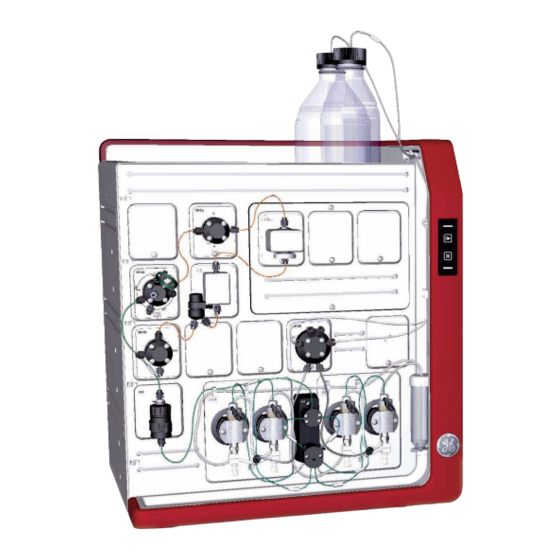
3 The instrument and software 3.1 ÄKTA pure instrument overview ÄKTA pure instrument overview Introduction This section shows an overview of the ÄKTA pure instrument. Technical details about the instrument and the individual modules are found in ÄKTA pure User Manual. Exterior design ÄKTA pure has a modular design, with all liquid handling modules placed on the exterior of the instrument. - Page 34 3 The instrument and software 3.1 ÄKTA pure instrument overview Illustrations of the main parts of the instrument The illustrations below show the location of the main parts of the instrument. Part Function Wet sides Buffer tray Holder rails Instrument control panel Power switch Ventilation panel ÄKTA pure Operating Instructions 29-0229-97 AE...
- Page 35 3 The instrument and software 3.1 ÄKTA pure instrument overview Available modules The modular design allows the user to customize ÄKTA pure in multiple ways. The system is always delivered with the core modules of the selected configuration, but one or more optional modules may be added to the flow path.
- Page 36 3 The instrument and software 3.1 ÄKTA pure instrument overview Module Label in ÄKTA pure 25 ÄKTA pure 150 Outlet valves V9-O V9H-O V9-Os V9H-Os Versatile valve V9-V V9H-V UV monitors U9-L U9-L U9-M U9-M Conductivity monitor External air sensor L9-1.5 L9-1.5 L9-1.2...
- Page 37 3 The instrument and software 3.1 ÄKTA pure instrument overview Core module Description Mixer M9 Mixes the buffers delivered from the system pumps to a homoge- neous buffer composition. Three Mixer chambers are available for ÄKTA pure 25, their volumes are: 0.6 ml, 1.4 ml (mounted at delivery) and 5 ml.
- Page 38 3 The instrument and software 3.1 ÄKTA pure instrument overview Option Module Description Column valve Column valve V9-C or Connects up to five columns to the instru- V9H-C ment, and directs the flow onto one col- umn at a time. Column valve V9-Cs Connects one column to the instrument.
- Page 39 3 The instrument and software 3.1 ÄKTA pure instrument overview Example of a typical configuration of the wet side The descriptions of ÄKTA pure and the work flow in this manual are based on an ÄKTA pure that consists of the modules and parts shown in the illustration below. Part Function Inlet valve...
- Page 40 3 The instrument and software 3.1 ÄKTA pure instrument overview Part Function Injection valve Conductivity monitor Column valve UV monitor Illustration of Instrument control panel The Instrument control panel is located to the right on the front of the instrument. It shows the current status of the system using four LED lights.
- Page 41 3 The instrument and software 3.1 ÄKTA pure instrument overview Status indications The light indicators on the Instrument control panel indicate the current status of ÄKTA pure. The table below describes the different states that can be displayed. Display State Description All light indicators are off.
- Page 42 3 The instrument and software 3.1 ÄKTA pure instrument overview Display State Description Both the Power/Communica- A run is ongoing. tion indicator and Continue button display a constant light. The Power/Communication in- Wash A wash instruction or a pump dicator displays a constant light synchronization is ongoing.
- Page 43 3 The instrument and software 3.1 ÄKTA pure instrument overview Display State Description The Power/Communication in- Alarms and The system has been paused dicator displays a constant light. errors due to an alarm. To resume the and the Alarm and error indica- run, acknowledge the alarm and tor flashes.
-
Page 44: Unicorn Software
3 The instrument and software 3.2 UNICORN software UNICORN software Introduction This section gives an overview of the UNICORN software. It also describes the System Control module. To learn more about System Control and the other three modules Administration, Method Editor and Evaluation, see the UNICORN documentation package. In this section This chapter contains the following sections: Section... -
Page 45: Unicorn Software Overview
3 The instrument and software 3.2 UNICORN software 3.2.1 UNICORN software overview 3.2.1 UNICORN software overview Introduction This section gives a brief overview of the UNICORN software: a complete package for control, supervision and evaluation of chromatography instruments and purification runs. -
Page 46: System Control Module
3 The instrument and software 3.2 UNICORN software 3.2.2 System Control module 3.2.2 System Control module Introduction The System Control module is used to start, view, and control a manual or method run. System Control panes As seen in the following illustration, three panes are shown in the System Control module by default. - Page 47 3 The instrument and software 3.2 UNICORN software 3.2.2 System Control module Process picture The Process Picture displays the current flow path, run parameters and real-time data from monitors during a run. It also allows manual interactions with the system. Color indication is applied in the Process Picture, as is shown in the following illustration and described in the following table.
- Page 48 3 The instrument and software 3.2 UNICORN software 3.2.2 System Control module System Control toolbar buttons The following table shows the System Control toolbar buttons that are referred to in this manual. Button Function Button Function Open Method Navigator. Run. Starts a method run. Opens the Method Naviga- tor where available meth- ods are listed.
-
Page 49: Installation
4 Installation Installation About this chapter This chapter provides the necessary instructions to enable users and service personnel • unpack ÄKTA pure when delivered from the factory • install the instrument • install the computer • install the software Read the entire Installation chapter before starting to install ÄKTA pure. In this chapter This chapter contains the following sections: Section... -
Page 50: Site Preparation
4 Installation 4.1 Site preparation Site preparation Introduction This section describes the site planning and the preparations necessary for the installation of ÄKTA pure. The purpose is to provide planners and technical staff with the data needed to prepare the laboratory for the installation. The performance specifications of the system can be met only if the laboratory environ- ment fulfills the requirements stated in this chapter. -
Page 51: Delivery And Storage
When you receive the delivery • Record on the receiving documents if there is any apparent damage on the delivery box. Inform your GE representative of such damage. • Move the delivery box to a protected location indoors. ÄKTA pure delivery box The ÄKTA pure instrument is shipped in a delivery box with the following dimensions and... - Page 52 4 Installation 4.1 Site preparation 4.1.1 Delivery and storage Storage requirements The delivery box should be stored in a protected place indoors. The following storage requirements must be fulfilled for the unopened box: Parameter Allowed range Ambient temperature, storage -25°C to +60°C Relative humidity up to 90% atmospheric humidity at 40°C for 48 Equipment for transportation...
-
Page 53: Room Requirements
Protective ground. The ÄKTA pure instrument must always be connected to a grounded power outlet. WARNING Only use grounded power cords delivered or approved by GE. WARNING Do not block access to the power switch and power cord. The power switch must always be easy to access. The power cord with plug must always be easy to disconnect. - Page 54 4 Installation 4.1 Site preparation 4.1.2 Room requirements Space requirements The illustration below shows the space recommended for ÄKTA pure with Fraction col- lector F9-R. 63 cm 60 cm 80 cm Min 10 cm 54 cm 32 cm The illustration below shows the space recommended for ÄKTA pure with Fraction col- lector F9-C.
- Page 55 4 Installation 4.1 Site preparation 4.1.2 Room requirements Equipment weight Item Weight ÄKTA pure instrument up to 53 kg Computer approximately 9 kg Monitor approximately 3 kg ÄKTA pure dimensions 630 mm 470 mm ÄKTA pure Operating Instructions 29-0229-97 AE...
-
Page 56: Site Environment
4 Installation 4.1 Site preparation 4.1.3 Site environment 4.1.3 Site environment Introduction This section describes the environmental requirements for installation of ÄKTA pure. Operating conditions The following requirements must be fulfilled: • The instrument is intended for indoor use only. •... - Page 57 4 Installation 4.1 Site preparation 4.1.3 Site environment Component Heat output Total Typically 600 W Maximum 900 W ÄKTA pure Operating Instructions 29-0229-97 AE...
-
Page 58: Power Requirements
Protective ground. The ÄKTA pure instrument must always be connected to a grounded power outlet. WARNING Only use grounded power cords delivered or approved by GE. WARNING Do not block access to the power switch and power cord. The power switch must always be easy to access. The power cord with plug must always be easy to disconnect. - Page 59 4 Installation 4.1 Site preparation 4.1.4 Power requirements Parameter Requirement Typical power consump- 300 VA in state Run tion 165 VA in state Ready 25 VA in state Power-save Maximum power con- 1100 VA sumption Number of sockets 1 socket per instrument, up to 3 sockets for computer equipment Type of sockets EU or US plugs.
-
Page 60: Hardware Installation
Protective ground. The ÄKTA pure instrument must always be connected to a grounded power outlet. WARNING Only use grounded power cords delivered or approved by GE. WARNING Do not block access to the power switch and power cord. The power switch must always be easy to access. The power cord with plug must always be easy to disconnect. -
Page 61: Unpack The Instrument
4 Installation 4.2 Hardware installation 4.2.1 Unpack the instrument 4.2.1 Unpack the instrument Introduction This section describes how to unpack the ÄKTA pure instrument, and how to lift the in- strument onto the bench. CAUTION Heavy object. Use proper lifting equipment, or use two or more persons when moving the instrument. - Page 62 4 Installation 4.2 Hardware installation 4.2.1 Unpack the instrument Step Action Lift off and remove the lid and protective foam. Check the contents in the Buffer tray, and lift off the packages from the tray. Lift off the cardboard hood and remove the protecting material from the instrument.
- Page 63 4 Installation 4.2 Hardware installation 4.2.1 Unpack the instrument Step Action Lift off the tray on the wet side on the front of the instrument to access the instrument handles. ÄKTA pure Operating Instructions 29-0229-97 AE...
- Page 64 4 Installation 4.2 Hardware installation 4.2.1 Unpack the instrument Step Action Prepare for lifting. Use two or more persons and grip the instrument from the front, from the back or from either side (only one side is shown below): ÄKTA pure Operating Instructions 29-0229-97 AE...
- Page 65 4 Installation 4.2 Hardware installation 4.2.1 Unpack the instrument Step Action Lift the instrument over the foam attached to the plywood board, and pull away the board from under the instrument. Dispose of the packaging material in accordance with local regulations. Note: The instrument flow path is filled with 50% ethanol at delivery.
- Page 66 4 Installation 4.2 Hardware installation 4.2.1 Unpack the instrument Part Description ÄKTA pure Operating Instructions DVD packages with Instrument Configuration software and manuals ÄKTA pure Operating Instructions 29-0229-97 AE...
-
Page 67: Install The Computer Equipment
4 Installation 4.2 Hardware installation 4.2.2 Install the computer equipment 4.2.2 Install the computer equipment Introduction The computer is either: • Supplied as a part of the ÄKTA pure delivery • Supplied locally Unpacking and installing Unpack and install the computer according to the manufacturer's instructions. NOTICE Any computer used with the equipment shall comply with IEC 60950 and be installed and used according to the manufacturer's instruc-... -
Page 68: Connect System Units
• Network connection between the computer and the ÄKTA pure instrument. WARNING Only use grounded power cords delivered or approved by GE. CAUTION Supply voltage. Make sure that the supply voltage at the wall outlet corresponds to the marking on the instrument, before con- necting the power cord. - Page 69 4 Installation 4.2 Hardware installation 4.2.3 Connect system units Connector illustration The illustration below shows where the connectors are located on the ÄKTA pure instru- ment. For connectors on the computer equipment, refer to the manufacturer´s documen- tation. Connect power to the ÄKTA pure instrument Follow the instruction below to connect power to the ÄKTA pure instrument.
- Page 70 Note: If the computer has not been supplied by GE and if network configuration is to be used, see Administration and Technical Manual for further information on network settings.
-
Page 71: Prepare Waste Tubing
4 Installation 4.2 Hardware installation 4.2.4 Prepare waste tubing 4.2.4 Prepare waste tubing The table below lists the waste tubing of the instrument and where it is located. Make sure that the waste tubing is connected to the correct positions on the modules. Module Tubing connections Location of tubing... - Page 72 4 Installation 4.2 Hardware installation 4.2.4 Prepare waste tubing Step Action Insert the waste tubing from all installed modules in a vessel. Make sure that the tubing is securely fastened to the ÄKTA pure instrument: Fasten waste tubing from the valves with the clips on the front of the •...
- Page 73 4 Installation 4.2 Hardware installation 4.2.4 Prepare waste tubing Step Action Cut the waste tubing to appropriate length. It is important that the tubing is not bent and will not be submerged in liquid during the run. Note: If the tubing is too short, replace it with new tubing. Do not lengthen the tubing as this might cause obstruction of the tubing.
-
Page 74: Prepare The Pump Rinsing System
4 Installation 4.2 Hardware installation 4.2.5 Prepare the pump rinsing system 4.2.5 Prepare the pump rinsing system Illustration of the pump piston rinsing system The pump piston rinsing system protects the seal that prevents leakage between the pump chamber and the drive mechanism of the pump. The illustration below shows the parts and tubing of the pump piston rinsing system. - Page 75 4 Installation 4.2 Hardware installation 4.2.5 Prepare the pump rinsing system Prime the pump rinsing system Follow the instructions below to fill the pump piston rinsing system with rinsing solution. See the tubing configuration of the rinsing system in the illustration above. Step Action Remove the pump rinsing liquid tube from the holder.
- Page 76 4 Installation 4.2 Hardware installation 4.2.5 Prepare the pump rinsing system Step Action Disconnect the syringe and discard its contents. Insert the outlet tubing into the fluid in the rinsing solution tube. Fill the rinsing solution tube so that the tube contains 50 ml of 20% ethanol. ÄKTA pure Operating Instructions 29-0229-97 AE...
-
Page 77: Start The Instrument And The Computer
4 Installation 4.2 Hardware installation 4.2.6 Start the instrument and the computer 4.2.6 Start the instrument and the computer Introduction This section describes how to start the instrument and the computer. Instruction Follow the instructions below to start the instrument and the computer. Step Action Switch on the instrument by pressing the power switch to the I position. -
Page 78: Software Installation
4 Installation 4.3 Software installation Software installation Introduction This section gives an overview of the different UNICORN installation types. Detailed information about software installation and configuration is available in the Administration and Technical Manual. Software installations UNICORN can be installed as listed below: •... -
Page 79: Start Unicorn And Connect To System
4 Installation 4.4 Start UNICORN and connect to system Start UNICORN and connect to system Introduction This section describes how to start and log on to UNICORN and how to connect the in- strument to UNICORN. Start UNICORN and log on Follow the instructions to start UNICORN and log on to the program. - Page 80 4 Installation 4.4 Start UNICORN and connect to system Step Action In the Log On dialog: select User Name. • enter Password. • Note: It is also possible to select the Use Windows Authentication checkbox and enter a network ID in the User Name field. click OK.
- Page 81 4 Installation 4.4 Start UNICORN and connect to system Connect to system Follow the instructions to connect the instrument to UNICORN. Step Action In the System Control module, click the Connect to Systems button. Result: The Connect to Systems dialog opens. In the Connect to Systems dialog: Select a system check box.
-
Page 82: Prime Inlets And Purge Pump Heads
4 Installation 4.5 Prime inlets and purge pump heads Prime inlets and purge pump heads Introduction Before usage of the system pumps, it is important to: • Prime the inlets (fill the buffer inlets with liquid). • Purge the system pumps (remove air from the pump heads). Note: Note that the procedures described in this section may have to be adapted if your system configuration differs from the one described in this manual. - Page 83 4 Installation 4.5 Prime inlets and purge pump heads Step Action In the Process Picture: Click on the buffer inlets. • Select the position of the inlet to be filled. Select the positions in reverse • alphabetical order and start with the highest number. For example, if all the four inlets in Inlet valve AB are to be filled, fill them in the following order: B2, B1, A2, A1.
- Page 84 4 Installation 4.5 Prime inlets and purge pump heads Step Action Repeat steps 3 to 6 for each piece of inlet tubing that is to be used during the run. Purge System pump B Follow the instruction below to purge both pump heads of System pump B. Step Action Make sure that the piece of waste tubing connected to the Injection valve...
- Page 85 4 Installation 4.5 Prime inlets and purge pump heads Step Action In the Process Picture: Click on the pumps. • Set Conc % B to 100% B. • Click Set % B. • Result: Only System pump B is active. In the Process Picture: Click on the buffer inlets.
- Page 86 4 Installation 4.5 Prime inlets and purge pump heads Step Action In the Process Picture: Click on the Pumps. • Set the System flow to 1.0 ml/min for ÄKTA pure 25 or 10.0 ml/min for • ÄKTA pure 150. Click Set flow rate. •...
- Page 87 4 Installation 4.5 Prime inlets and purge pump heads Step Action Connect the syringe to the purge valve on the right pump head of System pump B, and repeat steps 6 to 8. Keep the system flow running. Validate purge of pump B Follow the instructions below to check that there is no air left in the pump after performing a purge.
- Page 88 4 Installation 4.5 Prime inlets and purge pump heads Step Action Make sure that the pump flow is on. In the Chromatogram pane: Check the PreC pressure curve. If the PreC pressure do not stabilize within a few minutes there may be air left in the pump.
- Page 89 4 Installation 4.5 Prime inlets and purge pump heads End the run Click the End icon in the System Control toolbar to end the run. ÄKTA pure Operating Instructions 29-0229-97 AE...
-
Page 90: Performance Test
4 Installation 4.6 Performance test Performance test Before taking the ÄKTA pure instrument into use, run a performance test to check the function of the equipment. See ÄKTA pure User Manual for further instructions. ÄKTA pure Operating Instructions 29-0229-97 AE... -
Page 91: Activate Power-Save
4 Installation 4.7 Activate Power-save Activate Power-save Introduction ÄKTA pure has a power-save mode. The instrument enters Power-save after having been in the Ready state for a set period of time. The system enters the Ready state when a method run, a method queue or a manual run ends. Enable power-save To enable Power-save, a system must be connected and in state Ready. -
Page 92: Prepare The System For A Run
Always use appropriate personal protective equipment during op- eration and maintenance of ÄKTA pure system. WARNING Do not use any accessories not supplied or recommended by GE. CAUTION Fire Hazard. Before the system is turned on, make sure that there is no unintentional leakage of flammable liquids, or other buffers, in ÄKTA pure or tubing. - Page 93 5 Prepare the system for a run In this chapter This chapter contains the following sections: Section See page 5.1 Before you prepare the system 5.2 Prepare the flow path 5.3 Prime inlets and purge pump heads 5.4 Connect a column 5.5 Pressure alarms 5.6 Prepare for a run at cold room temperature ÄKTA pure Operating Instructions 29-0229-97 AE...
-
Page 94: Before You Prepare The System
5 Prepare the system for a run 5.1 Before you prepare the system Before you prepare the system Introduction It is important to prepare the system in accordance with the settings in the method to be run. Before preparing the system, check the settings in the Method Editor and make sure that all accessories to be used are available. -
Page 95: Prepare The Flow Path
5 Prepare the system for a run 5.2 Prepare the flow path Prepare the flow path Introduction The flow path is defined by the user and may contain tubing, valves, pumps and monitors. This section gives an overview of a flow path and describes how to prepare the flow path before a run. - Page 96 5 Prepare the system for a run 5.2 Prepare the flow path Illustration of the flow path The illustration below shows the flow path for a typical system configuration. The indi- vidual instrument modules are presented in the table below. The configuration of the system is defined by the user.
- Page 97 5 Prepare the system for a run 5.2 Prepare the flow path Part Description Inlet valve System pump B System pump A Pressure monitor Mixer Injection valve Sample loop or Superloop Column valve Column UV monitor Conductivity monitor Flow restrictor Outlet valve Fraction collector W, W1, W2...
- Page 98 5 Prepare the system for a run 5.2 Prepare the flow path Valves and ports Illustrations Outlet valve V9-Os or V9H-Os Waste port: • Note: The waste ports on Out- let valve V9-O and V9H-O are also labelled Note: If the configuration of the ÄKTA pure instrument includes a pH valve (V9-pH or V9H-pH), there will be an additional waste port labelled W3.
-
Page 99: Prime Inlets And Purge Pump Heads
5 Prepare the system for a run 5.3 Prime inlets and purge pump heads Prime inlets and purge pump heads Introduction Before usage of the system pumps, it is important to: • Prime the inlets (fill the buffer inlets with liquid). •... -
Page 100: Connect A Column
5 Prepare the system for a run 5.4 Connect a column Connect a column Introduction This section describes how to connect a column to the instrument using a column holder and without introducing air into the flow path. Several types of column holders are available for ÄKTA pure. - Page 101 5 Prepare the system for a run 5.4 Connect a column Attach a column holder and connect a column Follow the instructions below to connect a column to the instrument. Always use a column holder. If a column valve is used, connect the column to the appropriate A and B ports on the valve.
- Page 102 5 Prepare the system for a run 5.4 Connect a column Step Action In the Process Picture: Click on the Column. • Select Column down flow. • Result: The Column valve switches to position 1. In the Process Picture: Click on the Pumps. •...
- Page 103 5 Prepare the system for a run 5.4 Connect a column Step Action When buffer leaves the tubing in a continuous mode and the top part of the column is filled with buffer, connect the tubing to the top of the column. Connect a piece of tubing to the bottom of the column.
- Page 104 5 Prepare the system for a run 5.4 Connect a column Step Action When buffer leaves the tubing at the bottom of the column in a continuous mode, connect this piece of tubing to the Column valve. Use the port opposite to the one already connected to the column, in this example port 1B.
-
Page 105: Pressure Alarms
5 Prepare the system for a run 5.5 Pressure alarms Pressure alarms Introduction The columns can be protected by two different types of pressure alarms: • The pre-column pressure alarm protects the column hardware • The delta-column pressure alarm (only available when V9-C or V9H-C is installed) protects the column media Column valves V9-C and V9H-C have built-in pressure sensors that automatically measure the pre-column and delta-column pressure. - Page 106 5 Prepare the system for a run 5.5 Pressure alarms Step Action Select Tubing and Delay Volumes • select Tubing: Injection valve to column • Select the inner diameter of the tubing between the injection valve and • the column from the I.D. drop-down list. Type in the tubing Length.
- Page 107 5 Prepare the system for a run 5.5 Pressure alarms For some columns the max delta-column pressure (media) is significantly lower than the max pre-column pressure (hardware). To protect the media if a delta-column pressure measurement is not available (that is, when column valve V9-C or V9H-C is not used), the pre-column pressure alarm must be manually set to the value in the column list that is the lowest of the max pre-column pressure and the max delta-column pressure.
-
Page 108: Prepare For A Run At Cold Room Temperature
5 Prepare the system for a run 5.6 Prepare for a run at cold room temperature Prepare for a run at cold room temperature Introduction When using the instrument in a cold room or cold cabinet, make sure to follow the pre- cautions listed below. -
Page 109: Run A Method
6 Run a method Run a method About this chapter This chapter describes the safety aspects of performing a run and how to shut down and clean the system after a run. For detailed information about how to run the system, see UNICORN System Control Manual. -
Page 110: Before You Start
6 Run a method 6.1 Before you start Before you start Introduction Before starting a run, it is necessary to read and understand the information in this section and to perform the checks listed below. CAUTION Reversed Phase Chromatography (RPC) runs with 100% acetoni- trile in ÄKTA pure. - Page 111 6 Run a method 6.1 Before you start Checklist Make sure that the system is correctly prepared. Check that: • The system is prepared according to the settings in the method to be run. • A suitable column has been selected for the application (consider target protein and pressure range).
- Page 112 6 Run a method 6.1 Before you start If you want to... then... permanently end the run click the End icon. Note: When ending a method run in advance, it is possible to save the partial result. Warnings concerning use of hazardous substances CAUTION Hazardous chemicals during run.
-
Page 113: Applying The Sample
6 Run a method 6.2 Applying the sample Applying the sample Introduction A number of different sample application techniques are available. This section describes sample application using a syringe to manually fill a s loop. The two stages of the sample application are described in the table below. - Page 114 6 Run a method 6.2 Applying the sample Step Action Connect the syringe to the injection valve port Syr. Open the System Control module. In the Process Picture: Click on the Injection valve and select Manual load. • Result: The injection valve switches to manual load position. Load sample into the sample loop.
- Page 115 6 Run a method 6.2 Applying the sample Sample application through a sample loop The method for how to apply a sample can be created beforehand, see Section 6.3 Start a method run, on page116. During sample application, the sample is automatically injected onto the column and the loop is then emptied and washed out using buffer from the system pumps.
-
Page 116: Start A Method Run
6 Run a method 6.3 Start a method run Start a method run Introduction This section describes how to start a run using a previously created method. For further information on method creation, please refer to UNICORN Method Manual. Choose and start a method The instruction below describes how to open a method and start a run. - Page 117 6 Run a method 6.3 Start a method run Step Action Click Start on the last page of the Start Protocol. Result: If column logging was included during installation of UNICORN and a • column type was selected at method creation, the Select Columns dialog opens.
-
Page 118: Monitor The Run
6 Run a method 6.4 Monitor the run Monitor the run Introduction You may follow the on-going method run in the System Control module. The current system status is shown in the System state panel in the Run Data pane. For example, it may state Run, Wash or Hold. -
Page 119: After Run Procedures
6 Run a method 6.5 After run procedures After run procedures Introduction This section describes how to clean the instrument and columns after a chromatographic run, and how to prepare the system for storage. The instrument and the columns should be cleaned between the runs. This will prevent, for example, sample contamination, protein precipitation and column clogging. - Page 120 6 Run a method 6.5 After run procedures • If applicable, clean the pH electrode manually and make sure to leave it in an appro- priate buffer. See ÄKTA pure User Manual for detailed instructions. System storage If the instrument is not going to be used for a couple of days or longer, also perform the following: •...
- Page 121 6 Run a method 6.5 After run procedures In the following situations, in order to increase the lifetime of the pH electrode, use the By-pass position and store the electrode in storage solution inside the pH flow cell: • pH monitoring is not needed during the run. •...
- Page 122 6 Run a method 6.5 After run procedures Shut down the instrument Switch off the instrument by pressing the power switch to the O position. ÄKTA pure Operating Instructions 29-0229-97 AE...
-
Page 123: Maintenance
Maintenance when required WARNING Electrical shock hazard. All repairs should be done by service personnel authorized by GE. Do not open any covers or replace parts unless specifically stated in the user documentation. Periodic maintenance program The following periodic maintenance should be performed by the user of ÄKTA pure. - Page 124 7 Maintenance Interval Maintenance action Weekly Change pump rinsing solution Weekly Replace the inline filter in the Mixer Monthly Check the Flow restrictor Twice a year Clean the UV flow cell Maintenance when required The following maintenance should be performed by the user of ÄKTA pure when required. Maintenance action Clean the instrument externally Perform System CIP...
- Page 125 7 Maintenance Maintenance action Wipe off excess oil from the pump head ÄKTA pure Operating Instructions 29-0229-97 AE...
-
Page 126: Reference Information
8 Reference information Reference information About this chapter This chapter lists the allowed environmental and operational ranges for ÄKTA pure. Refer to ÄKTA pure Product Documentation for detailed technical specifications. In this chapter This chapter contains the following sections: Section See page 8.1 System specifications 8.2 Chemical resistance guide... -
Page 127: System Specifications
8 Reference information 8.1 System specifications System specifications System specifications Parameter Data System configuration Benchtop system, external computer Control system UNICORN 6.4 or other compatible version Connection between PC and instrument Ethernet Dimensions (W x D x H) 535 x 470 x 630 mm Weight (excluding computer) up to 53 kg Power supply... - Page 128 8 Reference information 8.1 System specifications Parameter Data Tubing and connectors ÄKTA pure 25: Inlet: FEP tubing, i.d. 1.6 mm, Tubing • connector 5/16" + Ferrule (yellow), 1/8" Pump to Injection valve: PEEK tubing, • i.d. 0.75 mm, Fingertight connector, 1/16"...
- Page 129 8 Reference information 8.1 System specifications Operating ranges Parameter Data Operating temperature range 4°C to 35°C Relative humidity 20% to 95%, non-condensing Equipment noise level Equipment Acoustic noise level ÄKTA pure instrument < 60 dB A ÄKTA pure Operating Instructions 29-0229-97 AE...
-
Page 130: Chemical Resistance Guide
8 Reference information 8.2 Chemical resistance guide Chemical resistance guide Introduction This section specifies the chemical resistance of ÄKTA pure to some of the most com- monly used chemicals in liquid chromatography. Biocompatibility ÄKTA pure is designed for maximum biocompatibility, with biochemically inert flow paths constructed mainly from titanium, PEEK and highly resistant fluoropolymers and fluoroe- lastomers. - Page 131 8 Reference information 8.2 Chemical resistance guide Assumptions made The ratings are based on the following assumptions: • Synergy effects of chemical mixtures have not been taken into account. • Room temperature and limited overpressure is assumed. Note: Chemical influences are time and pressure dependent. Unless otherwise stated, all concentrations are 100%.
- Page 132 8 Reference information 8.2 Chemical resistance guide Chemical Concentra- CAS no/EC no tion Sodium chloride 7647-14-5/ 231-598-3 Sodium hypochlorite 7681-52-9/231-668-3 If hydrochloric acid, HCl, is used as a cleaning agent when columns are connected to the system, the HCl concentration should not exceed 0.1 M in the pressure sensors. Remember that the ÄKTA pure system has pressure sensors in the column valve V9-C.
- Page 133 8 Reference information 8.2 Chemical resistance guide Chemicals used in reversed phase chromatography (RPC) Continuous use. Chemical Concentra- CAS no/EC no tion Acetonitrile 100% 75-05-8/ 200-835-2 Acetonitrile/Tetrahydrofu- 85%/15% 109-99-9/ 203-726-8 Acetonitrile/water/Trifluo- Max 0.2% roacetic acid (TFA) Ethanol 100% 75-08-1/ 200-837-3 Isopropanol 100% 67-63-0/ 200-661-7...
- Page 134 8 Reference information 8.2 Chemical resistance guide Reducing agents and other additives Continuous use. Chemical Concentra- CAS no/EC no tion Arginine 74-79-3/ 200-811-1 Benzyl alcohol 100-51-6/ 202-859-9 Dithioerythritol (DTE) 100 mM 3483-12-3 / 222-468-7 Dithiothreitol (DTT) 100 mM 3483-12-3 / 222-468-7 Ethylenediaminetetraacetic 100 mM 60-00-4/ 200-449-4...
-
Page 135: Check/Change The Node Id Of A Module
8 Reference information 8.3 Check/Change the Node ID of a module Check/Change the Node ID of a module Introduction Node ID is a unit number designation that is used by the instrument to distinguish be- tween several units of the same type. All standard valves and available optional modules are pre-configured to give the desired function. - Page 136 8 Reference information 8.3 Check/Change the Node ID of a module Module Label Node ID Sample inlet valve V9-IS / V9H-IS Loop valve V9-L / V9H-L Column valve (5-columns) V9-C / V9H-C Pre-column pressure monitor Post-column pressure monitor Column valve (1-column) V9-Cs / V9H-Cs pH valve V9-pH / V9H-pH...
- Page 137 8 Reference information 8.3 Check/Change the Node ID of a module Module Label Node ID I/O-box, 2nd Check/Change the Node ID Step Action If applicable, remove the module according to the instruction in ÄKTA pure User Manual. The Node ID of a module is set by the position of an arrow on a rotating switch at the back of the module.
-
Page 138: Index
Index Index prime inlets, 82, 99 prime inlet tubing B, 82 ÄKTA pure Installation illustrations, 34 hardware, 60 Apply sample, 113 performance test, 90 sample loop, 113 prepare waste tubing, 71 prime and purge pumps, 82 site preparation, 50 software, 78 Conformity, 9 Instrument control panel, 40 CE marking, 11... - Page 139 Index storage of the pH elec- notices, 8 trode, 121 Safety precautions Power requirements, 58 emergency procedures, 26 Power save, 91 introduction, 13 Prepare the system labels, 23–24 connect column, 100 personal protection, 92, 123 prime inlets, 82, 99 Site preparation, 50 purge system pumps, 82, 99 Software overview, 45 Start UNICORN, 79...
- Page 140 Page intentionally left blank...
- Page 141 Page intentionally left blank...
- Page 142 All goods and services are sold subject to the terms and conditions of sale of the company within GE Healthcare which supplies them. A copy of these terms and conditions is available on request. Contact your local GE Healthcare repre- sentative for the most current information.