Table of Contents
Quick Links
G3
A
mini
ccenta
8SP399A - Accenta mini panel with remote
LCD keypad and communicator outputs
EKZ014400A English
Accenta/Optima
Engineer's Manual
G
4
ACCENTA
1
2
3
5
6
4
PA
7
8
9
0
8EP417A - Accenta LCD keypad
1 2 3 4 5 6 7 8
Zonas
G3
A
mini
ccenta
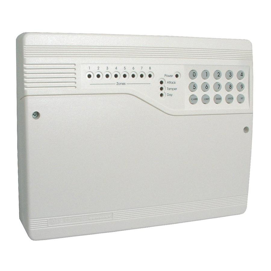
8EP396A Optima Compact panel with
built-in keypad
ZONE
1
5
7
2
3
4
6
8
0
1
2
3
4
5
6
7
8
9
Accenta +
8EP416 - Accenta LED-keypad
0
1
2
3
4
PA
5
6
7
8
9
Honeywell Security
Table of Contents

Related Manuals for Honeywell Accenta


Summary of Contents for Honeywell Accenta
- Page 1 1 2 3 4 5 6 7 8 Zonas ACCENTA mini ccenta mini ccenta 8SP399A - Accenta mini panel with remote 8EP396A Optima Compact panel with LCD keypad and communicator outputs built-in keypad ZONE Accenta + 8EP417A - Accenta LCD keypad...
-
Page 3: Table Of Contents
Table of Contents Accenta/Optima Engineer’s Manual Contents Introduction......................1 Features ........................1 Installation Design ....................2 Fixing the Control Panel ..................3 PCB .......................... 4 Wiring the System ....................4 Tamper Network ..................... 4 Connecting Remote Keypads................5 Fitting the Remote Keypad ................... 6 Security Zones ....................... - Page 4 Accenta/Optima Engineer’s Manual Table of Contents Menu Options....................... 18 0 = Walk Test ........................18 1 = Alarm Test ........................19 2 = Test Outputs ......................... 20 3 = System Flags ........................ 21 4 = Time and Date ....................... 24 5 = Language ........................
-
Page 5: Introduction
Accenta/Optima Engineer’s Manual Features Introduction This manual provides information on Installation design, panel fixing, wiring, power up and programming of the intruder panels. Features 8 zones programmable for Security, 2 zones for Fire. PA input. Tamper input. Outputs for External Siren (Bell) and Strobe. -
Page 6: Installation Design
All of the system wiring is connected directly to the panel. The Accenta panel may be concealed inside a cupboard or loft space, but it must be installed within the protected premises and in a position which is convenient for a mains supply. -
Page 7: Fixing The Control Panel
When positioning the control panel make sure that it is located in a dry place away from damp areas. NOTE: The Accenta Mini enclosure is illustrated here, however the procedures for the other panels is similar. Remove the front cover(s) from the base assembly. -
Page 8: Pcb
As supplied, wire links are fitted across the PA (Personal Alert) and Tamper terminals to represent a closed circuit. Communicator is not fitted Keypad and LEDs (except Power LED) are not to Optima compact panel fitted to Accenta mini panels ABORT +13V 0V FIRE INT SET VOLUME... -
Page 9: Connecting Remote Keypads
Figure 6. Connecting LCD keypads to panel Connecting Remote Keypads NOTE: Where an Accenta Mini panel is being installed, make sure there is at least one remote keypad wired to the panel before the first power up. Up to four remote LCD or LED keypads can be connected to the panel. Wire the keypad(s) as per Figure 5 (LED keypad) or Figure 6 (LCD keypad). -
Page 10: Fitting The Remote Keypad
Accenta/Optima Engineer’s Manual Remote Keypad Fitting the Remote Keypad Separate the RKP baseplate from the main assembly by slackening the retaining screw. Cut away the required thin wall sections around the edges of the baseplate for cable entry. The baseplate may be fitted directly to the wall using screws and wall plugs. If these are not appropriate for the wall then use suitable alternative fixings. -
Page 11: Fire Zone
Accenta/Optima Engineer’s Manual Zones Fire Zone Zones 7 and 8 may be programmed as fire zones. This will automatically exclude the availability of the zone from programs and normal security applications. Panel Board TAMP +13V 0V ire detector Note: ire detector with relay base for output to intruder system. -
Page 12: Pa Circuit
Accenta/Optima Engineer’s Manual PA Circuit PA Circuit It is recommended that no more than 10 Normally Closed type personal attack buttons may be wired in series and then connected to the PA circuit. Operational in Unset and Set, the PA circuit will cause a full alarm condition when activated. PA is indicated on the control panel or RKP. -
Page 13: External Siren (Bell Box) Output
Accenta/Optima Engineer’s Manual External Siren External Siren Output The external siren is usually installed in a high position from where the siren could be seen and heard. Terminal TADB are for connection to the external siren. These terminals provide a power/hold-off supply, sounder trigger and tamper circuit to protect the external siren housing. -
Page 14: Supply Output
Accenta/Optima Engineer’s Manual External Siren (contd) Panel Board STROBE BELL HOLD BATTERY HOLD BATTERY TRIG TRIG Board Board Siren Siren Figure 12. Twin External Siren Wiring 13V Supply Output The 13V output is to power detectors which require a voltage supply (PIR detectors etc). The supply is present at all times and may be used to supply a total load of 350mA. -
Page 15: Remote Signalling Input And Outputs
Accenta/Optima Engineer’s Manual Remote Signalling Remote Signalling Input and Outputs NOTE: These outputs are not applicable to the Optima Compact panel. These terminals have been provided for connection to remote signalling equipment such as a digital communi- cator, or speech dialler. -
Page 16: Filtering Of Intruder Alarms
Accenta/Optima Engineer’s Manual Remote Signalling (contd) Important Notes Each output has been configured as active low. Where the communicator is powered from an external source, not the panel and the outputs are being used without relays, the panel and external power supply will require a common negative supply rail. -
Page 17: Factory Set Condition
Exit time 30 seconds Strobe on setting Entry time 30 seconds Exit mode Timed Flag 3 Accenta Optima Version X.XX Program 2 NOTE: X.XX indicates panel version eg 1.00 Zone 1 Timed Zone 2 Timed inhibit Zone 3 - 8... -
Page 18: Mains Connection
Accenta/Optima Engineer’s Manual Mains Connection Mains Connection The mains power should be connected using 3-core cable of not less than 1 mm sq. from a fused spur to the mains connector inside the control panel. The 2 A fused spur must be located close to the control panel. -
Page 19: First Power Up
Accenta/Optima Engineer’s Manual First Power Up First Power Up NOTE: For Optima Compact, fit the top cover on to the base and connect the speaker wires. Check that the factory fitted links are connected to terminals PA, TAMP and T-A. -
Page 20: Engineer Program Mode
Accenta/Optima Engineer’s Manual Engineer Program Mode Engineer Program Mode The panel may be programmed to suit a wide variety of installations. Once the Engineer program mode has been accessed, each configuration may be changed in any order. Before entering Engineer program mode the system should be unset, with the and indicators lit. -
Page 21: Entering/Exiting Engineer Program Mode
Accenta/Optima Engineer’s Manual Defaulting Entering/Exiting Engineer Program Mode NOTE: The factory configured engineer’s access code is 9999. If however this code is changed then enter the appropriate code. Press LCD Indications LED Indications Enter Your Code 0>Walk test To exit Engineer program mode press... -
Page 22: Menu Options
Accenta/Optima Engineer’s Manual Menu Options Menu Options The full menu structure for the panel can only be accessed while in Engineer program mode. The structure is shown in the following table: MENU OPTIONS 0 = Walk Test 6 = Zone Names... -
Page 23: Alarm Test
Accenta/Optima Engineer’s Manual Alarm Test 1 = Alarm Test This function tests the alarm function of the Bell, Strobe or Sounder. Pressing the appropriate key [1-3] toggles the function ON or OFF. Using the [up arrow] also selects the appropriate alarm function. -
Page 24: Test Outputs
Accenta/Optima Engineer’s Manual Test Outputs 2 = Test Outputs NOTE: These tests are not applicable to Optima Compact panels. This function tests all the outputs on the system. The outputs are:1 = Fire, 2 = PA, 3 = Intruder, 4 = Set, 5 = Abort. -
Page 25: System Flags
Accenta/Optima Engineer’s Manual Test Outputs 3 = System Flags The System Flags are divided into Flags 1, 2 or 3. LCD Keypad: System Flags • Press to display menu System Flags. [3] or • Press [3] or to display the next screen. - Page 26 Accenta/Optima Engineer’s Manual System Flags Flag 1 - Options There are eight options under Flag1 which are described below: 1 = Silent PA When this flag is set to ON, operating SOS will cause a silent alarm. Pressing [1] toggles the flag ON or OFF.
- Page 27 Accenta/Optima Engineer’s Manual System Flags (contd) Flag 2 NOTE: Pressing the [9] key sets all flags ON. Pressing the [0] key sets all flags OFF. Pressing the leaves the function. LCD Keypad: Single Key Set • Press [2] to select System Flag 2. Press [1-2] to toggle flag on or off.
-
Page 28: Time And Date
Accenta/Optima Engineer’s Manual Time & Date 4 = Time and Date LCD Keypad: This option allows the Time or Date to be modified. Pushing key [4] selects the option and the first screen appears as typically below: The Time can be modified in hours, minutes and seconds in the format HH:MM:SS. -
Page 29: Zone Names
Accenta/Optima Engineer’s Manual Timers 6 = Zone Names This option allows each of the eight zones to be given a name from the library (Appendix 2). LCD Keypad: • Press or to go to menu 6>Zone Names. 6>Zone Names •... - Page 30 Accenta/Optima Engineer’s Manual Timers (contd) LED keypad: To change the Bell Time from 15 to 20 minutes: • Press [7] or for option 71 Bell Time. [1] or • Press [1] or for Bell Time in minutes. LED’s 1 and 2 are on.
- Page 31 Accenta/Optima Engineer’s Manual Timers (contd) LED keypad: To change the Bell Delay time from 00 to 12 minutes: • Press [7] to enter Timers.LED’s 1, 2 and 3 are on. • Press [2] for Bell Delay time in minutes. LED’s 1and 2 are on.
-
Page 32: Codes
Accenta/Optima Engineer’s Manual Codes (contd) LED Keypad: To change the Rearm Count: • Press [7] to enter Timers.LED’s 1, 2 and 3 are on. • Press [3] for Rearm Count. LED 1 is on. • Select a number [0 - 9] to change the rearm count. - Page 33 Accenta/Optima Engineer’s Manual Codes (contd) LCD Keypad: To change User code: [8] or then • Press [8] on the keypad or press for Codes. Then press 8>User 1 [1] or • Press the [1] or on the keypad to edit user code.
-
Page 34: C = View Event Log
Accenta/Optima Engineer’s Manual Event Log C = View Event Log 1 = LCD Keypad: The event log gives a display of all the events that have taken place. The events are arranged by date and time. Up to 250 events can be stored in the memory. When the log reaches 250 events and another event takes place, the first event drops out. -
Page 35: O = Omit Allow And Double Knock
Accenta/Optima Engineer’s Manual Event Log (contd) 2 = LED Keypad: The LED keypad is limited to show the last eight set periods with the eighth being the oldest. Zone, indicators will be lit to show zone in alarm . Flashing LED indicates the first zone in alarm. indicates the status of the panel at the time of the alarm. - Page 36 Accenta/Optima Engineer’s Manual Omit Allow & Double Knock LED Keypad: Press to toggle double knock status on or off. Press [9] to turn all double knock zones on. Press [0] to turn all double knock zones off. • Press to enter into menu. LED’s 1 and 2 are on.
- Page 37 Accenta/Optima Engineer’s Manual Omit Allow & Double Knock LED Keypad: Press to toggle omit allow status on or off. Press [9] to turn all omit allow zones on. Press [0] to turn all omit allow zones off. • Press to enter into menu. LED 2 is on.
-
Page 38: P = Programs
Accenta/Optima Engineer’s Manual Programs P = Programs The panel uses three setting routines known as programs. Each program may have a different Exit Mode. These are 0 = Disabled, 1 = Timed, 2 = Final Door or 3 = Silent Timed. Zones can also be assigned different functions in different programs. - Page 39 Accenta/Optima Engineer’s Manual Programs (contd) LCD Keypad: NOTE: Pressing the number toggles the zone ON or OFF While in Engineer program mode, to set up zones as used, • Press to give a choice of programs or press until P>Programs is displayed then press P>Select Program...
- Page 40 Accenta/Optima Engineer’s Manual Programs (contd) 2 = Timed Zones A zone programmed as Timed would be used to protect the main entry/exit door of the entry route. LCD Keypad: NOTE: Pressing the number toggles the zone ON or OFF While in Engineer program mode, to set up zones as timed, •...
- Page 41 Accenta/Optima Engineer’s Manual Programs (contd) 3 = Inhibit Zones This is a zone which, on setting the panel, allows access to the entry/exit zone. However, if the panel is set and a time inhibited zone is triggered before an entry/exit timed zone then an alarm will be generated immediately.
- Page 42 Accenta/Optima Engineer’s Manual Programs (contd) Immediate (Intruder) Zone This is a zone which will, when enabled as used and then activated, go into alarm when the panel is set. To assign a zone as immediate, remove the timed or timed inhibit function and make sure that it is enabled in the Used Zones section.
- Page 43 Accenta/Optima Engineer’s Manual Programs (contd) 5 = Exit Time This is the time allowed to leave the premises via the exit route before the system sets. The programmable range is 00-99 seconds. The actual time is multiplied by 10. If the Exit Time is interrupted within the last 10 seconds, then the Exit Time will restart at 10 seconds after the interruption has cleared.
- Page 44 Accenta/Optima Engineer’s Manual Programs (contd) 6 = Exit Mode This program determines the way the panel functions during the exit time. There are four settings: 0 = Disabled A disabled program is not available for use and cannot be selected at setting time. Program 1 cannot be disabled.
- Page 45 Accenta/Optima Engineer’s Manual Programs (contd) LED Keypad: While in Engineer program mode, to set the Exit Mode , • Press to give a choice of programs.LED’s 1, 2 and 3 are flashing. • Select program 1, 2 or 3. If program 2 is selected, LED 2 is ON.
-
Page 46: Operating The System
Accenta/Optima Engineer’s Manual Operating System Operating the System This section gives a brief description of how to set and unset the system as well as how to reset after an alarm. For further information please refer to the Gen 4 Series User Guide. -
Page 47: Resetting After An Alarm, Tamper Or Pa
Accenta/Optima Engineer’s Manual Operating System (contd) Unsetting the System Sunday 01-Jan LCD Keypad: 10:30 • Enter the premises by the agreed entry route. Thesystem [4-digit code] produces an entry tone. The LED is ON and the LED is OFF indicating that the system is set. - Page 48 Accenta/Optima Engineer’s Manual Operating System (contd) Engineer Reset - LCD Keypad: After a tamper an engineer reset is required if the Engineer Reset flag is enabled. [user code] • Enter your user code [0123] default. Engineer Restore If the system has to be set by an engineer the message Required Engineer Restore Required is displayed.
-
Page 49: Faults
Accenta/Optima Engineer’s Manual Faults Faults Fault conditions are often the result of minor installation errors. Whenever working close to the mains supply or connector, you should exercise extreme caution. Always isolate the mains supply before removing the control panel covers. -
Page 50: Specifications
Accenta/Optima Engineer’s Manual Specs Specifications 8 zones +ve loop, programmable function in each programme Tamper -ve loop, internal sounders in Day - Fill alarm in Set +ve loop,always active External siren (Bell Box) outpout 12V adjustable time (1 - 99 mins) or continuous... -
Page 51: Appendix 1 - Event Log Messages
Accenta/Optima Engineer’s Manual Event Log Appendix 1 - Event Log Messages KEYPAD TEXT DESCRIPTION ZONE EVENTS INTRUDER Intruder zone activated (opened) ENTRY START Entry time started ZONE OMITTED Zone has been omitted for one set period FIRE ZONE Fire zone activated (opened) - Page 52 Accenta/Optima Engineer’s Manual...
-
Page 53: Appendix 2 - Library
Accenta/Optima Engineer’s Manual Library Appendix 2 - Library Attic Kitchen Landing Back Door Basement Living Room Bathroom Lounge Patio Bedroom 1 Bedroom 2 Porch Stairs Bedroom 3 Study Conservatory Dining Room Utility Room Window 1 Fire Zone Window 2 Front Door... - Page 54 Accenta/Optima Engineer’s Manual...
-
Page 55: Servicing Organisation Details
Servicing/Parts Servicing Organisation Details Servicing Organisation name: Telephone number: Date of Installation: Account Number: Parts 8SP399A Accenta mini panel with LCD keypad 8EP396A Optima compact panel 8EP417A Accenta LCD remote keypad 8EP416 Accenta LED remote keypad 8EP276A Informa 8EP289 Extension speaker... - Page 56 Accenta/Optima Engineer’s Manual Engineer Program Mode [PROG] [9] [9] [9] [9]. To exit Engineer Program Mode [RESET] 0 = Walk Test 1 = Alarm Test 1 = Bell 2 = Strobe 3 = Sounder 2 = Test Outputs 1 = Fire...