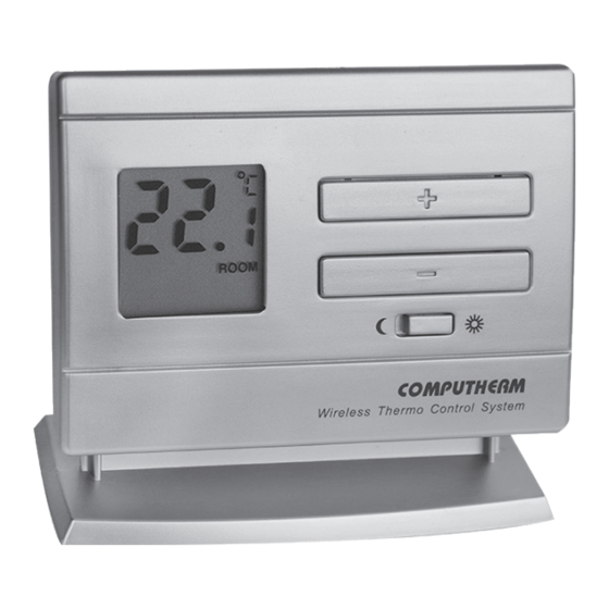
Computherm Q5RF Operating Instructions Manual
Multi-zone wireless (radio-frequency) digital room thermostat
Hide thumbs
Also See for Q5RF:
- Operating instructions (2 pages) ,
- Operating instructions manual (24 pages) ,
- Operating instructions manual (16 pages)
Summary of Contents for Computherm Q5RF
-
Page 1: Operating Instructions
COMPUTHERM Q5RF Multi-zone wireless (radio-frequency) digital room thermostat Operating instructions You can watch the most important aspects of the usage of this thermostat on our video presentation at www.quantrax.hu. - Page 3 The basic package of the device includes two thermostats and a receiver unit. If required, the equipment can be extended by two additional COMPUTHERM Q5RF (TX) or Q8RF (TX) thermostats. The receiver unit receives switching signals from the thermostats, controls the boiler (or air conditioner) and gives commands to open/close the heating zone valves (max.
- Page 4 COMPUTHERM Q1RX socket on our website: www.quantrax.hu) 1. LOCATION OF THE DEVICE The thermostat of the COMPUTHERM Q5RF type device can be freely moved in your residence. It is reasonable to locate it in a room used regularly or for many hours per day so that it is in the direction of natural ventilation in the room but pro- tected from drought or extreme heat (e.g.
-
Page 5: Basic Settings
etc). Its optimal location is 1.5 m above floor level. It can be placed on its own stand or can be mounted on a wall. IMPORTANT WARNING! If the radiator valves in your flat are equipped with a thermostatic head, adjust it to maximum temperature or replace the thermostatic head of the radiator valve with a manual control knob in the room where the room thermostat is to be located, otherwise the thermo- static head may disturb the temperature control of the flat. - Page 6 room temperature value, while the notice “ROOM” appears in the bottom right corner of the display. In this case, the adjusted temperature is visible only during the adjustment process, for approximately 7 seconds after the last button has been pushed. By relocating the plug onto the bottommost and central pins the displayed temperature can be modified so that the display alternately shows the current room temperature and the adjusted temperature for 4...
-
Page 7: Setting The Desired Temperature
„A/C” (cooling) in the bottom left corner of the display, according to the selected mode. 3.4 Calibration of the thermometer of the thermostat You can calibrate the thermometer of the appliance (to correct measured temperature). To this end all you have to do is change the position of the orange-colored potentiometer by a Phillips screwdriver. - Page 8 • Move the switch according to the temperature you would like to change (economy ( w ) or comfort ( ☼ )). • Press the button, after which the no- tice “ROOM” disappears, the notice “SET” (adjusted value) appears in the bottom right corner of the display. Meanwhile, the temperature value shown on the display switches from room tem- perature to the default temperature (18.0 °C/20.0 °C) or to the last set temperature (this temperature is blinking on the display).
-
Page 9: Battery Replacement
6. BATTERY REPLACEMENT The average lifetime of the batteries is 1 year. The icon alternately replacing the temperature value on the display indicates low battery voltage. Replace the batteries whenever the icon indicating low battery voltage appears on the display (see Section 2). After battery replacement, the desired temperature should be adjusted again, because during the battery replacement the thermostat is reset to factory default settings. - Page 10 The receiver unit controls the boiler or air conditioner through a potential- free relay whose connection points are: NO and COM. Connect the two connection points of the heating or cooling equipment to be controlled to terminals NO and COM, i.e. to the normally open terminals of the relay. These connection points become closed following the heating/cooling command of any thermostat.
- Page 11 Thermostat: • Separate the back panel of thermostat OMPUTHERM Q5RF from the front panel by pushing the latch located on the upper side of the case. • Press and hold buttons „LEARN” and „RESET” located inside the ther- mostat smultaneously.
- Page 12 7.3 Resetting synchronization method of thermostat COMPUTHERM Q5RF When you wish to reset operation of thermostat COMPUTHERM Q5RF to default zone 1 then you can reset this option with the following steps: • Press the „RESET” button located inside the thermostat and the button on the front panel simultaneously.
-
Page 13: Frequently Asked Questions
7.6 Manual control of the receiver unit Pressing the “A/M” button separates the thermostats from the receiver unit. In this case, the boiler or air conditioner connected to the receiver unit can only be turned on and off manually, without any temperature inspection. - Page 14 PRODUCT INFORMATION DATA SHEET: • Trademark: • Model identifier: Q5RF • Temperature control class: I. class • Contribution to the efficiency of seasonal space heating: 1% Remark: In addition to using modern temperature regulators, the following up-to-date regulation methods also contribute significantly to the improvement of the...
-
Page 15: Technical Data
TECHNICAL DATA Technical data of the thermostats (transmitters): ‒ adjustable temperature range: 5 to 40 °C (in 0.5 °C increments) ‒ temperature measurement range: 3 to 45 °C (in 0.1 °C increments) ‒ temperature measurement accuracy: ±0.5 °C ‒ temperature calibration range: approx 3 °C ‒... - Page 16 The COMPUTHERM Q5RF type thermostat complies with the requirements of standards RED 2014/53/EU and RoHS 2011/65/EU. QUANTRAX Kft. Manufacturer: Fülemüle u. 34., Szeged, H-6726, Hungary Phone: +36 62 424 133 • Fax: +36 62 424 672 E-mail: [email protected] Web: www.quantrax.hu • www.computherm-hungary.hu...


