Huawei ME909u-521 Hardware Manual
Lte lga module
Hide thumbs
Also See for ME909u-521:
- Acceptance inspection manual (13 pages) ,
- Hardware manual (82 pages) ,
- Hardware migration manual (70 pages)
Table of Contents
Quick Links
Table of Contents

Related Manuals for Huawei ME909u-521


Summary of Contents for Huawei ME909u-521
- Page 1 HUAWEI ME909u-521 LTE LGA Module Hardware Guide Issue Date 2017-12-15...
- Page 2 In order to provide better service, this device will automatically obtain software update information from the Huawei servers after connecting to the Internet. This process will use mobile data, and requires access to your device's unique identifier (IMEI/SN) and the service provider network ID (MCC/MNC) to check whether...
- Page 3 Updated Figure 3-4 power on timing sequence Updated Figure 3-14 recommended circuit of USB interface and its notes 3.11 Updated RF antenna interface 4.4.1 Added Table 4-3 ME909u-521 module GPS main characteristics 5.4.2 Updated power consumption Updated reliability features Updated EMC and ESD features 6.7.3...
- Page 4 HUAWEI ME909u-521 LTE LGA Module Hardware Guide About This Document Document Date Chapter Descriptions Version Deleted electrical features of USIM of issue 5.4.2 Updated Table 5-5 Averaged power off DC power consumption of ME909u-521 Deleted electrical features of application interfaces of issue 02...
-
Page 5: Table Of Contents
HUAWEI ME909u-521 LTE LGA Module Hardware Guide Contents Contents 1 Introduction............................ 8 2 Overall Description ........................9 2.1 About This Chapter ........................... 9 2.2 Function Overview..........................9 2.3 Circuit Block Diagram ........................11 2.4 Application Block Diagram ......................12 3 Description of the Application Interfaces ................13 3.1 About This Chapter ......................... - Page 6 HUAWEI ME909u-521 LTE LGA Module Hardware Guide Contents 3.12 Reserved Interface ........................46 3.13 NC Interface ..........................46 3.14 Tunable Antenna Control ......................47 4 RF Specifications ......................... 48 4.1 About This Chapter ......................... 48 4.2 Operating Frequencies ........................48 4.3 Conducted RF Measurement ......................
- Page 7 HUAWEI ME909u-521 LTE LGA Module Hardware Guide Contents 6.9 Assembly Processes ........................77 6.9.1 General Description of Assembly Processes ................ 77 6.9.2 Stencil Design ........................77 6.9.3 Reflow Profile ........................78 6.10 Specification of Rework ........................ 79 6.10.1 Process of Rework ......................79 6.10.2 Preparations of Rework .......................
-
Page 8: Introduction
This document helps hardware engineer to understand the interface specifications, electrical features and related product information of the ME909u-521 module. If customers want to design a board which is compatible between ME909u-521 module and other 30 mm x30 mm LGA modules, such as MU609, please refer to HUAWEI 30 mm x 30 mm LGA Module Hardware Migration Guide. -
Page 9: Overall Description
HUAWEI ME909u-521 LTE LGA Module Hardware Guide Overall Description Overall Description 2.1 About This Chapter This chapter gives a general description of the ME909u-521 module and provides: Function Overview Circuit Block Diagram Application Block Diagram 2.2 Function Overview... - Page 10 HUAWEI ME909u-521 LTE LGA Module Hardware Guide Overall Description Feature Description Application One standard USIM (Class B and Class C) interface Interface Audio interface: PCM interface (145-pin LGA interface) USB 2.0 (High Speed) 4-wire UART x 2 2-wire UART GPIO (General-Purpose I/O) x 5...
-
Page 11: Circuit Block Diagram
Hardware Guide Overall Description [1]: When the ME909u-521 module works in the range of –30° C to –20° C or +70° C to +75° C , NOT all its RF performances comply with 3GPP specifications. [2]: This is only used for debugging. -
Page 12: Application Block Diagram
HUAWEI ME909u-521 LTE LGA Module Hardware Guide Overall Description 2.4 Application Block Diagram Figure 2-2 Application block diagram of the ME909u-521 module UART Interface: The module supports 3 UART interfaces. Two are 4-wire UARTs. One is 2-wire UART, which is only for debugging. -
Page 13: Description Of The Application Interfaces
NC Interface Tunable Antenna Control 3.2 LGA Interface The ME909u-521 module uses a 145-pin LGA as its external interface. For details about the module and dimensions, see 6.4 Dimensions and Interfaces. Huawei Proprietary and Confidential Issue 05 (2017-12-15) Copyright © Huawei Technologies Co., Ltd. - Page 14 Figure 3-1 shows the sequence of pins on the 145-pin signal interface of the ME909u-521 module. Figure 3-1 Sequence of LGA interface (Top view) Figure 3-2 shows the appearance of ME909u-521 module. The left one is top view, and the right one is bottom view. Huawei Proprietary and Confidential Issue 05 (2017-12-15) Copyright ©...
- Page 15 HUAWEI ME909u-521 LTE LGA Module Hardware Guide Description of the Application Interfaces Figure 3-2 Appearance of ME909u-521 module (without label) Table 3-1 shows the definitions of pins on the 145-pin signal interface of the ME909u-521 module. Table 3-1 Definitions of pins on the LGA interface...
- Page 16 HUAWEI ME909u-521 LTE LGA Module Hardware Guide Description of the Application Interfaces Pin Name Description Parameter Min. Typ. Max. Comments Type Reserved Reserved, must keep this pin open Reserved Reserved, must keep this pin open WAKEUP_IN Host to set the 1.17...
- Page 17 HUAWEI ME909u-521 LTE LGA Module Hardware Guide Description of the Application Interfaces Pin Name Description Parameter Min. Typ. Max. Comments Type Not connected, please keep this pin open Not connected, please keep this pin open Reserved Reserved, must keep this pin open...
- Page 18 HUAWEI ME909u-521 LTE LGA Module Hardware Guide Description of the Application Interfaces Pin Name Description Parameter Min. Typ. Max. Comments Type Not connected, please keep this pin open Not connected, please keep this pin open JTAG_TCK JTAG clock input 1.17 –0.3...
- Page 19 HUAWEI ME909u-521 LTE LGA Module Hardware Guide Description of the Application Interfaces Pin Name Description Parameter Min. Typ. Max. Comments Type Ground Ground Ground Reserved Reserved, must keep this pin open Reserved Reserved, must keep this pin open Reserved Reserved, must...
- Page 20 HUAWEI ME909u-521 LTE LGA Module Hardware Guide Description of the Application Interfaces Pin Name Description Parameter Min. Typ. Max. Comments Type UART0_TX UART0 transmit 1.35 output 0.45 Reserved Reserved, must keep this pin open UART0_RX UART0 receive 1.17 data input –0.3...
- Page 21 HUAWEI ME909u-521 LTE LGA Module Hardware Guide Description of the Application Interfaces Pin Name Description Parameter Min. Typ. Max. Comments Type USIM_CLK USIM clock 1.8/2.8 Reserved Reserved, must keep this pin open Reserved Reserved, must keep this pin open JTAG_RTCK JTAG return clock 1.35...
- Page 22 HUAWEI ME909u-521 LTE LGA Module Hardware Guide Description of the Application Interfaces Pin Name Description Parameter Min. Typ. Max. Comments Type Not connected, please keep this pin open Reserved Reserved, must keep this pin open GPIO General Purpose 1.35 I/O pins. The 0.45...
- Page 23 HUAWEI ME909u-521 LTE LGA Module Hardware Guide Description of the Application Interfaces Pin Name Description Parameter Min. Typ. Max. Comments Type Not connected, please keep this pin open Not connected, please keep this pin open Thermal Ground Pad, this pad need...
- Page 24 HUAWEI ME909u-521 LTE LGA Module Hardware Guide Description of the Application Interfaces Pin Name Description Parameter Min. Typ. Max. Comments Type Thermal Ground Pad, this pad need thermal via Thermal Ground Pad, this pad need thermal via Thermal Ground Pad, this pad need...
-
Page 25: Power Interface
Ground Pad 3.3.2 Power Supply VBAT Interface When the ME909u-521 module works normally, power is supplied through the VBAT pins and the voltage ranges from 3.3 V to 4.2 V (typical value: 3.8 V). The 145-pin LGA provides 2 VBAT pins and 41 GND pins for external power input. To ensure that the ME909u-521 module works normally, all the pins must be used efficiently. -
Page 26: Output Power Supply Interface
10 mA (typical value) for external level conversion or other applications. If the ME909u-521 module is in sleep mode, the output power supply interface is in the low power consumption state (< 500 μA). If the ME909u-521 module is in power down mode, the output power supply is in the disabled state. -
Page 27: Signal Control Interface
HUAWEI ME909u-521 LTE LGA Module Hardware Guide Description of the Application Interfaces 3.4 Signal Control Interface 3.4.1 Overview The signal control part of the interface in the ME909u-521 module consists of the following: Power-on/off (POWER_ON_OFF) pin System reset (RESIN_N) pin ... -
Page 28: Power-On/Off (Power_On_Off) Pin
Hardware Guide Description of the Application Interfaces 3.4.2 Power-on/off (POWER_ON_OFF) Pin The ME909u-521 module can be controlled to be powered on/off by the POWER_ON_OFF pin. Power-On Time Sequence After VBAT has been applied and is stable, the POWER_ON_OFF signal is pulled down, and then the module will boot up. -
Page 29: Resin_N Pin
D+ low If POWER_ON_OFF pin is fixed to be a low state, such as connected to GND, ME909u-521 will automatically start up once power is supplied. Pull-up resistor is never needed for this pin. Figure 3-6 Connections of the POWER_ON_OFF pin 3.4.3 RESIN_N Pin... - Page 30 For example, the AT command automatically reports ^SYSSTART. Figure 3-8 Reset pulse timing The RESIN_N pin must not be pulled down for more than 1s. Otherwise, the ME909u-521 module will be powered off. Huawei Proprietary and Confidential Issue 05 (2017-12-15) Copyright ©...
-
Page 31: Wakeup_In Signal
WAKEUP_IN pin is the authorization signal of ME909u-521 module entering sleep mode. If the signal is pulled up to high level (1.8 V), ME909u-521 module cannot enter sleep mode. If this pin is not connected, it will keep in low level by default. -
Page 32: Sleep_Status Signal
The external devices can get to know whether the module is in sleep mode by reading SLEEP_STATUS pin. When SLEEP_STATUS pin is in high level, ME909u-521 module is in wakeup state. When SLEEP_STATUS pin is in low level, ME909u-521 module is in sleep state. -
Page 33: Led_Mode Signal
HUAWEI ME909u-521 LTE LGA Module Hardware Guide Description of the Application Interfaces Its drive current is no more than 2 mA. Figure 3-12 shows recommended circuit of the SLEEP_STATUS pin. Figure 3-12 Connections of the SLEEP_STATUS pin 3.4.7 LED_MODE Signal If you need the LED function, you need reserve circuit and refer to the following figure till the relative firmware is ready. -
Page 34: Uart Interface
Description of the Application Interfaces 3.5 UART Interface 3.5.1 Overview The ME909u-521 module provides two UART interfaces for asynchronous communication channels. They are UART0 (4-wire UART) and UART1 (4-wire UART), which work as high speed UART by default. The UART2 (2-wire UART) is for debugging only. Customers should layout two test points for them in case of system trouble shooting and analysis. -
Page 35: Circuit Recommended For The Uart Interface
Figure 3-14 Connection of the UART interface in the ME909u-521 module (DCE) with the host (DTE) The RS-232 chip can be used to connect the ME909u-521 module with UART. In this connection, the Complementary Metal Oxide Semiconductor (CMOS) logic level and the Electronic Industries Association (EIA) level are converted mutually. - Page 36 USB_DP USB Data+ defined in the USB 2.0 Specification According to USB protocol, for bus timing or electrical characteristics of ME909u-521 module USB signal, please refer to the chapter 7.3.2 of Universal Serial Bus Specification 2.0. Figure 3-15 Recommended circuit of USB interface...
-
Page 37: Usim Card Interface
Description of the Application Interfaces Since the USB interface of ME909u-521 module supports USB 2.0 high speed, the resistance "RV1 and RV2" in the Figure 3-15 must be Voltage Sensitive Resistor with small capacitance (ALVC18S02003 manufactured by AMOTECH or B72590T7900V60 manufactured by EPCOS is recommended). -
Page 38: Circuit Recommended For The Usim Card Interface
Description of the Application Interfaces 3.7.2 Circuit Recommended for the USIM Card Interface As the ME909u-521 module is not equipped with a USIM socket, you need to place a USIM socket on the user interface board. Figure 3-16 shows the circuit of the USIM card interface. -
Page 39: Audio Interface
The ESD protection component should choose low capacitance. The capacitance of the component should be lower than 10 pF. 3.8 Audio Interface ME909u-521 module provided one PCM digital audio interface. Table 3-9 lists the signals on the digital audio interface. Table 3-9 Signals on the digital audio interface... -
Page 40: General Purpose I/O Interface
Description of the Application Interfaces The ME909u-521 module PCM interface enables communication with an external codec to support linear format. Figure 3-17 Circuit diagram of PCM interface (ME909u-521 module is used as PCM master) PCM_SYNC: Output when PCM is in master mode;... -
Page 41: Jtag Interface
Description of the Application Interfaces 3.10 JTAG Interface The ME909u-521 module provides Joint Test Action Group (JTAG) interface. Table 3-11 shows the signals on the JTAG interface. It is recommended that route out the 9 pins as test points on the DTE for tracing and debugging. -
Page 42: Rf Antenna Interface
MU509, MC509 and MU609. JTAG_SRST_N must be dealt with ESD protection as follow. The 1 kΩ resistor and 4.7 nF capacitor must be placed as close as possible to ME909u-521 module. Figure 3-18 ESD protection of JTAG_SRST_N 3.11 RF Antenna Interface The ME909u-521 module provides three antenna pads (MAIN_ANT, GPS_ANT and AUX_ANT) for connecting the external antennas. - Page 43 HUAWEI ME909u-521 LTE LGA Module Hardware Guide Description of the Application Interfaces Table 3-12 Definition of the antenna pads Min. Typ. Max. Pin Name Description Parameter Comments Type MAIN_ANT RF primary antenna GPS_ANT GPS antenna pad AUX_ANT RF secondary antenna pad Figure 3-19 RF signal trace design about MAIN_ANT for reference (the same for AUX &...
- Page 44 HUAWEI ME909u-521 LTE LGA Module Hardware Guide Description of the Application Interfaces Figure 3-20 RF signal layout design about MAIN_ANT for reference:(the same for AUX & GPS) For the PCB designed by the user, the impedance of all the RF signal tracks must be 50 Ω.
- Page 45 Please use impedance simulation tool to calculate RF MAIN pad impedance. The RF MAIN pad dimension of ME909u-521 is 1.1 mm (L) x 0.9 mm (W). You can get the impedance with lower than 50 Ω calculated by the impedance simulation tool. Since the target impedance is 50 Ω...
-
Page 46: Reserved Interface
79, 91, 92, 102 and 104 3.13 NC Interface The ME909u-521 module has some NC pins. All NC pins should not be connected. Please keep these pins open. Huawei Proprietary and Confidential Issue 05 (2017-12-15) Copyright © Huawei Technologies Co., Ltd. -
Page 47: Tunable Antenna Control
HUAWEI ME909u-521 LTE LGA Module Hardware Guide Description of the Application Interfaces Table 3-14 NC pins Parameter Min. Typ. Max. Pin No. Description Comments Name Type 25, 26, 31, 33, Not connected, 37–41, 82–84, please keep this pin 94–99, 103, open 117–120... -
Page 48: Rf Specifications
HUAWEI ME909u-521 LTE LGA Module Hardware Guide RF Specifications RF Specifications 4.1 About This Chapter This chapter describes the RF specifications of the ME909u-521 module, including: Operating Frequencies Conducted RF Measurement Conducted Rx Sensitivity and Tx Power ... -
Page 49: Conducted Rf Measurement
The instrument compensation needs to be set according to the actual cable conditions. 4.3.2 Test Standards Huawei modules meet 3GPP test standards. Each module passes strict tests at the factory and thus the quality of the modules is guaranteed. 4.4 Conducted Rx Sensitivity and Tx Power 4.4.1 Conducted Receive Sensitivity... -
Page 50: Conducted Transmit Power
4.4.2 Conducted Transmit Power The conducted transmit power is another indicator that measures the performance of ME909u-521 module. The conducted transmit power refers to the maximum power that the module tested at the antenna pad can transmit. According to the 3GPP protocol, the required transmit power varies with the power class. -
Page 51: Antenna Design Requirements
In addition, the transmission line from the antenna port of ME909u-521 module to the antenna is also part of the antenna. The line loss increases with the line length and the frequency. It is recommended that the line loss is as low as possible. - Page 52 Antenna direction The primary antenna must be placed as near as possible to the ME909u-521 module to minimize the line length. The secondary antenna needs to be installed perpendicularly to the primary antenna. The secondary antenna can be placed farther away from the ME909u-521 module.
- Page 53 We must notice that GPS signal is coming from the satellite in the outer space, it means that the incident waves are over our head. The following radiation patterns are recommended for the antenna of ME909u-521 module. ...
-
Page 54: Interference
RF transmission cable into account when measuring any of the preceding antenna indicators. Huawei cooperates with various famous antenna suppliers who are able to make suggestions on antenna design, for example, Amphenol, Skycross, etc. 4.5.2 Interference Besides the antenna performance, the interference on the user board also affects the radio performance (especially the TIS) of the module. -
Page 55: Co-Exsitence With 5 Ghz Wifi Design Guide
VSWR recommended 4.6 Co-exsitence with 5 GHz WIFI Design Guide 4.6.1 Purpose ME909u-521 module supports LTE Band 1/Band 2/Band 3, GSM 1800 and GSM 1900, and each of that band can generate the 2 or 3 harmonic with the frequency about 5 GHz, so that will deteriorate 5 GHz WIFI receiver performance. - Page 56 Network PCB Placement Suggestion For PCB placement, we recommend to keep 5 GHz WIFI antenna away from ME909u-521 module and its main antenna as far as possible. Huawei Proprietary and Confidential Issue 05 (2017-12-15) Copyright © Huawei Technologies Co., Ltd.
- Page 57 HUAWEI ME909u-521 LTE LGA Module Hardware Guide RF Specifications The recommend isolation between ME909u-521 module and WIFI antenna is above 30 dB. The recommend isolation between ME909u-521 antenna and WIFI antenna is above 30 dB. Huawei Proprietary and Confidential Issue 05 (2017-12-15) Copyright ©...
-
Page 58: Electrical And Reliability Features
EMC and ESD Features 5.2 Absolute Ratings Table 5-1 lists the absolute ratings for the ME909u-521 module. Using the ME909u-521 module beyond these conditions may result in permanent damage to the module. Table 5-1 Absolute ratings for the ME909u-521 module... -
Page 59: Operating And Storage Temperatures
Ambient temperature for storage ° C [1]: When the ME909u-521 module works in the range of –30° C to –20° C or +70° C to +75° C , NOT all its RF performances comply with 3GPP specifications. 5.4 Power Supply Features 5.4.1 Input Power Supply... -
Page 60: Power Consumption
Table 5-5 to Table 5-9 . The power consumption listed in this section are tested when the power supply of ME909u-521 module is normal voltage (3.8 V), and all of test values are measured at room temperature. Table 5-5 Averaged power off DC power consumption of ME909u-521 Description Test Value (µA) - Page 61 USB is in active. Radio Off All bands Module is powered up. RF is disabled. USB is in active. Table 5-7 Averaged Data Transmission DC power consumption of ME909u-521 (WCDMA/HSDPA/LTE) Description Band Test Value (mA) Notes/Configuration Typical WCDMA Band 1 (IMT2100)
- Page 62 HUAWEI ME909u-521 LTE LGA Module Hardware Guide Electrical and Reliability Features Description Band Test Value (mA) Notes/Configuration Typical Band 5 0 dBm Tx Power (850 MHz) 10 dBm Tx Power 23.5 dBm Tx Power Band 8 0 dBm Tx Power...
- Page 63 10 dBm Tx Power 23 dBm Tx Power LTE Band 20 0 dBm Tx Power 10 dBm Tx Power 23 dBm Tx Power Table 5-8 Averaged DC power consumption of ME909u-521 (GPRS/EDGE) Test Value (mA) Description Configuration Typical 1 Up/1 Down...
- Page 64 HUAWEI ME909u-521 LTE LGA Module Hardware Guide Electrical and Reliability Features Test Value (mA) Description Configuration Typical 2 Up/1 Down 4 Up/1 Down 1 Up/1 Down 2 Up/1 Down 4 Up/1 Down GPRS 1900 1 Up/1 Down 2 Up/1 Down...
-
Page 65: Reliability Features
The above values are the average of some test samples. 5.5 Reliability Features Table 5-10 lists the test conditions and results of the reliability of the ME909u-521 module. Table 5-10 Test conditions and results of the reliability of the ME909u-521 module... - Page 66 HUAWEI ME909u-521 LTE LGA Module Hardware Guide Electrical and Reliability Features Item Test Condition Standard Sample Results size Temperature: –30º C Low-temperature IEC6006 3 pcs/group Visual inspection: ok operating 8-2-1 Operation mode: working Function test: ok with service connected RF specification: ok ...
- Page 67 HUAWEI ME909u-521 LTE LGA Module Hardware Guide Electrical and Reliability Features Item Test Condition Standard Sample Results size Sine vibration Frequency range: 5 Hz to JESD22- 3 pcs/group Visual inspection: ok 200 Hz B103-B Function test: ok Acceleration: 1 Grms RF specification: ok ...
-
Page 68: Emc And Esd Features
The following are the EMC design comments: Attention should be paid to static control in the manufacture, assembly, packaging, handling, storage process to reduce electrostatic damage to HUAWEI module. RSE (Radiated Spurious Emission) may exceed the limit defined by EN301489 if the antenna port is protected by TVS (Transient Voltage Suppressor), which is resolved by making some adjustment on RF match circuit. - Page 69 Effective shielding measures must be taken on the ESD sensitive materials that are transported or stored outside the EPA. ME909u-521 module does not include any protection against overvoltage. Huawei Proprietary and Confidential Issue 05 (2017-12-15) Copyright © Huawei Technologies Co., Ltd.
-
Page 70: Mechanical Specifications
HUAWEI ME909u-521 LTE LGA Module Hardware Guide Mechanical Specifications Mechanical Specifications 6.1 About This Chapter This chapter describes the process design and mechanical specifications: Storage Requirement Moisture Sensitivity Dimensions and Interfaces Packaging Label Customer PCB Design ... -
Page 71: Dimensions And Interfaces
HUAWEI ME909u-521 LTE LGA Module Hardware Guide Mechanical Specifications Table 6-1 Baking parameters Baking Temperature Baking Condition Baking Duration Remarks Relative humidity ≤ 60% 125° C± 5° C 8 hours Moving, storing, and processing the product must comply with IPC/JEDEC J-STD-033. -
Page 72: Packaging
HUAWEI ME909u-521 LTE LGA Module Hardware Guide Mechanical Specifications 6.5 Packaging HUAWEI LGA module uses five layers ESD pallet, anti-vibration foam and vacuum packing into cartons. The following figure shows the packaging. Module quantity per tray: 5 x 9 = 45 pcs/tray Use vacuum packages;... -
Page 73: Label
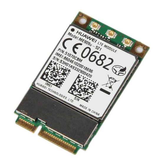
HUAWEI ME909u-521 LTE LGA Module Hardware Guide Mechanical Specifications 6.6 Label The label is made from deformation-resistant, fade-resistant, and high-temperature-resistant material and is able to endure the high temperature of 260° C. Figure 6-2 ME909u-521 label The picture mentioned above is only for reference. -
Page 74: Solder Mask
Mechanical Specifications Figure 6-3 Footprint design of customer’s PCB (Unit: mm) The RF pad difference is the most important difference between HUAWEI LGA modules, please refer to HUAWEI 30 mm x 30 mm LGA Module Hardware Migration Guide. 6.7.3 Solder Mask NSMD is recommended. -
Page 75: Thermal Design Solution
(for details, see Power Consumption). To improve the module reliability and stability, focus on the thermal design of the device to speed up heat dissipation. For thermal characteristics of the ME909u-521 module, you can refer to Operating and Storage Temperatures. - Page 76 HUAWEI ME909u-521 LTE LGA Module Hardware Guide Mechanical Specifications Conductive material should be as thin as possible. − The recommended material of the enclosure is metallic materials, especially − you can add pin fin on the enclosure surface. If the heat sink is installed above the shielding case, you should attach the −...
-
Page 77: Assembly Processes
See the following figure: Figure 6-7 Recommended stencil design of LGA module (Unit: mm) The stencil design has been qualified for HUAWEI motherboard assembly, customers can adjust the parameters by their motherboard design and process situation to assure LGA soldering quality and no defect. -
Page 78: Reflow Profile
HUAWEI ME909u-521 LTE LGA Module Hardware Guide Mechanical Specifications 6.9.3 Reflow Profile For the soldering temperature of the LGA module, see the following figure. Figure 6-8 Reflow profile ° C 235° CPage 79: Specification Of Rework
HUAWEI ME909u-521 LTE LGA Module Hardware Guide Mechanical Specifications 6.10 Specification of Rework 6.10.1 Process of Rework 6.10.2 Preparations of Rework Remove barrier or devices that can’t stand high temperature before rework. If the device to be reworked is beyond the storage period, bake the device according to Table 6-1 .Page 80: Welding Area Treatment
HUAWEI ME909u-521 LTE LGA Module Hardware Guide Mechanical Specifications The LGA module has many solder pads and the pads are large. Therefore, common soldering irons and heat guns cannot be used in the rework. Rework must be done using either infrared heating rework stations or hot air rework stations.Page 81: Specifications Of Rework
HUAWEI ME909u-521 LTE LGA Module Hardware Guide Mechanical Specifications It is recommended that a special clamp be used to pick the module when the module is installed on the pad after applied with some solder. A special rework device must be used for the rework.Page 82: Certifications
7.1 About This Chapter This chapter gives a general description of certifications of ME909u-521. 7.2 Certifications Table 7-1 shows certifications the ME909u-521 has been implemented. For more demands, please contact us for more details about this information. Table 7-1 Product Certifications...Page 83: Safety Information
HUAWEI ME909u-521 LTE LGA Module Hardware Guide Safety Information Safety Information Read the safety information carefully to ensure the correct and safe use of your wireless device. Applicable safety information must be observed. 8.1 Interference Power off your wireless device if using the device is prohibited. Do not use the wireless device when it causes danger or interference with electric devices.Page 84: Traffic Security
HUAWEI ME909u-521 LTE LGA Module Hardware Guide Safety Information Area indicated with the "Power off bi-direction wireless equipment" sign Area where you are generally suggested to stop the engine of a vehicle 8.4 Traffic Security Observe local laws and regulations while using the wireless device. To prevent accidents, do not use your wireless device while driving.Page 85: Laws And Regulations Observance
8.13 EU Regulatory Conformance Statement Hereby, Huawei Technologies Co., Ltd. declares that this device is in compliance with the essential requirements and other relevant provisions of Directive 2014/53/EU. The most recent, effective version of the DoC (Declaration of Conformity) can be viewed at http://consumer.huawei.com/certification.- Page 86 HUAWEI ME909u-521 LTE LGA Module Hardware Guide Safety Information Observe national and local regulations where the device is used. This device may be restricted for use, depending on the local network. Frequency Bands and Power (a) Frequency bands in which the radio equipment operates: Some bands may not be available in all countries or all areas.
Page 87: Appendix A Circuit Of Typical Interface
HUAWEI ME909u-521 LTE LGA Module Hardware Guide Appendix A Circuit of Typical Interface Appendix A Circuit of Typical Interface J302 C371 22pF C365 22pF SMA6251A1_060_20GHT50GH_50 J301 J303 C372 22pF C366 22pF These are impedance matching circuit, the specific capacitance WL629D3_T01_TR_A...Page 88: Appendix B Acronyms And Abbreviations
HUAWEI ME909u-521 LTE LGA Module Appendix B Acronyms and Hardware Guide Abbreviations Appendix B Acronyms and Abbreviations Acronym or Abbreviation Expansion 3GPP Third Generation Partnership Project 8PSK 8 Phase Shift Keying Auxiliary Bit Error Rate BLER Block Error Rate BIOS...- Page 89 HUAWEI ME909u-521 LTE LGA Module Appendix B Acronyms and Hardware Guide Abbreviations Acronym or Abbreviation Expansion Electrostatic Discharge European Union Federal Communications Commission GMSK Gaussian Minimum Shift Keying GPIO General-purpose I/O GPRS General Packet Radio Service Global Positioning System Global System for Mobile Communication...
- Page 90 HUAWEI ME909u-521 LTE LGA Module Appendix B Acronyms and Hardware Guide Abbreviations Acronym or Abbreviation Expansion Radio Frequency Restriction of the Use of Certain Hazardous RoHS Substances Short Message Service To Be Determined Total Isotropic Senstivity Total Radiated Power TTFF...