Table of Contents
Quick Links
Table of Contents

Related Manuals for Keysight E6610A


Summary of Contents for Keysight E6610A
- Page 1 User and Programming Guide Keysight Remote Radio Head Tester E6610A...
- Page 2 Copyright Notice HEREIN. SHOULD KEYSIGHT AND THE public to use, modify, reproduce, © Keysight Technologies 2013 - 2016 USER HAVE A SEPARATE WRITTEN release, perform, display, or disclose No part of this manual may be...
- Page 3 This chassis. that the line cord is connected to a product must be used in a normal Keysight products are designed for use properly-grounded power receptacle. condition (in which all means for with electrical signals that are rated Inspect the connecting cables, test protection are intact) only.
- Page 4 Do not dispose in domestic household waste. PRODUCT MARKINGS: To return unwanted products, contact your local Keysight office, or for more information see http://about.keysight.com/en/companyinfo/e The CE mark is a registered trademark nvironment/takeback.shtml.
-
Page 5: Table Of Contents
Front Panel connections Rear Panel connections 5 GUI Installation and Initial Start-up Turn On Hardware Connect to the E6610A with the GUI Software Using the Search Function Manual Entry of Host Name or IP Address First-time Start-up Check and Update Firmware... - Page 6 SOURCE Subsystem Commands SENSE Subsystem Commands TRACE Subsystem Commands TRIGGER sub-system commands Example Sequence of SCPI commands for E6610A set-up and Measurement E6610A Configuration E6610A Measurements Appendix A: Selecting Attenuation and Power Levels 12 Appendix B: Connecting to Multiple E6610As...
-
Page 7: Document Overview
E6610A Startup Guide for detailed information on how to download and install the GUI software and set up the E6610A to conduct a simple RF loopback test to verify operation. This document contains a less detailed version of the GUI software setup instructions beginning with the section GUI Installation and Initial Start-up. - Page 8 Keysight E6610A User and Programming Guide...
-
Page 9: Referenced And Related Documents
2 Referenced and Related Documents 2 Referenced and Related Documents E6610-90001 Quick Start Poster E6610-90002 E6610A Startup Guide Keysight E6610A User and Programming Guide... - Page 10 Keysight E6610A User and Programming Guide...
-
Page 11: Introduction To The Remote Radio Head Tester
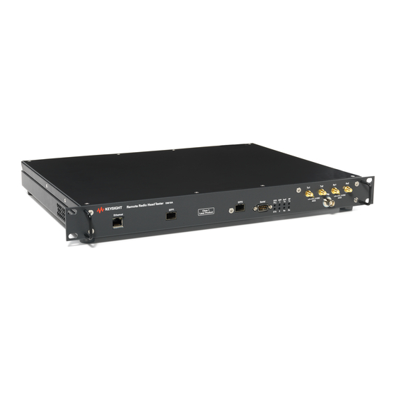
1U (rack unit) high box. It was designed to satisfy the needs of manufacturing test users. The E6610A contains all of the necessary RF and baseband functionality for fast, repeatable and traceable testing of remote radio heads. The inclusion of a small form-factor pluggable (SFP) interface enables direct optical connection to remote radio heads. - Page 12 Keysight E6610A User and Programming Guide...
-
Page 13: E6610A Instrument Connectivity
RF output port, SMA female 3.5mm, 50Ω nominal RF output port, SMA female 3.5mm, 50Ω nominal Trig Reserved for future use, BNC female, 50Ω nominal RF input port, SMA female 3.5mm, 50Ω nominal RF input port, SMA female 3.5mm, 50Ω nominal Keysight E6610A User and Programming Guide... -
Page 14: Rear Panel Connections
10 MHz IN Frequency reference input, 10 MHz, AC coupled square or sine wave. Lock range: + 50 ppm (relative to internal TCXO), 0 dBm nom- inal, 50Ω BNC female. Keysight E6610A User and Programming Guide... -
Page 15: Gui Installation And Initial Start-Up
DHCP function or to a site network. 2. Turn on the E6610A. All 8 LEDs will be orange initially, then all of the LEDs will turn off except for the “SYS PLL” LED, and finally the "AxC Tx" LED will be orange. -
Page 16: Connect To The E6610A With The Gui Software
"Disconnected" to "Connected." First-time Start-up If this is the first time you have set up the E6610A, continue with the steps below to check and update the firmware if needed and install software licenses. If those steps... -
Page 17: Check And Update Firmware
"Setting Up Measurements". Check and Update Firmware In the E6610A GUI, go to the menu bar and select Instrument > Update Firmware to open the Update Firmware window, shown below. Under "Firmware Compatibility," you should see a message indicating whether the firmware is compatible with the current version of the GUI software. - Page 18 5 GUI Installation and Initial Start-up To perform bit error rate measurements, a license is required for E6610A option BR1. To check what licenses are currently installed in the instrument, in the GUI software, go to the menu bar and select Instrument > Licensing to open the "License Management"...
- Page 19 5. Click the Install button to install the licenses into the E6610A. 6. Close the "License Management" window. Click the Disconnect button, then click the Connect button to reconnect to the E6610A. This will cause the GUI software to validate the installed licenses and enable the features.
- Page 20 Keysight E6610A User and Programming Guide...
-
Page 21: Hardware Connections
2. Connect AC power to the E6610A and an appropriate power supply to the RRH. 3. Insert SFP or SFP+ transceivers into the SFP1 port in the E6610A and the RRH's SFP port. Be sure to push the connectors all the way in; you will usually feel/hear a click. - Page 22 Tx/Rx system testing two antenna paths in the RRH. If you are setting up a single channel system, omit the connections between Tx2 and Rx2 on the E6610A and the RRH. Your equipment setup may differ from this diagram depending on the device under test.
-
Page 23: Setting Up Measurements
Turn On Hardware 1. Turn on the E6610A. All 8 LEDs will be orange initially, then all of the LEDs will turn off except for the “SYS PLL” LED, and finally the "AxC Tx" LED will be orange. Note that the "SYS PLL" LED will be green instead of orange when an external reference signal... -
Page 24: Using The Search Function
To use the IP address, type the IP address of the E6610A (e.g. 10.122.34.151) into the box to the right of the Search button. If you do not know the IP address of the E6610A, follow these steps to find the address. -
Page 25: Configure Signal Generation And Analysis Parameters
7 Setting up Measurements 2. Send a ping command for the serial number of the desired E6610A fol- lowed the subnet address, e.g. type "ping KR56180110.companyX.com". 3. The results from the ping command will show the instrument's IP address. Click the Connect button. You will see a message when the connection is done, and the connection status displayed in the bar at the bottom of the GUI window... -
Page 26: Configure Cpri Parameters
4. Set the CPRI line rate. The default value of "Auto Negotiate" will allow the E6610A and the RRH to negotiate a rate. To set a specific rate, choose the value from the drop-down menu and then click the "Re-sync" button. The CPRI diagnostic window will open and show the status of the line rate syn- chronization process as well as the actual line rate achieved. -
Page 27: Configure Cpri Tx And Rx
7 Setting up Measurements Configure CPRI Tx and Rx Click the "CPRI" tab to configure settings for the two CPRI transmitters and receivers. Keysight E6610A User and Programming Guide... - Page 28 N7624B LTE FDD or N7625B LTE TDD Signal Studio applications (requires valid Signal Studio licenses for download to the E6610A). To load waveform files into the E6610A, go to the menu bar in the GUI and select Instru- ment > Waveform Manager. See this topic in the...
-
Page 29: Configure Rf Rx Ports
— Ext Attn (dB): Enter the external attenuation in your test setup between the Tx output of the RRH and the RF Rx input of the E6610A. This value should be entered before setting the Level. This information will be combined with the... -
Page 30: Configure Rf Tx Ports
— Level (dBm): Enter the power level at the Tx output of the RRH. This information will be combined with the "Ext Attn" setting to allow the E6610A to auto- matically adjust its input attenuation and gain to optimize Rx measurements. -
Page 31: Configure Trigger And Reference Settings
— Ext Attn (dB): Enter the external attenuation in your test setup between the RF Tx output of the E6610A and the Rx input of the RRH. This value should be entered before setting the Level. The E6610A will use this information com- bined with the "Level (dBm)"... -
Page 32: Configure Measurement Windows
The screenshots below show the different measurements available for the CPRI Rx and RF Rx captures. Additional measurement configuration choices will appear in the menu bar after a measurement window has been opened. Keysight E6610A User and Programming Guide... -
Page 33: Commit Settings To E6610A
C&M CPRI channel for pass-through of Ethernet packets. Determine the IP Address of the RRH To find the IP address of the RRH, establish a connection to the E6610A SCPI Server and query the E6610A for the IP address. This can be done using a terminal emulation program such as the freeware program PuTTY (download from www.putty.org), which... -
Page 34: Establish Telnet Session To Rrh
7 Setting up Measurements Click "Open" to open the terminal window. It will be blank. Tell the SCPI server the IP address of the E6610A by typing the SCPI command CONTrol:INST:IPADdress xxx.xxx.xxx.xxx, where the x’s are replaced by the IP address of the E6610A. -
Page 35: Initiate E6610A Measurements
All open measurement windows will be updated with each capture. The green arrow changes to a red circle while captures are occurring. Click the red circle to stop data captures and measurement updates. Keysight E6610A User and Programming Guide... - Page 36 Keysight E6610A User and Programming Guide...
-
Page 37: Gui Menus And Measurement Displays
(*.xml) file, which contains the settings for CPRI Tx/Rx, RF Tx/Rx, and measurement windows. Note that any settings changes must be committed to the E6610A before they will be saved as part of the instrument state. -
Page 38: Instrument Menu
Connect: This serves the same function as the "Connect" button on the GUI. The software will connect to the E6610A with the host name or IP address selected in the box to the right of the "Search" button. A message will be displayed to report whether the connection was successful. - Page 39 8 GUI Menus and Measurement Displays Input synchronization signal: Sets the E6610A to use the signal at the rear panel SYNC IN input as an external trigger. Output synchronization signal: Sets the E6610A to output a periodic signal at the rear panel SYNC OUT connector that is aligned with the start of each LTE frame.
- Page 40 Detailed instructions for redeeming and installing licenses may be found in the E6610A Startup Guide. This procedure is also described in the section titled Installation and Startup, under the heading "Installing Software Licenses."...
- Page 41 E6610A Technical Overview. These waveforms may only be used if the appropriate N5121A LTE FDD or N5122A LTE TDD licenses are installed in the E6610A. These files are selected by choosing TM 1.1, TM 3.1, or FRC-A3 from the "Waveform" drop-down menu in the CPRI Tx or RF Tx settings.
- Page 42 RRH, the IQ data should be scaled so that the highest power that would be transmitted in the waveform is scaled to -18 dB. To delete files that are installed in the E6610A, click to highlight the desired files in the top window and then click the "Delete" button.
-
Page 43: New Window Menu
8 GUI Menus and Measurement Displays Mask, and Gateway and click the "Install" button. To remove the static IP information from the E6610A, click the "Clear" button. New Window Menu The New Window menu allows the user to open new windows to display various measurements from the CPRI Rx or RF Rx captures, and also provides access to a... -
Page 44: Analysis Measurement Windows
LTE TDD signal. The window also shows these numeric results: Sample rate Duration of signal capture IQ DC offset (in dBFS) RMS power (in dBm for RF, dBFS for CPRI) Peak power (in dBm for RF, dBFS for CPRI) Crest factor Keysight E6610A User and Programming Guide... - Page 45 LTE TDD signal. The window also shows these numeric results: Sample rate Duration of signal capture IQ DC offset (in dBFS) RMS power (in dBm for RF, dBFS for CPRI) Peak power (in dBm for RF, dBFS for CPRI) Crest factor Keysight E6610A User and Programming Guide...
- Page 46 Resolution bandwidth Occupied bandwidth power (in dBm for RF, dBFS for CPRI) FFT time Occupied bandwidth (in MHz): bandwidth containing 99% of the total integrated power of the transmitted spectrum, centered on the center frequency Keysight E6610A User and Programming Guide...
- Page 47 "RAT Config" settings. The following numeric results are available: Sample rate Resolution bandwidth Total power FFT time Carrier power ACLR lower1 and upper1: power in adjacent channels ACLR lower2 and upper2: power in alternate channels Keysight E6610A User and Programming Guide...
- Page 48 The following numeric results are available: Sample rate Resolution bandwidth Total power FFT time Carrier power SEM mask compliance pass/fail Minimum margin: shows power and frequency of worst case measurement rel- ative to mask Keysight E6610A User and Programming Guide...
- Page 49 PAR (10%), PAR (1%), PAR (0.10%), PAR (0.01%), PAR (0.001%), and PAR (0.0001%): PAR levels corresponding to each of the listed probability levels. PAR (1%) = 6.5 dB means that 1% of the power measurements were at or above a PAR of 6.5 dB. Keysight E6610A User and Programming Guide...
- Page 50 EVM Constellation This measurement displays the constellation diagram for the EVM measurement. The E6610A calculates EVM by comparing the measured IQ samples with a reference waveform file which is the transmitted signal. When using the software GUI to make measurements, the waveforms selected for CPRI Tx1/Tx2 are used as the reference for the RF Rx1/Rx2 measurements respectively, and the waveforms selected for the...
- Page 51 RMS and peak EVM results are displayed on the right side for each modulation type. The modulation type with the most symbols have the constellation displayed in green, while the other modulation types Keysight E6610A User and Programming Guide...
- Page 52 This measurement displays a graph of the EVM in percent vs. subcarrier number. It also displays the same numeric results as the EVM vs. Constellation measurement. The red trace shows the peak EVM while the green trace shows RMS. Keysight E6610A User and Programming Guide...
- Page 53 EVM vs. Constellation measurement. The screenshot below shows an example LTE TDD measurement where there is no data during the uplink time slots. The red trace shows the peak EVM while the green trace shows RMS. Keysight E6610A User and Programming Guide...
- Page 54 8 GUI Menus and Measurement Displays SCPI Command Log This selection opens a window that displays the SCPI commands being sent to the E6610A, and can be used to help create a software program for test automation. Keysight E6610A User and Programming Guide...
- Page 55 CPRI link status, including the current CPRI line rate and status of alarms. This information is updated continuously until the diagnostics window is closed. The SFP tab shows information about the SFP/SFP+ transceiver module installed in the E6610A. Keysight E6610A User and Programming Guide...
- Page 56 GUI frame containing RF Rx1 measurements along with a new parent frame containing CPRI 1 measurements. The new parent frame is configured in the same way as the main window. Keysight E6610A User and Programming Guide...
-
Page 57: Window Menu
8 GUI Menus and Measurement Displays Window Menu Close child window: Closes the selected/active measurement window. Keysight E6610A User and Programming Guide... -
Page 58: Help Menu
Help Menu The Help menu brings up the "About" window showing the version of the GUI software and SCPI server, and provide links to E6610A product information and support information from www.keysight.com. If the GUI software is connected to an instrument, this window will also show the firmware and FPGA versions in the instrument. -
Page 59: Select Measurement
Select Measurement This menu allows you the change the measurement type in the currently selected window. The list of available measurements varies depending on whether the measurement window is for RF Rx or CPRI Rx. Keysight E6610A User and Programming Guide... -
Page 60: Configuration Menu
UTRA bands between 1 and 3 GHz and E-UTRA bands below 1 GHz, and for category B2. The default mask is 3GPP 36.141 Cat B2. Calculate BER: This selection is available when option BR1 is installed in the E6610A and the user has selected one of the EVM measurements. Selecting this measurement will add these results to the EVM measurement window: Total bits, Error bits, BER percentage. -
Page 61: Display Menu
Set REF level: Sets the reference level. Set Num Div: Sets the number of divisions for the y-axis. Set Scale/Div: Sets the scale per division. Set all defaults: Restores default values for the y-axis scaling. Keysight E6610A User and Programming Guide... -
Page 62: I/O Menu
8 GUI Menus and Measurement Displays I/O Menu This menu allows the user to export the captured IQ data for the selected measurement as a CSV file for use with other analysis software. Keysight E6610A User and Programming Guide... -
Page 63: Calibration
9 Calibration There are no user calibration procedures for the E6610A. Keysight recommends sending the E6610A to a Keysight Service Center for periodic calibration. The recommended calibration interval is one year. For more information, go to www.keysight.com/find/e6610a and click on "Repair & Calibration Services."... - Page 64 Keysight E6610A User and Programming Guide...
-
Page 65: Optical Component Care
To insert: Remove the plastic plug from the front connectors on the SFP Insert SFP into E6610A until it clicks in place. Take precautions to prevent damage from electrostatic discharge (ESD). To insert the fiber optic cable, ensure that the bail handle is in the upright position as shown below. -
Page 66: Care And Handling Tips
SFPs are hot-pluggable but repeated insertions shorten the life of the module. Minimize the number of times that the SFP module is removed and inserted while the E6610A or RRH are turned on. Fiber connections can be degraded by oils from skin contact. Avoid touching the ends of the fibers and keep the protective caps in place when the cables are not in use. - Page 67 Keysight E6610A User and Programming Guide...
-
Page 68: Using The Scpi Server
11 Using the SCPI Server 11 Using the SCPI Server The SCPI Server is installed as part of the E6610A GUI software package, and it is a service that loads during PC startup by default. The SCPI server interprets SCPI commands from the PC and presents them to the E6610A instrument firmware to control the instrument and capture data. -
Page 69: Using Keysight Connection Expert
11 Using the SCPI Server Click "Open" to open the terminal window. It will be blank. Tell the SCPI server the IP address of the E6610A by typing the SCPI command CONTrol:INST:IPADdress xxx.xxx.xxx.xxx, where the x’s are replaced by the IP address of the E6610A. - Page 70 PC, when you start the Keysight Connection Expert in the future, you should see the E6610A in the list of instruments on the left and be able to click on it to see the information shown below.
- Page 71 11 Using the SCPI Server Next, click on "Send Commands To This Instrument" next to the VISA Address to open the Keysight Interactive IO window. Click on "Options" and use the drop-down menu for EOL Sequence to select "\r\n" and click "OK".
- Page 72 SYSTem:ERRor? The SCPI server will display any error message or respond with “No error.” Instead of providing the IP address for the E6610A, you can also use the host name by typing the command CONTrol:INST:HOST? KR12345678, where "KR12345678" is replaced by the serial number of the desired E6610A. Note that this command must be sent as a query with the question mark, and the SCPI server will reply with the host name of the unit it has identified for connection.
-
Page 73: Scpi Command Reference
“*IDN?” to identify the instrument and “SYS:ERR?” to read the error status register. The E6610A also supports a full set of SCPI commands, similar to those used on industry-leading spectrum analyzers and signal generators to control the measurement and signal playback functions. -
Page 74: Ieee Mandatory Scpi Command Support
For obtaining information about system configuration and licenses, and managing the waveform files stored in the instrument. TRIGGER Subsystem To configure the E6610A to use either internal or external trigger and reference signals to time-align the captured and transmitted data. IEEE Mandatory SCPI command support... -
Page 75: Additional System Commands
SYSTem:FIRMware:VERSion? Queries the version of embedded firmware that the E6610A is currently running. SYSTem:REBoot This command will initiate a system reboot of the E6610A. SYSTem:CHECkversions? This command returns the E6610A's software version, SCPI server version, and a comment on their compatibility. Example: 2.7.0,2.7.0,Interface compatible no update... -
Page 76: Control Subsystem Commands
Query returns the amount of free space in KB remaining in the E6610A's waveform memory. CONTROL Subsystem Commands These commands are used to establish and control the connections for the E6610A and the RRH under test that is connected to it via CPRI. Command... -
Page 77: Measure Subsystem Commands
These commands are used to configure the E6610A’s playback and capture hardware before transmitting and capturing data. The CONFIGURE commands apply to both channels in the E6610A, while the SOURCE and SENSE commands apply to either channel 1 or 2 only. -
Page 78: Initiate Commands
CPRI line rates of 4915.2 Mbps or higher. INITIATE commands Command Description INITiate:CAPTure Instructs the E6610A to make a data capture on all enabled capture channels: RF Rx1 or Rx2, and CPRI Rx1 or Rx2. The captured data is saved in temporary files for measurement processing. FETCH commands FETCH commands are used to perform a measurement on previously captured data. - Page 79 (including the scaled SEM mask) trace data over the configured bandwidth. The resolution bandwidth used is varied according to the 3GPP specification for the selected SEM mask type. Use the corresponding TRACE command to read the trace data. Keysight E6610A User and Programming Guide...
- Page 80 2. Time Sync (ms) 3. IQ Offset (dB) 4. Gain Imbalance (dB) 5. Quadrature Error (deg) 6. Number of Symbols Analyzed 7. Composite EVM RMS (%) 8. Composite EVM Peak (%) 9. Number of QPSK Symbols Keysight E6610A User and Programming Guide...
-
Page 81: Measure Commands
Command Description MEASure[1]|2:AVGPower? Initiates a new RF capture on the selected E6610A RF RX input and returns the total RF power in dBm. MEASure[1]|2:CHPower? Initiates a new RF capture on the selected E6610A RF RX input and returns the channel power in dBm. - Page 82 Use the corresponding TRACE command to read the trace data. MEASure[1]|2:SEMask? Initiates a new RF capture on the selected E6610A RF RX input and performs a spectrum emission mask test on the carrier at the configured frequency and bandwidth, using the configured SEM mask format.
- Page 83 Use the corresponding TRACE command to read the trace data. MEASure[1]|2:RADio:EVM? Initiates a new RF capture on the selected E6610A RF RX input and demodulate the existing capture data using the configured demodulation test model, and return the following 20 comma delimited results : 1.
- Page 84 SENSe<1|2>:CPRI:CAPTure:DEModtype OFDM|SCFDMA to select the appropriate demodulation scheme before making the EVM measurement. MEASure[1]|2:CCDF? Initiates a new capture on the selected E6610A RF RX input and returns the following CCDF values : 1. RMS Power in dBm 2. Crest Factor in dB 3. Peak Power in dBm 4.
-
Page 85: Source Subsystem Commands
12 SCPI Command Reference SOURCE Subsystem Commands The SOURCE:RADIO commands configure either the RF TX1 or RF TX2 output on the E6610A, while the SOURCE:CPRI commands configure the CPRI TX1 or TX2 outputs. Command Description SOURce<1|2>:RADio:POWerSets the desired RF power level at the RRH test port in dBm. - Page 86 Queries the name of the waveform file that is selected for playback on the specified RF TX output. No result is returned if the selected waveform is not a user-supplied waveform file. This user-supplied file must be installed in the E6610A's base- band memory before it can be used. SOURce<1|2>:RADio:ARB:STATe...
- Page 87 AxC containers to enable multi-carrier testing for a RRH with 2 antennas. With multicast enabled, the E6610A will copy the CPRI TX 1 data to AxC Group 3 and the CPRI TX 2 data to AxC Group 4. This allows the RRH to map AxC Groups 1 and 2 as the 2 carriers on one antenna, and AxC Groups 3 and 4 as the 2 carriers on the second antenna.
- Page 88 Sets the CPRI IQ mapping mode to either consecutive or inter- [CONSECUTIVE]|INTERLEAVED leaved. Default is consecutive. SOURce:CPRI:MODE? Queries the E6610A for the CPRI IQ mapping mode. Result is CONSECUTIVE or INTERLEAVED. SOURce:CPRI:STATus? Returns the CPRI link status. 22 comma separated parameters are returned : 1.
-
Page 89: Sense Subsystem Commands
19. TX clock locked: 1 = locked 20. RX clock locked: 1 = locked 21. E6610A's CPRI is Master or Slave 22. E6610A's CPRI core is in reset: 1 = In reset Example result: 3100MBps, 1, AVAGO, AFCT- 57J5APZ, 361, 339.3, 2457.6, 0, 0,... - Page 90 10 dB and an MEASure:AVGPower? result is requested. If the actual RF power measured at the E6610A's RX input was 0 dBm, then the E6610A would correct for the external loss that has been configured and report +10 dBm as the measurement result.
- Page 91 RF input path prior to a capture; otherwise only the noise floor will be captured. To initiate a capture use the INITIATE:CAPTURE command which will capture data for all enabled channels simultaneously, or one of the MEASURE commands. Keysight E6610A User and Programming Guide...
- Page 92 CPRI RX input. SENSe<1|2>:CPRI:CAPTure:DEModtype This command is used when a user-defined custom wave- OFDM|SCFDMA form file has been selected to set the type of demodu- lation to use on the captured data. For downlink Keysight E6610A User and Programming Guide...
-
Page 93: Trace Subsystem Commands
To plot an EVM constellation from this data, note that the first data point is I, the second data point is Q. Divide the values by 1000 and plot on an X-Y scatter chart. Keysight E6610A User and Programming Guide... -
Page 94: Trigger Sub-System Commands
TRIGGER sub-system commands Command Description TRIGger:BNC:STATe ON|[OFF]|1|0 By default the BNC connectors on the rear panel of the E6610A are disabled. This command is used to enable them. All BNC connectors are enabled or disabled together using this command. TRIGger:BNC:STATe? Queries the enable state of the BNC connectors. -
Page 95: Example Sequence Of Scpi Commands For E6610A Set-Up And Measurement
Below is an annotated sequence of SCPI commands that can be used to configure an E6610A and carry out measurements. This is given to provide a simple example of how to use the commands. If further examples are required a full worked example, written in Visual Basic is included in the Appendix. - Page 96 8. CONFigure:RAT:ULDLconfig 3,8-> Sets the E6610A to playback with UL/DL configuration 3 and special subframe configuration 8. Set up the E6610A’s RF transmit channel TX 1, which will be used to test the uplink path in the RRH: 9. SOURce1:RADio:FREQuency 2345000-> Sets the centre frequency of the TX1 to 2345,000 kHz = 2345 MHz.
-
Page 97: E6610A Measurements
28. SYST:ERR?-> Check if any errors have occurred The E6610A is now ready to make measurements. At this point, the RRH under test should be configured to transmit RF signals on its antenna port(s) using the downlink CPRI data being sent to it, and to send its received uplink data back over CPRI so that the E6610A can capture it. - Page 98 34. TRACE1:ACP-> Request the trace data for the ACLR plot 35. FETCh1:SEM?-> Fetch the SEM mask result 36. TRACE1:SEM-> Request the SEM mask plot 37. FETCh1:EVM?-> Fetch the EVM results 38. SYST:ERR?-> check if all commands executed without any errors Keysight E6610A User and Programming Guide...
-
Page 99: Appendix A: Selecting Attenuation And Power Levels
3. The maximum signal the E6610A can have at its RX inputs is +10 dBm. 4. The E6610A uses a 30 dB RF attenuator to adjust the input power to -13 dBFS at its ADC, so the effective minimum signal the E6610A can have presented at its RX input is -20 dBm. - Page 100 E6610A’s RX input will be -20 dBm and -3 dBm. For testing the uplink path of the RRH, there is 30 dB of attenuation from the E6610A's Tx output ports to the RRH's antenna port. Therefore, the range of CW power levels that the RRH’s UL could be tested at would be:...
-
Page 101: Appendix B: Connecting To Multiple E6610As
SCPI commands to control the instruments and execute measurements. It is not possible to control multiple E6610As when using the GUI software, since only one instance of the E6610A GUI software can be executed at a time and each instance can only connect to a single E6610A. -
Page 102: Synchronizing Multiple E6610As
It is possible to synchronize the data acquisition with two E6610As in order to test a RRH with 4 antenna ports. One E6610A will be the "master" while the second E6610A is the "slave." As shown in the figure below, the 10 MHz reference output from the master E6610A should be connected to the 10 MHz reference input of the slave E6610A. - Page 103 E6610A to the second CPRI port. Use the master E6610A to send data to and make measurements on Ant 1 and Ant 2, and use the slave E6610A for Ant 3 & 4. In this configuration, you can analyze both Tx and Rx data for all 4 antenna ports.
-
Page 104: Appendix C: Axc Configuration And Multicast Mode
CPRI Tx1 and CPRI Tx2 outputs into two additional data streams, subject to the CPRI line rate being able to support the required data rate. This allows the E6610A to support multi-carrier testing, or to transmit data to drive a RRH with up to 4 antenna ports. - Page 105 However, for 20 MHz bandwidth, multicast is not possible because there are no available AxCs to carry the multicast data. A higher CPRI line rate would be required to support multicasting for 20 MHz bandwidth. Keysight E6610A User and Programming Guide...
- Page 106 Appendix C: AxC Configuration and Multicast Mode Note that the E6610A transmits the AxC container groups consecutively. It is not possible to specify the starting position for an AxC container group. Keysight E6610A User and Programming Guide...
- Page 107 This information is subject to change without notice. © Keysight Technologies 2013 - 2016 Edition 1, September, 2016 Printed In USA E6610A-90003 www.keysight.com...
- Page 108 This Page Intentionally Left Blank Keysight E6610A User and Programming Guide...