
Related Manuals for GE Monogram ZIPS360NHSS


Summary of Contents for GE Monogram ZIPS360NHSS
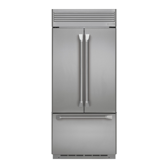
- Page 1 GE Appliances Technical Service Guide August 2016 GE Monogram® 36" Built-In French-Door Refrigerator ZIPS360NHSS ZIPP360NHSS ZIP360NH 31-9259 GE Appliances Louisville, Kentucky 40225...
-
Page 2: Safety Information
GE Appliances Technical Service Guide Copyright © 2016 All rights reserved. This service guide may not be reproduced in whole or in part in any form without written permission from GE Appliances. – 2 –... -
Page 3: Table Of Contents
Table of Contents Safety Information ..................................2 Table of Contents ..................................... 3 Safety Requirements ..................................6 Nomenclature ....................................7 Introduction ....................................... 8 Technical Data ....................................9 Operating Instructions ................................. 10 Temperature Controls ................................. 10 Changing Display Temperatures from °F to °C Installation ................10 Door Alarm .................................... - Page 4 Damper ...................................... 23 HMI (User Interface) ................................24 Freezer ........................................25 Freezer Interior Component Locator ........................... 25 Freezer Baskets ..................................26 Freezer Lighting ..................................26 Icemaker ....................................27 Evaporator Component Locator ............................ 30 Defrost Heater ..................................31 Safety Thermostat ................................31 Defrost System ....................................
- Page 5 Water Valve Assembly ................................ 45 Inverter Compressor................................46 Inverter ...................................... 46 Main Board ....................................47 Main Board Connector Locations ..........................48 Diagnostic Mode ....................................50 Schematic Diagram ..................................51 Monogram Refrigerator Warranty ............................52 Index ........................................53 – 5 –...
-
Page 6: Safety Requirements
Safety Requirements GE Factory Service Employees are required to use safety glasses with side shields, safety gloves and steel toe shoes for all repairs. Electrically Rated Glove and Steel Toed Work Boot Dyneema®Cut Resistant Dyneema® Cut Resistant Glove Glove Keeper... -
Page 7: Nomenclature
Nomenclature Z I P P 3 6 0 N H A S S Brand Handle Options Z - Monogram SS - Stainless case/handle Engineering Digit Installation 0 - 99 I - Built-in Model Year Configuration 2014 P - French Door Bottom Freezer Dispenser Door Panel D - Ice and water dispenser... -
Page 8: Introduction
Introduction Monogram introduces 36" Built In Freezer French Door Refrigerators. The refrigerators are available in three styles: European, Professional, and custom panel. All LED lighting illuminates the fresh food and freezer sections with crisp clear lighting throughout the interior. The French door design gives wide-open access to bins, shelves and drawers. The aluminum-trimmed glass bins and shelves allows convenient visible access to contents in the fresh food section. -
Page 9: Technical Data
Technical Data MONOGRAM - ZIP360NHA, ZIPP360NHASS, ZIPS360NHASS Electrical Shock Hazard REFRIGERATION SYSTEM WARNING Compressor 833 BTU/hr Death or serious injury can result from failure to follow these instructions. Minimum Compressor Capacity • Vacuum 22 inches • Disconnect power before servicing this product. Minimum Equalized Pressure •... -
Page 10: Operating Instructions
Operating Instructions Temperature Controls Changing Display Temperatures from °F to °C Installation The temperature display shows the actual temperature of the freezer and fresh food To change the temperature display between compartments. The actual temperature will vary Fahrenheit and Celsius, press Temp °C/°F. from the set temperature based on factors such as frequency of door opening, amount of food, defrost cycling and room temperature. -
Page 11: Installation
ATTENTION: Commonwealth of Massachusetts between 40 psi and 120 psi. Plumbing Code 248CMR shall be adhered to. Route 1/4 in. OD copper or GE SmartConnect™ Saddle valves are illegal and use is not permitted plastic tubing between the house cold water line in Massachusetts. -
Page 12: Anti-Tip Device
6. Align the straight section of the pin with the hole Anti-Tip Device from the underside of the rod. Push the pin up until it snaps into position. Pliers may be used. Tip Over Hazard! WARNING NOTE: The hair pin cotter must be vertical when this step is completed to ensure the “L”... -
Page 13: Level Refrigerator
4. Turn on the water to check for leaks. CAUTION GE SmartConnect™ Tubing: The rear leveling wheels and front leveling legs are limited to a maximum height adjustment of 1 inch. 3. Insert the molded end of the tubing into If the installation requires more than 84-1/2 inch the refrigerator connection. -
Page 14: Fresh Food Doors
Fresh Food Doors Door Alignment Adjust Door Swing Stand away from the refrigerator to inspect the door NOTE: This refrigerator has a 2-position door stop. alignment. When space does not allow the door to swing open fully to 130 degrees, change the door swing to a 90 Installation or the addition of heavy door panels degree opening. -
Page 15: Door Bins
Door Bins Fresh Food Doors Some door bins are adjustable and can be moved Fresh Food Door Removal up and down to meet storage needs. 1. Remove the switch cover. NOTE: The deeper door bins must be placed at the 2. -
Page 16: Vertical Mullion
Mullion Removal Vertical Mullion 1. Remove two T15 Torx screws at the top of the door securing the wire cover, then remove the cover. 2. Disconnect the mullion connector. NOTE: If removing the mullion to replace the door, proceed to step 4. 3. - Page 17 Mullion Reinstallation When reinstalling the mullion, ensure the mullion spring is seated in the recess of the door, as shown in the image below. – 17 –...
-
Page 18: Freezer Drawer
Freezer Drawer Drawer Closer Freezer Drawer Front Removal 1. Remove the lower freezer basket. The freezer drawer closer is mounted to the right • Lift straight up until the tabs on the sides front of the freezer liner, just below the main freezer disengage from the slots on the slide drawer slide assembly. -
Page 19: Main Drawer Slides
Main Drawer Slides The main freezer drawer slide assemblies are attached to the drawer front, and are mounted to the sides of the freezer interior with three T20 Torx screws per side. The slide must be extended to expose the front screw. The center and rear holes are slotted for adjustment to obtain proper sealing of the drawer gasket to the cabinet frame. -
Page 20: Fresh Food
Fresh Food 1. Fresh food door switches 6. Deli pan slides 2. Top mullion striker 7. Return air passage 3. Inlet air passages 8. Lower LED lighting 4. HMI assembly 9. Upper LED lighting 5. Vegetable pan slides 10. Fresh food thermistors –... -
Page 21: Shelves And Bins
Vegetable and Deli Glass Pan Cover Removal Shelves and Bins The glass shelves over the vegetable and deli pans Pan Removal may be removed for cleaning. 1. To remove the pan, pull out and then pull up on Pan Cover Removal pan. -
Page 22: Fresh Food
Middle slides can be changed without removing the Fresh Food middle bracket from the center shelf track. Drawer Slide Removal Four sets of nuts and bolts join the slides to the brackets. Each slide will rest on two locating pins Brackets secure both the upper and lower slides which aid installation of the new parts. -
Page 23: Damper
Upper and lower LED boards are mounted with two Damper Removal plastic retainer pins. LED boards can be removed by Remove the top light shield (see Fresh Food squeezing in on the sides of the pins, then pulling Lighting section). The LED harness will need to be down on the board and disconnecting the three pin unclipped from the LED housing prior to removing connector. -
Page 24: Hmi (User Interface)
HMI (User Interface) The HMI is located at the top of the fresh food section. Through the HMI, the consumer is able to change freezer and fresh food temperature settings, switch between Celsius and Fahrenheit, reset the HMI Removal 1. Remove the light shield. 2. -
Page 25: Freezer
Freezer Freezer Interior Component Locator 1. Freezer drawer closer 2. Freezer drawer switch and actuator 8. Icemaker electrical connector 3. Freezer drawer slides 9. Evaporator cover 4. Upper basket slides 10. Freezer LED lighting 5. Icemaker diverter 11. Freezer fan cover 6. -
Page 26: Freezer Baskets
Freezer Baskets Freezer Lighting Inside the freezer drawer is a wire slide-out freezer The freezer LED lighting is located at the top front basket. middle of the freezer compartment. It is covered by a translucent plastic lens. To remove the lens, press This basket can be pushed back so items on the in on the two tabs at the center and right then pull bottom of the freezer drawer can be reached. -
Page 27: Icemaker
Icemaker Mounting Screws Fill Cup Fill Tube Fill Tube Heater ON/OFF Lever Feeler Arm Electrical Connector A newly-installed refrigerator may take 12 to The ice bucket is conveniently located in the upper 24 hours to begin making ice. The icemaker will freezer basket. - Page 28 main board K3 relay by supplying 120 VAC to the isolation and water valves from connector J7 pin 3. If the defrost heater is on, the Fill Tube Heater relay will be on. After the Fill Tube Heater is on during defrost, the water valve relay will not be energized. The water valve will require input from the icemaker to energize the K3 relay.
- Page 29 Ice Diverter Evaporator Cover The ice diverter located just below the icemaker is to The freezer evaporator cover is located at the rear aid in retaining ice cubes in the bucket. The diverter of the freezer compartment. It is removable with the It is held in place by three Phillips screws.
-
Page 30: Evaporator Component Locator
Evaporator Component Locator 1. Fresh food air return 5. 140°F safety TCO 2. Defrost heater retainer clips 6. Freezer fan assembly 3. Defrost heater 7. Fresh food fan assembly 4. Evaporator thermistor See the section for more information on the freezer and fresh food fans. –... -
Page 31: Defrost Heater
Defrost Heater The defrost heater is a ceramic heater which has a resistance of 38 ohms and will receive 120 VAC from the main board during defrost. Diagnosing • J9 (red) - J7 pin 9 (orange) Note: Since the safety thermostat is also in line with the defrost heater, when the heater circuit is open from the main board it will be necessary to check at the heater terminals to determine if the heater or... -
Page 32: Defrost System
Defrost System Adaptive Defrost Adaptive Defrost (Pre-Chill Operation) Adaptive Defrost is a defrost system that adapts When the main control board determines that to a refrigerator’s surrounding environment and defrost is necessary, it will force the refrigerator into household usage. Unlike conventional defrost a continuous cool mode called pre-chill. -
Page 33: Cabinet Bottom
Cabinet Bottom Cabinet Bottom Component Locator 1. Rear roller adjustment 5. Defrost drain pan 2. Front leveling leg 6. Auxiliary condenser 3. Mobility assembly 7. Drain pan fan 4. Inlet water tube section for more information on the drain pan fan. Toe Kick Installation •... -
Page 34: Fresh Food Fan
Fresh Food Fan FF Air Duct Inside Wall The fresh food fan utilizes a 12 VDC motor to circulate freezer air into the fresh food compartment through the fresh food air duct. The fan is located above the right side of the evaporator and attached to the back wall of the freezer with two 1/4 in. -
Page 35: Freezer Fan
7. Separate the fan from the housing. Freezer Fan The freezer fan is a permanent magnet 4-pole, DC medium, and low. The speed of the fan is controlled by the voltage output from the main control board. Voltage output from the control board to the fan is 13.6 VDC;... -
Page 36: Condenser Fan
The freezer fan uses four wire connections: Condenser Fan • White Wire (DC Common) The condenser fan is a permanent magnet 4-pole, The white wire is the DC common wire used high, medium*, and low*. The speed of the fan is for testing. -
Page 37: Drain Pan Fan
7. Note the orientation and position of the fan Drain Pan Fan blade, then pull straight forward to remove it from the motor shaft. 8. Remove the two screws from the fan bracket to release the fan motor. 9. Disconnect the electrical connector and pull be uninstalled and the machine compartment top cover removed. - Page 38 Fan Speeds • Condenser Low/Med: 34.25% Duty Cycle 4 - 5 • Condenser High: 96.00% Duty 12 - 13 VDC • FZ Fan Low: 2143 RPM • FZ Fan Med: 2400 RPM • FZ Fan High: 6000 RPM (max) • FF Fan Low: 29.00% Duty Cycle 3.5 - 4.5 VDC •...
-
Page 39: Thermistors And Sensors
Thermistors and Sensors Ambient Thermistor Thermistors The ambient thermistor is located in the left side of thermistors to read the the machine compartment and mounted in front of temperatures inside and outside the refrigerator. To the humidity sensor with one Philips screw. test the thermistors, use the chart below. - Page 40 Fresh Food Thermistors Diagnosing The fresh food section has two thermistors (FF1 The freezer thermistor resistance can be checked on and FF2). Both thermistors are located behind the the J1 connector of the main board. left drawer. Two Philips screws hold the cover that •...
-
Page 41: Humidity Sensor
Humidity Sensor The humidity sensor is located in the left side of the machine compartment, on the bracket behind the ambient thermistor. The humidity sensor is energized as long as the refrigerator is powered up. The main board supplies the sensor with 5 VDC. Feedback from the sensor controls the vertical mullion heater, and can be read from the main board. -
Page 42: Cooling System
Cooling System Suction Line Suction Line Muffler Process Process Tube Tube Condenser Condenser *Inverter *Inverter Compressor Compressor Dryer Dryer Discharge Discharge **Capillary **Capillary **Suction Tube **Suction Tube Evaporator Evaporator **Condenser **Condenser Loop Loop Hot Wall Condenser Hot Wall Condenser *Approximate location of inverter *Approximate location of inverter Auxiliary Condenser Auxiliary Condenser... -
Page 43: Machine Compartment
Machine Compartment Cabinet Top Component Locator 1. Fresh Food Door Closures 8. Water Supply Tube 2. Actuator Arms 9. Icemaker supply line 3. Ambient Sensor 10. Main Board Enclosure 4. Humidity Sensor 11. Inverter 5. Filter Head Assembly 12. Compressor 6. -
Page 44: Water Filter Cartridge
4. Line up the arrow on the cartridge with the center of the holder. Do not push it up into the holder. system, GE recommends the use of GE branded 5. Slowly turn it to the right until the cartridge stops. It will rotate about 1/4 turn. -
Page 45: Water Valve Assembly
Filter Head Assembly Removal 6. Tip the bracket down to access the tubing connections on the valve assembly. 7. Push in on the collar and pull on the water line 2. Unclip the AC harness from the left of the to remove the head assembly. -
Page 46: Inverter Compressor
Inverter Removal Inverter Compressor The compressor is a reciprocating, variable speed, 4-pole type. It operates on 3-phase, 80 to 230 VAC within a range of 57 to 104 Hz. An inverter controls the speed of the compressor by frequency variation and by Pulse Width Modulation (PWM). -
Page 47: Main Board
3. Pull the enclosure out and swing the enclosure Main Board to the left. The main board controls all the functions of the refrigerator. The board is supplied with 120 VAC on J11 and will deliver AC and DC voltage to operating components. -
Page 48: Main Board Connector Locations
Main Board Connector Locations – 48 –... - Page 49 Main Board Connector Locations (continued) J1-1: Fresh food 1 thermistor input J7-1: 120 VAC output to icemaker J1-2: Fresh food 2 thermistor input J7-2: Icemaker Fill tube heater J1-3: Freezer thermistor input J7-3: 120 VAC output icemaker water valve J1-4: Evaporator thermistor input J7-4: Open J1-5: thermistors...
-
Page 50: Diagnostic Mode
Diagnostic Mode Enter the diagnostic mode by pressing both freezer temperature pads (plus and minus) and the refrigerator temperature pads (plus and minus) simultaneously. All four pads must be held for approximately three seconds. A blinking "0" in both displays indicate the refrigerator has entered diagnostic mode. Enter the appropriate display numbers as shown below and press any pad other than the temperature pads to activate that test mode. -
Page 51: Schematic Diagram
Schematic Diagram – 51 –... -
Page 52: Monogram Refrigerator Warranty
This warranty is extended to the original purchaser and any succeeding owner for products purchased for ordinary home use in the 48 mainland states, Hawaii, Washington, D.C. or Canada. If the product is located in an area where service by a GE Appliances Authorized Servicer is not available, you may be responsible for a trip charge or you may be required to bring the product to an Authorized GE Appliances Service location for service. -
Page 53: Index
Index ambient thermistor 41, 49 compressor 9, 32, 36, 46 Condenser 9, 36, 37, 38, 42, 43, 49 Condenser Fan 36, 37, 43 Defrost 9, 30, 32, 33, 49, 50 Defrost heater 30, 49 Diagnostic 50 Drain Pan Fan 37, 38 filter head 43, 45 Freezer Fan 29, 35, 37 Fresh Food Fan 34...