Table of Contents
Quick Links
SHARP
1. PRODUCTS OUTLINE
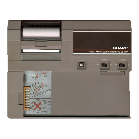
The CE-129P printer is an optional printer with the cassette
interface designed for use with the pocket computer models
EL-5500,
PC-1401 (EL-55001I).
5510), and PC-1430 (EL-5400)
2. WCIFICATIONS
Printer type:
Oot
used for the CE-125
Printing digit:
24 digits/line
Printing speed:
Paper feed speed:
Paper:
Power source:
Operation:
Power consumption:
Operating
temperature:
Dimensions:
Weight:
Accessories:
PC-1402, PC-1421
matrix
thermal
printer
(MTP-201), identical to the one
Approx. 0.8 line/second
(Printing
speed varies with the
number
of printing
digits per
line.]
Approx. 0.8 line/second
Thermal
paper
(heat
sensitive
paper), EA-1250P
18mm (23/32")
roll outer diameter (max.)
58mm (2-9/32") wide
6V::: (OC):
Heavy duty manganese battery,
AA
RG)
size
(or
x 4
AC:
local
voltage with AC adaptor
EA-23E (Option)
Heavy duty
manganese battery,
AA
R6,:
size
(or
Approx. 3,000 lines
UM-3: Approx. 2,000 lines
(Condition: 555555555555.
continuous
printing at an operat-
of lOD C ,
ing temperature
number
of printing
lines varies
with the type of battery or the
way of use.1
3.0W
D
C -
C (32° F -l04
F,
40
D
OD
x
x
198(W)
156(0)
34(H)mm
6-5132"(0)
7-25/32"(W) x
x
1-11/32"(H)
385g (0.85Ibs_1 (with batteries)
Dry
Hard case,
battery )( 4, Paper
roll
x 3,
Cassette
cable,
Operation manual
SHARP CORPORATION
SERVICE MANUAL
CODE:OOZCE129PSM/E
MODEL
3. TAPE RECORDER INTERFACING
METHOD
(EL-
CE· I 29P
Tepe R~order
I@!!!..
Grey
ptug
.nd
(tr.nsftr
eDU.liDnl
Cassette Tape Recorder
The following is a description of the minimum tape
der specifications
129P.
!lem
1. Recorder Type
2. Input Jack
3. Input lmepedance
is on
this
4_ Minimum Input Level
5. Output jack
6. Output impedance
7. Output level
8. Distortion
9. Wow and Flutter
and
10. Other
Do not sale !
C E-l29P
CE-129P
• Printer/Cassette
Interface
CE· 1 29P
I•• ;1!tI
I I I
---+
--
kpl ...
Grey pI...
I
..
!transfer
and
=<>troll
ClDUalionl
i
c.sette connec:tion cable
necessary
for interfacing with the CE-
Requirements
Any t&pe recorder, standard cassene
or micrCH:8ssette recorder, may
used in accordance
quiremenu outlined below.
The recorder should have a mini-
jack input labeled "MIC".
use the "AUX" jack.
The input jack should
input
impedance
OHM.)
Below 3mV or -50 dB.
Should be a minijack labeled "EXT.
(EXTemal speaker)", "MONITOR",
"EAR (EAR-phone)" or quivalent.
Should
below 10 OHM.
be
Should be above 1V (practical rnax-
imum output above 100 mW)
Should
within
be
range of 2 kHz through 4 kHz.
0.3% maximum (W.R.M.SI
Recorder motor should not fluctu-
ate
speed.
-
.
Tape recorder
+-BI
.. kplug
bemoll
contral)
Red plug
(racordingl
recor-
be
with the re-
Never
a low
be
(200
-
1,000
15% within a
------
Table of Contents

Related Manuals for Sharp CE-129P


Summary of Contents for Sharp CE-129P
-
Page 1: Service Manual
MODEL • Printer/Cassette Interface 3. TAPE RECORDER INTERFACING METHOD 1. PRODUCTS OUTLINE The CE-129P printer is an optional printer with the cassette interface designed for use with the pocket computer models EL-5500, PC-1401 (EL-55001I). PC-1402, PC-1421 (EL- 5510), and PC-1430 (EL-5400) 2. -
Page 2: Circuit Description
P21 P&3 4. CIRCUIT DESCRIPTION BuS)" Ooul The CE-129P has two microprocessors; the P-CPU (inside of CE-129P) by with data transfer is carried out with the POO P03 host CPU (M-CPU: inside of computer) and the prlnter SELI control PCU. - Page 3 C E-l29P 6. P-CPU (MPD75060515, 516 SIGNAL DESCRIPTION) C-MOS 1 chip 4 bit micro-computer Terminal Terminal Description Signal name Input/Output name System clock Oscillation frequency -- approx. 200 KHz System clock Power supply, OV reset input: when power supply is ON, reset operation. Input Min 30 Input/(Output)
-
Page 4: Service Cautions
C E-l29P 7. PCU (SC6994) SIGNAL DESCRIPTION - Oescription Pin No. Signal Name In/Out Select SEL2 Select SEl1 Power supply Notused BUSY Histl: chip select - - - - - - - - - Low: Non~lect Hi!#l to low transition: write Hi!#l: read Dm input... - Page 5 • Step 2_ A) After replacement has been made in same electronic Connect the EA-23E AC adaptor with the CE-129P after component parts inside the solid line. the TEST3 pad temperature came down to the room B) When service request is placed from the user claiming...
- Page 6 CE· 1 29P OFF CURRENT CHECK Operate the paper feed key when a computer is not 200: :8" connected to the CE-129P, and check if paper feed 210:LPRIHT Y!Y;CHRS 34;Y operation (ON,.OFF) is executed normally. 2. Supply -5.0V from stabilized power supply to Vp U$%&Y;CHR$ 39;Y()*+,...
-
Page 7: Circuit Diagram
C E-l29P 9. CIRCUIT DIAGRAM • · ..!. :> ..., ä l " w'· I> > Ö "" CI> > I' " ~~t~ I E" · ~ ID i:i! • > 'i::l ------r Do not sale ! - Page 8 ""'" • t~t- ,:/1 I I I I I 1 .>< "$ """"r" LL.>- -t;- ;:;: > >C JMt. "'" "' " 2 > a,lI) <1..., • Ö SI , .-!- "' > :8 ' . .-' E" L..;. .6-:,; ~ 10 •.
- Page 9 10. MAIN P.W.B ;; :ä '" ci ci ~ $ $ '" z ,_ ..~ • Do not sale !
- Page 10 C E-l29P Do not sale !
- Page 11 C E-l29P 11. SUB P.W.B ..• Do not sale ! -11-...
-
Page 12: Parts List & Guide
12. PARTS LIST & GUIDE l" "'-1 Do not sale ! _____ -12'~ .•... _ .._... - Page 13 11 - J BLO SGO 7363 8-105 S/NCEI29P ' . . ". ------------------------------ .." JI6 - 141085/106002000 SHARP CORPORATION Information Systems Group Quality & Reliability Control Center Yamatokoriyama, Nara 639-11, Japan ® 1985 August Printed in Japan -14- Do not sale !
- Page 14 C E-l29P Exteriors PART PRICE NO.1 PARTS CODE DES C R IP T ION RANK RANK MARK GCOVA Paper cover PCUT- Paper cutter panefX Dec. Dec. panel B Top cabinet ihield tape_ 'rinter cushion PCUSS _!_I K i-I rhermal printer unit CMTP-201) icrew (2X5) BG_I_N iub PWB unit...