HP MSR954 Series Installation Manual
Hide thumbs
Also See for MSR954 Series:
- Configuration manual (400 pages) ,
- Product end-of-life disassembly instructions (3 pages)
Table of Contents
Table of Contents

Related Manuals for HP MSR954 Series


Summary of Contents for HP MSR954 Series
- Page 1 HP MSR954 Routers Installation Guide Part number: Document version:...
- Page 2 The only warranties for HP products and services are set forth in the express warranty statements accompanying such products and services. Nothing herein should be construed as constituting an additional warranty.
-
Page 3: Table Of Contents
Contents Preparing for installation ············································································································································· 3 Safety recommendations ·················································································································································· 3 Safety symbols ·························································································································································· 3 General safety recommendations ··························································································································· 3 Electricity safety ························································································································································ 4 ESD prevention ························································································································································· 4 Examining the installation site ········································································································································· 4 Temperature and humidity ·······································································································································... - Page 4 JH298A ·································································································································································· 35 JH299A ·································································································································································· 35 LED description ······························································································································································· 35 Support and other resources ····································································································································· 38 Contacting HP ································································································································································ 38 Subscription service ·············································································································································· 38 Related information ························································································································································ 38 Documents ······························································································································································ 38 Websites ································································································································································· 38 ...
-
Page 5: Preparing For Installation
BJNGA-BB0039 IMPORTANT: For regulatory identification purposes, every MSR954 router is assigned a regulatory model number (RMN). These regulatory model numbers should not be confused with the marketing name HP MSR954 or the product code. Safety recommendations To avoid any equipment damage or bodily injury, read the following safety recommendations before installation. -
Page 6: Electricity Safety
Electricity safety Locate the external power switch in the room before installation. Shut off the power immediately if an accident occurs. Make sure the router is reliably grounded. Do not remove and install the chassis cover when the router is operating. ... -
Page 7: Cleanliness
Lasting low relative humidity can cause washer contraction and ESD and bring problems including loose captive screws and circuit failure. High temperature can accelerate the aging of insulation materials and significantly lower the reliability and lifespan of the router. Table 2 Temperature/humidity requirements in the equipment room Temperature Relative humidity... -
Page 8: Lightning Protection
Electromagnetic wave radiation. Common impedance (including the grounding system) coupling. To prevent EMI, perform the following tasks: If AC power is used, use a single-phase three-wire power receptacle with protection earth (PE) to filter interference from the power grid. Keep the router far away from radio transmitting stations, radar stations, and high-frequency ... -
Page 9: Pre-Installation Checklist
Pre-installation checklist Item Requirements There is a minimum clearance of 10 cm (3.9 in) around the air inlet and outlet vents. Ventilation An adequate ventilation system is available at the installation site. Temperature 0°C to 40°C (32°F to 104°F) Relative humidity 5% to 90% (noncondensing) Dust concentration ≤... -
Page 10: Installing The Router
Keep the tamper-proof seal on a mounting screw on the chassis cover intact, and if you want to open the chassis, contact HP for permission. Otherwise, HP shall not be liable for any consequence. Installation prerequisites You have read "Preparing for... -
Page 11: Installing The Router
Figure 3 Installation flowchart Installing the router Mounting the router on a workbench IMPORTANT: Make sure the workbench is clean, stable, and reliably grounded. Maintain a minimum clearance of 10 cm (3.9 in) around the router for heat dissipation. ... -
Page 12: Mounting The Router On A Wall
Figure 4 Mounting the router on a workbench Mounting the router on a wall Mark two screw hole locations on the wall. Make sure the two holes are 160 mm (6.30 in) horizontally apart. Drill holes with a minimum depth of 22 mm (0.87 in) in the marked locations. Use a hammer to tap an anchor into each hole until the anchor end is flush with the wall. -
Page 13: Installing The Router In A Rack
Figure 5 Wall-mounting the router ≥ 22 mm (0.87 in) ≥ 1.5 mm (0.06 in) Installing the router in a rack CAUTION: The mounting brackets can support only the weight of the router. Do not place objects on the router. To install the router in a rack: Use a mounting bracket to mark the cage nut installation holes in the front rack posts, as shown Figure... - Page 14 Figure 6 Marking cage nut installation holes Install the cage nuts, as shown in Figure Insert one ear of a cage nut into the marked installation hole. Use a flathead screwdriver to push another ear into the same hole. Figure 7 Installing cage nuts...
- Page 15 Attach mounting brackets to both sides of the router, as shown in Figure Figure 8 Attaching mounting brackets to the router Use M6 screws to attach the mounting brackets on the router to the front rack posts, as shown Figure Figure 9 Securing the router to the rack...
-
Page 16: Grounding The Router
Grounding the router CAUTION: Correctly connecting the grounding cable is crucial to lightning protection and EMI protection. When you install and use the router, first ground the router reliably. Ensure a minimum resistance of 5 ohms between the router and the ground. The router provides only a ring terminal. -
Page 17: Installing A 4G Sim Card
Figure 11 Grounding the router by burying a grounding conductor in the earth ground Installing a 4G SIM card CAUTION: Do not hot-swap a 4G SIM card. To avoid damaging the SIM card slot, do not use excessive force when installing a 4G SIM card. ... -
Page 18: Installing A Micro Sd Card
Installing a Micro SD card CAUTION: To avoid damaging the Micro SD card slot, do not use excessive force when you install a Micro SD card. To install a Micro SD card: Remove the screw on the Micro SD card slot cover and take off the cover. Insert the Micro SD card into the Micro SD card slot along the guide rails. -
Page 19: Installing A Wlan Antenna
Figure 14 Installing 4G antennas Installing a WLAN antenna Only the JH297A, JH298A, and JH299A routers support WLAN antennas. To install a WLAN antenna: Change the angle of the antenna orientation from vertical to horizontal. Attach the antenna to the WLAN antenna port on the router. Do not over-tighten the antenna to avoid damage. -
Page 20: Connecting Ethernet Interface Cables
Figure 16 Installing a GPS antenna Connecting Ethernet interface cables Connect one end of the cable to an Ethernet port on the router. Connect the other end of the cable to the Ethernet port on a host. Examine the port LEDs on the router. For more information about the LEDs, see "LED description."... - Page 21 To connect the console cable: Select a configuration terminal, which can be an ASCII terminal with an RS232 serial port or a PC. (A PC is more commonly used.) Connect the DB-9 connector (female) of the console cable to the RS-232 serial port on the configuration terminal and the RJ-45 connector to the console port of the router.
- Page 22 Figure 20 Setting the serial port used by the HyperTerminal connection Set Bits per second to 9600, Data bits to 8, Parity to None, Stop bits to 1, and Flow control to None, and click OK. NOTE: To restore the default settings, click Restore Defaults. Figure 21 Setting the serial port parameters...
- Page 23 Select File > Properties in the HyperTerminal window. Figure 22 HyperTerminal window On the Settings tab, set the emulation to VT100 or Auto Detect, and click OK. Figure 23 Setting the terminal emulation parameters...
-
Page 24: Connecting The Power Cord
Connecting the power cord Make sure the router is reliably grounded Connect one end of the AC power cord to the AC power receptacle on the router, and connect the other end to the AC power source. Figure 24 Connecting the power cord Verifying the installation After you complete the installation, verify the following information: ... -
Page 25: Observing The Startup Process
System is starting... Press Ctrl+D to access BASIC-BOOTWARE MENU... Booting Normal Extended BootWare The Extended BootWare is self-decompressing..Done. **************************************************************************** HP 95X BootWare, Version 1.43 **************************************************************************** Copyright (c) 2010-2015 Hewlett-Packard Development Company, L.P. Compiled Date : Jun 17 2014 CPU ID... -
Page 26: Power-On Check
Configuring basic settings for the router After the router is powered on for the first time, configure basic settings for the router. For more information, see HP MSR Router Series Configuration Guides(V7) and HP MSR Router Series Command References(V7). -
Page 27: Troubleshooting
Keep the tamper-proof seal on a mounting screw on the chassis cover intact, and if you want to open the chassis, contact HP for permission. Otherwise, HP shall not be liable for any consequence. Power module failure Symptom The router cannot be powered on and the LEDs on the front panel are off. -
Page 28: Garbled Display On The Configuration Terminal
Flow control—none. Emulation—VT100. Verify that the console cable is in good condition. If the problem persists, contact HP Support. Garbled display on the configuration terminal Symptom The configuration terminal has garbled display when the router is powered on. Solution... -
Page 29: Solution
Verify that the 4G antenna is correctly installed. Verify that the 3G/4G SIM card, card socket, and 4G antenna are in good condition. Verify that the network provided by NSP is running correctly. If the problem persists, contact HP Support. Restoring the factory settings Scenario 1 Symptom When you replace the router, the router password is lost. -
Page 30: Reset Button Usage Guidelines
Solution Press the Reset button for a short time to reboot the router. Reset button usage guidelines The router provides the Reset button. You can use the button to reboot the system or restore the factory settings. Press the Reset button for a short time to reboot the router. Press the Reset button for more than 4 seconds to reboot the router and restore the factory settings. -
Page 31: Appendix A Chassis Views And Technical Specifications
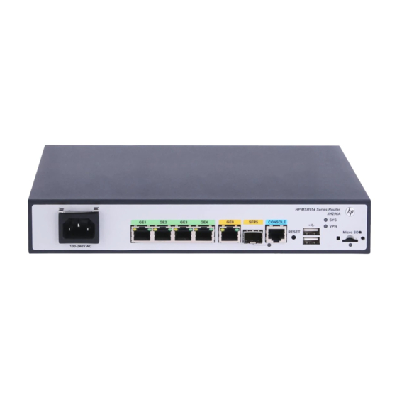
Appendix A Chassis views and technical specifications Chassis views The figures in this appendix are for illustration only. JH296A Figure 25 Front view (1) AC power receptacle (2) Gigabit Ethernet LAN ports (3) Gigabit Ethernet WAN port (GE0) (GE1 to GE4) (4) Gigabit fiber port (SFP5) (5) Console port (6) USB port... -
Page 32: Jh297A
JH297A Figure 27 Front view (1) AC power receptacle (2) Gigabit Ethernet LAN ports (3) Gigabit Ethernet WAN port (GE0) (GE1 to GE4) (4) Gigabit fiber port (SFP5) (5) Console port (6) USB port (7) Micro SD card slot (8) USB port (9) Reset button (RESET) Figure 28 Rear view (1) Grounding screw... -
Page 33: Jh299A
Figure 30 Rear view (1) Grounding screw (2) LTE antenna port 1 (3) 2.4G WLAN antenna port (4) 4G SIM card slot (5) GPS antenna port (6) 2.4G WLAN antenna port (7) LTE antenna port 2 JH299A Figure 31 Front view (1) AC power receptacle (2) Gigabit Ethernet LAN ports (3) Gigabit Ethernet WAN port (GE0) -
Page 34: Technical Specifications
Technical specifications Table 5 Router specifications Item JH296A JH297A JH298A JH299A Console port USB port GE WAN port GE SFP port GE LAN port Memory 1 GB DDR III 1 GB DDR III 1 GB DDR III 1 GB DDR III Flash 256 MB 256 MB... - Page 35 Table 7 WLAN antenna specifications Item Specification Frequency range 2.4 to 2.5 GHz Voltage standing wave ratio 1.92:1 (VSWR) Input impedance 50 ohms Gain 2 dBi Max power Input port RSMA Length 115 mm (4.53 in) Color Black Weight 25 g (0.88 oz ) Operating temperature –10°C to +60°C (14°F to 140°F)
-
Page 36: Appendix B Leds
Appendix B LEDs LEDs JH296A Figure 33 Front panel LEDs (1) GE port yellow LED (2) GE port green LED (3) System status LED (SYS) (4) Micro SD card LED (5) VPN status LED (6) SFP port LED JH297A Figure 34 Front panel LEDs (1) GE port yellow LED (2) GE port green LED (3) System status LED (SYS) -
Page 37: Jh298A
JH298A Figure 35 Front panel LEDs (1) GE port yellow LED (2) GE port green LED (3) System status LED (SYS) (4) VPN status LED (5) Micro SD card LED (6) LTE LED (7) 2.4G WLAN LED (8) SFP port LED JH299A Figure 36 Front panel LEDs (1) GE port yellow LED... - Page 38 Status Description Data is being received or transmitted at Flashing yellow 10/100 Mbps No 10/100 Mbps link is present. Steady green The SDRAM is performing self-test. The system software image is being copied Flashing green (8 Hz) and decompressed. Comware has started with the configuration Flashing green (1 Hz) file and the router has booted up.
- Page 39 Status Description Data is being received or transmitted at Flashing yellow 10/100 Mbps. No link is present.
-
Page 40: Support And Other Resources
After registering, you will receive email notification of product enhancements, new driver versions, firmware updates, and other product resources. Related information Documents To find related documents, browse to the Manuals page of the HP Business Support Center website: http://www.hp.com/support/manuals For related documentation, navigate to the Networking section, and select a networking ... -
Page 41: Conventions
HP Education http://www.hp.com/learn Conventions This section describes the conventions used in this documentation set. Command conventions Convention Description Boldface Bold text represents commands and keywords that you enter literally as shown. Italic Italic text represents arguments that you replace with actual values. - Page 42 Network topology icons Represents a generic network device, such as a router, switch, or firewall. Represents a routing-capable device, such as a router or Layer 3 switch. Represents a generic switch, such as a Layer 2 or Layer 3 switch, or a router that supports Layer 2 forwarding and other Layer 2 features.
-
Page 43: Index
Index Numerics dust (installation site), 4G antenna technical specifications, electrical connecting power cord, grounding router with buried grounding conductor, troubleshooting power supply failure, grounding router with grounding strip, accessories (installation), grounding the router, Appendix powering on the router, A chassis views and technical specifications, electricity electrical cooling requirements, B LEDs,... - Page 44 hardware technical specifications, 34, chassis cooling and ventilation, lightning grounding router with buried grounding protection, conductor, grounding router with grounding strip, mounting grounding the router, router on workbench, installation flowchart, installing 4G SIM card, installing WLAN antenna, network management router installation, 8, router installation, 8, router wall installation, troubleshooting router installation,...
- Page 45 startup process, troubleshooting garbled display, troubleshooting 3G/4G antenna failure, tools (installation), troubleshooting 3G/4G SIM card and troubleshooting 3G/4G antenna failures, 3G/4G antenna failure, troubleshooting 3G/4G SIM card failure, 3G/4G SIM card failure, troubleshooting garbled terminal display, garbled terminal display, troubleshooting no response from serial port, no response from serial port, power supply failure, troubleshooting power supply failure,...