Allen-Bradley 1747-SN User Manual
Remote i/o scanner
Hide thumbs
Also See for 1747-SN:
- Installation instructions manual (12 pages) ,
- Installation instructions manual (13 pages)
Table of Contents
Quick Links
Table of Contents

Related Manuals for Allen-Bradley 1747-SN

Summary of Contents for Allen-Bradley 1747-SN
- Page 1 Allen Bradley User Remote I/O Scanner Manual (Cat. No. 1747 SN)
- Page 2 PLC is a registered trademark of the Allen-Bradley Company, Inc. SLC, SLC 500, SLC 5/01, SLC 5/02, SLC 5/03, SLC 5/04, MicroLogix, PanelView, RediPANEL, Dataliner, PLC-5/15, PLC-5/12, PLC-5/25, PLC-5/30, PLC-5/40, PLC-5/60 are trademarks of Allen-Bradley Company, Inc.
-
Page 3: Preface
If you do not, contact your local Allen-Bradley representative for information on available training courses before using this product. If using Advanced Programming Software (APS), we recommend that you review The APS Quick Start for New Users, Publication 9399-APSQS, before you begin. -
Page 4: Table Of Contents
Contains blank worksheets for you to use when Appendix C Worksheets configuring the scanner's I/O images. Related Documentation The following documents contain additional information concerning Allen-Bradley SLC and PLC products. To obtain a copy, contact your local Allen-Bradley office or distributor. Publication 1747 6.6 - July 1996... - Page 5 Preface P–3 Document Read This Document Number An overview of the SLC 500 family of products SLC 500 System Overview 1747 2.30 A description on how to install and use your Modular SLC 500 Installation & Operation Manual for Modular 1747 6.2 programmable controller Hardware Style Programmable Controllers...
- Page 6 Technical Product Assistance If you need to contact Allen-Bradley for technical assistance, please review the information in the Troubleshooting chapter first. Then call your local Allen-Bradley representative. Your Questions or Comments on this Manual If you find a problem with this manual, please notify us of it on the enclosed Publication Problem Report.
- Page 7 Summary of Changes Summary of Changes The information below summarizes the changes to this manual since the last printing in February 1995. To help you find new information and updated information in this release of the manual, we have included change bars as shown to the right of this paragraph.
-
Page 8: Preface
Table of Contents Summary of Changes ......New Information ........Preface . -
Page 9: Quick Start For Experienced Users
Table of Contents Quick Start for Experienced Users ....Required Tools and Equipment ......Procedures . -
Page 10: Rio Block Transfer
Table of Contents General Communication Status - Enable Device Fault Bit ..4-21 General Communication Status - Communication Attempted Bit 4-22 RIO Baud Rate Status ......4-22 Logical Device Starting Address Status . -
Page 11: Troubleshooting
Table of Contents Block Transfer Read Control Logic Example ....5-23 Block Transfer Write Control Logic Example ....5-25 Directional Continuous Block Transfer Example . - Page 12 Table of Contents Determining TSNo-bt ....... Determining Tbtx ........Example Discrete I/O Throughput with Block Transfers Present Block Transfer Throughput .
-
Page 13: Overview
I/O scanner features compatible network devices System Overview The Remote I/O (RIO) scanner, Catalog Number 1747-SN, is the remote I/O scanner for the SLC 500. It enables communication between an SLC processor (SLC 5/02 or later) and remotely located (3,048 meters [10,000 feet] maximum) 1746 I/O chassis and other RIO compatible Allen-Bradley operator interface and control devices. - Page 14 1–2 Overview The scanner can be configured for and transfer a maximum of 4 logical racks of discrete data on the RIO link. The scanner provides discrete I/O and block (Series B or later) transfers. Configurations allowed are any combination of quarter, half, three quarter, or full logical rack devices.
-
Page 15: Scanner I/O Image Division
Overview 1–3 Scanner I/O Image Division The scanner allows each adapter to use a fixed amount (user defined) of the scanner’s input and output image. Part of the SLC processor’s image is used by local I/O, the other portion is used by the scanner for remote I/O. -
Page 16: How The Scanner Scans Remote I/O
1–4 Overview How the Scanner Scans The scanner communicates with each logical device in a sequential Remote I/O fashion. First, the scanner initiates communication with a device by sending output data to the device. The device then responds by sending its input data back to the scanner, as illustrated below. You refer to this exchange as a discrete I/O transfer. -
Page 17: Slc And Scanner Asynchronous Operation
Overview 1–5 SLC and Scanner Asynchronous Operation The SLC processor scan and RIO scanner scan are independent (asynchronous) of each other. The SLC processor reads the scanner input image file during its input scan and writes the output image file to the scanner during its output scan. -
Page 18: How The Scanner Interacts With Adapters
1–6 Overview How the Scanner Interacts The scanner’s function is to continuously scan the adapters on the with Adapters RIO link in a consecutive manner. This scan consists of one or more RIO discrete transfers to each adapter on the RIO link. RIO discrete transfers consist of the scanner sending output image data and communication commands to the adapter that instruct the adapter on how to control its output. -
Page 19: Scanner I/O Image Concepts
Overview 1–7 Scanner I/O Image The scanner’s I/O image consists of RIO logical racks and I/O Concepts groups. A full RIO logical rack consists of eight input image and eight output image words. (A word consists of 16 bits of data.) Each word within an RIO logical rack is assigned an I/O group number from 0 to 7. -
Page 20: Example Scanner I/O Image
1–8 Overview Example Scanner I/O Image The illustrations below show a scanner’s input image of 4 RIO link devices. SLC 5/02 or Later Processor Scanner Device 1 Device 2 Device 3 Device 4 Full Logical Rack Three Quarter Logical Half Logical Rack Quarter Logical Rack Device Rack Device... -
Page 21: Transferring Data With Rio Discrete And Block Transfers
RIO link devices have extended node capability. (Refer to the Compatible Devices table at the end of this chapter, or to the specifications of your device.) The 1747-SN Series B Scanner has extended node capability. However, the smallest logical rack division is 1/4 logical rack and the scanner image size is 4 logical racks. -
Page 22: Complementary I/O
1–10 Overview Complementary I/O Complementary I/O is very useful when portions of your input and output images are unused because it allows the images of two adapters to overlap each other in the scanner’s I/O image. To use complementary I/O, the I/O image from one adapter must be the mirror (complement) of the other. -
Page 23: Guidelines For Configuring Complementary I/O
Overview 1–11 ATTENTION: If the logical rack numbers are not properly assigned, unpredictable operation of both ASB modules results. No ASB module errors occur. Refer to your ASB module user manual for specific information on setting the address of the complementary chassis. -
Page 24: Complementary I/O: Placing Modules With 2 Slot Addressing
1–12 Overview Complementary I/O: Placing Modules with 2 Slot Addressing The figures below illustrate a possible module placement to configure complementary I/O using 2-slot addressing. Example 1 Example 2 Outputs in the complementary chassis would use the same bits in the output image table as the outputs in the primary chassis. -
Page 25: Complementary I/O: Placing Modules With 1 Slot Addressing
Overview 1–13 Complementary I/O: Placing Modules with 1 Slot Addressing The figure below illustrates a possible module placement to configure complementary I/O using 1-slot addressing. Example 1 Example 2 I = Input Module (8 or 16 point) O = Output Module (8 or 16 point) BT = Block Transfer Module 1 = Output modules use the same output image table bits. -
Page 26: Complementary I/O: Placing Modules With 1/2 Slot Addressing
1–14 Overview Complementary I/O: Placing Modules with 1/2 Slot Addressing The figure below illustrates a possible module placement to configure complementary I/O using 1-slot addressing. Example 1 Example 2 I = Input Module (8 , 16 , or 32 point) O = Output Module (8 , 16 , or 32 point) BT = Block Transfer Module 1 = Output modules use the same output image table bits. -
Page 27: Summary For Placing Modules Used In Complementary I/O
Overview 1–15 Summary for Placing Modules Used In Complementary I/O Discrete Modules Addressing Method Types of Modules used Placement Install input modules opposite output modules, 2 slot 8 point and output modules opposite input modules. 1 slot 8 point, 16 point 1/2 slot 8 point, 16 point, 32 point If an input module resides in either slot, associated with a logical group, of the primary chassis, an... - Page 28 1–16 Overview I = Input Module = Output Module Slot Slot Slot Pair Slot Pair Complementary Chassis Primary Chassis Primary Chassis Configured As: Complementary Chassis Configured As: Logical Rack Number Logical Rack Number 8 (decimal) Logical Group Number Logical Group Number Image Size (logical groups) Image Size (logical groups) Addressing Mode...
-
Page 29: Complementary I/O Application Considerations
Overview 1–17 Complementary I/O Application Considerations If you configure a complementary device to use more I/O image space than an associated primary device, then block transfers can only be performed to locations in the complementary device that have associated I/O image space in the primary device. For example, if a primary device is 1/2 logical rack and a complementary device is a full logical rack, block transfers can be performed only in the first 1/2 logical rack of the complementary device. -
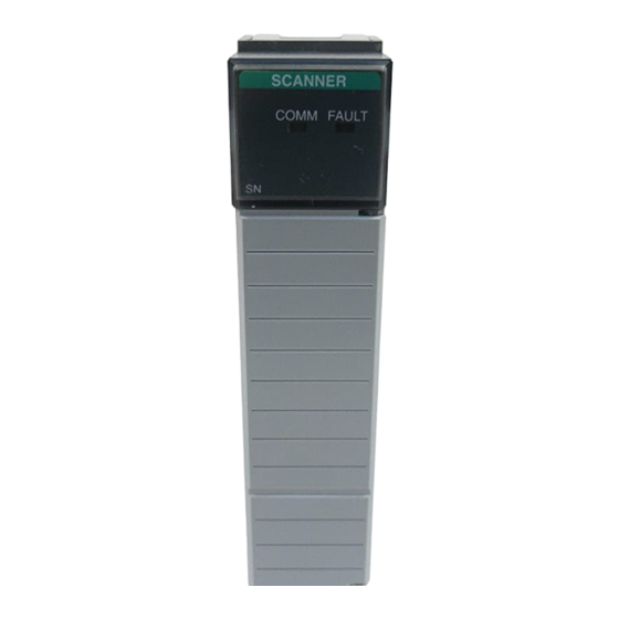
Page 30: Hardware Features
USER'S MANUAL. Î Î Î Î LINE 1 SHIELD Î Î Î Î Î Î LINE 2 1747-SN Table 2.A Hardware Features Status LEDs Displays normal communication and fault status Front Label Allows user to record configured baud rate RIO Link Connector... -
Page 31: Baud Rate Dip Switch
The COMM LED status information is valid only when the FAULT LED is off. RIO Link Connector This 3-pin male connector connects the scanner to the RIO link. The Allen-Bradley repair part number is 1746-RT29. Publication 1747 6.6 - July 1996... -
Page 32: Compatible Devices
1–20 Overview Compatible Devices Catalog Device Comments Number 1785 LT/x PLC 5/15 (in adapter mode) 1785 LT2 PLC 5/25 (in adapter mode) 1785 LT3 PLC 5/12 (in adapter mode) 1785 L30x PLC 5/30 (in adapter mode) 1785 L40x PLC 5/40 (in adapter mode) 1785 L60x PLC 5/60... -
Page 33: Quick Start For Experienced Users
Have the following tools and equipment ready: Equipment medium blade screwdriver programming equipment (All programming examples shown in this manual demonstrate the use of Allen-Bradley’s Advanced Programming Software [APS] for personal computers.) termination kit (package of resistors and ring lug included with the scanner) -
Page 34: Procedures
2–2 Quick Start for Experienced Users Procedures Check the contents of the shipping box. Reference Unpack the module making sure that the contents include: RIO Scanner (Catalog Number 1747 SN) termination kit user manual (Publication 1747 6.6) If the contents are incomplete, call your local Allen Bradley representative for assistance. Ensure your chassis supports placement of the 1747 SN module. - Page 35 Quick Start for Experienced Users 2–3 Insert the 1747 SN module into the chassis. Reference (Chapter 3) (Installation and ATTENTION: Never install, remove, or wire Wiring) modules with power applied to the chassis or devices wired to the module. Make sure system power is off; then insert the scanner module into your 1746 chassis. In this example procedure, local slot 1 is selected.
- Page 36 2–4 Quick Start for Experienced Users Configure the system. Reference Chapter 4 Set up your system I/O configuration for the particular slot in which you installed the scanner (slot 1 in (Configuration and this example). If using APS software, select the 1747 scanner from the list of modules. If it is not Programming) listed in your software version, select Other and enter the scanner input module ID code (13608) at the prompt on the I/O configuration display.
- Page 37 Quick Start for Experienced Users 2–5 Set the M0-M1 and G file sizes. Reference Chapter 4 Using the Specialty I/O Configuration menu, set the M1 and M0 file sizes to 32 words (48 words if (Configuration and Programming) using complementary I/O). (32 words is the minimum required for operation.) If you do not set the M1 and M0 file sizes to at least 32 words the programming device will not allow you to access the M Chapter 5 files in the SLC control program.
-
Page 38: Installation And Wiring
Chapter Installation and Wiring This chapter contains the information necessary to: select the baud rate insert the scanner into the SLC chassis wire the RIO link power up the scanner Compliance to European If this product has the CE mark it is approved for installation within Union Directives the European Union and EEA regions. -
Page 39: Baud Rate Selection
3–2 Installation and Wiring Baud Rate Selection Below are supported baud rates and switch positions: Baud Rate DIP Switch Position Switch 1 Switch 2 57.6K baud 115.2K baud 230.4K baud 230.4K baud The figure below shows the location of the DIP switches on the scanner. -
Page 40: Scanner Installation
Installation and Wiring 3–3 Scanner Installation Installation procedures for this module are the same as for any other discrete I/O or specialty module. Refer to the illustration on page 3–4 to identify chassis and module components listed in the procedures below. ATTENTION: Disconnect system power before attempting to install, remove, or wire the scanner. -
Page 41: Removal
3–4 Installation and Wiring Module Release Card Guide . . . Cable Tie Removal 1. Disconnect power. 2. Remove all cabling. 3. Press the releases at the top and bottom of the module and slide the module out of the chassis slot. 4. - Page 42 Installation and Wiring 3–5 Maximum Cable Distance Baud Rate Resistor Size (Belden 9463) 57.6K baud 3048 meters (10,000 feet) Using Extended Node Using Extended Node 1/2 Watt 1/2 Watt 115.2K baud 1524 meters (5,000 feet) Capability Capability Brown Green Brown Gold Brown-Green-Brown-Gold 230.4K baud 762 meters (2,500 feet)
-
Page 43: Start Up
3–6 Installation and Wiring Start Up The following steps will assist you in the start up of your RIO system. 1. Apply power to your SLC processor. If you powered down with the SLC processor in Program, Test, or Fault mode, you will have to place your processor in Run mode. -
Page 44: Scanner Operation
Installation and Wiring 3–7 Scanner Operation Below is a description of the scanner’s operation at power up, run mode, and when changing from run mode to program or test mode. At Power Up At power up, the the scanner’s communication LED (green LED) is off until the SLC is changed to Run or Test mode. -
Page 45: Status Leds
3–8 Installation and Wiring Status LEDs The scanner has two LEDs that indicate its operating status, FAULT and COMM. The FAULT LED indicates the scanner’s overall status. The COMM LED indicates the RIO link communication status. The FAULT LED is off whenever the scanner is configured and operating properly. -
Page 46: Scanner Configuration And Programming
Chapter Scanner Configuration and Programming This chapter contains information necessary to: understand remote I/O image files understand RIO configuration using G files control and view RIO devices using the M0 and M1 files understand slot addressing quickly configure the RIO Scanner Understanding Remote The SLC system allows you to assign up to 32 words of input and Input and Output Image... - Page 47 Logical Rack 3 Group 7 Word 31 Bit Number (octal) The 1747-SN Scanner’s I/O image structure is described below: The I/O image file consists of four logical racks (numbered 0,1,2, and 3) of input image and four logical racks of output image.
-
Page 48: Rio Configuration Using G Files
Scanner Configuration and Programming 4–3 RIO Configuration Using G When you program your SLC system you use the G file to configure Files the scanner’s I/O image file. Your scanner’s G file configuration is based on the devices that you have on the RIO link. G file configuration consists of setting logical device starting addresses and the logical device image size of each physical device/adapter with which the scanner communicates. - Page 49 4–4 Scanner Configuration and Programming Word 3, Complementary Logical Device Address – specifies the logical starting address of each complementary RIO link device. The logical address consists of the logical rack number (8, 9, 10, or 11 because a complementary device is always 8 above its primary) and starting logical group (0, 2, 4, or 6).
-
Page 50: Rules For Configuring The Scanner
Scanner Configuration and Programming 4–5 Rules for Configuring the Scanner General The smallest portion of the scanner’s I/O image that can be allocated to a single RIO device is two logical groups (1/4 logical rack). If a device is configured in word 1, there must be image allocated to it in word 2. -
Page 51: Example G File Showing Primary And Complementary Device Configurations
4–6 Scanner Configuration and Programming Example G File Showing Primary and Complementary Device Configurations In the example that follows we configured the scanner to communicate with primary and complementary devices. These are the device addresses and image sizes: Logical Racks 0/8, Logical Group 2 contain a primary 3/4 logical rack device, and a complementary 3/4 logical rack device. -
Page 52: Illegal Configuration Examples
Scanner Configuration and Programming 4–7 Illegal Configuration Examples Having a primary device configured at Logical Rack 1, Logical Group 2 (bit 5) would be illegal since this image space is already being used by a complementary device. Having a complementary device configured at Logical Rack 10, Logical Group 2 (bit 9) would also be illegal since this image space is already being used by a primary device. -
Page 53: Example Scanner Input Image Of The Primary Devices
4–8 Scanner Configuration and Programming Example Scanner Input Image of the Primary Devices Below are the primary device addresses and sizes. The following page contains complementary device addresses and sizes. Device 1 – starting at Logical Rack 0, Logical Group 2 is a primary 3/4 logical rack device. -
Page 54: Example Scanner Input Image Of The Complementary Devices
Scanner Configuration and Programming 4–9 Example Scanner Input Image of the Complementary Devices Below are the complementary device addresses and sizes. The previous page contains primary device addresses and sizes. Device 6 – starting at Logical Rack 8, Logical Group 2 is a complementary 3/4 logical rack device. -
Page 55: Considerations When Configuring Remote I/O
4–10 Scanner Configuration and Programming Considerations When The following sections contain information that you must understand Configuring Remote I/O before you configure your scanner’s G file. G File Considerations You can only change the RIO configuration by modifying the G file while offline in your program file. -
Page 56: Creating More Than One Logical Rack Device
Scanner Configuration and Programming 4–11 Crossing Logical Rack Boundaries - Example 1 Crossing Logical Rack Boundaries - Example 2 Scanner Input or Output Image Scanner Input or Output Image Bit Number (Decimal) Bit Number (Decimal) Group 0 Group 0 Group 1 Group 1 Group 2 Group 2... -
Page 57: Understanding M Files
4–12 Scanner Configuration and Programming Understanding M Files M Files Overview The scanner provides RIO device control and status information through the M0 and M1 files. The M0 file is a control file. The M1 file is a status file The SLC processor does not automatically update M file data during the end of the program scan as it does I/O scans. - Page 58 Scanner Configuration and Programming 4–13 Rung 2:0 To decrease program scan time, copy the first four words of the M1 File to a binary file and use these addresses throughout the program to access block transfer done, error, data, etc. information without interrupting the program scan many times.
-
Page 59: M0 Control File Description
M0 file until a full program scan occurs (after entering Run mode). This allows you to change the M file settings before they take effect. Important: The 1747-SN RIO Scanner does not use M0 words 0 – 7. M0 (Control) File - RIO Device Control Words Bit Number Device... -
Page 60: M0 File - Rio Device Inhibit Control
= slot number of the SLC rack containing the scanner x = not used/defined Example of Device Inhibit Control The 1747-SN Scanner inhibits (sets to 1) the bits in M0:e.8 through M0:e.11 (by default) wherever there are no configured devices present. The illustration below compares the configured devices (G file word 2) to the groups that the scanner automatically inhibits. -
Page 61: M0 File - Rio Device Reset Control
4–16 Scanner Configuration and Programming M0 File - RIO Device Reset Control M0 Words 16 through 19 – you use these words to command a reset (0) of RIO device outputs when the SLC processor is in Run or Test mode. This allows you to selectively reset logical device outputs based on a previous condition(s) that you defined. -
Page 62: M0 File - Remote Output Reset Control
Scanner Configuration and Programming 4–17 M0 File - Remote Output Reset Control M0 Words 24 through 27 – you use these words to command a logical device to reset all of its outputs when the SLC processor leaves the Run mode and enters the Test, Program, or Fault mode (regardless of the device’s Hold Last State setting). -
Page 63: Example Of Remote Output Reset Control
4–18 Scanner Configuration and Programming Example of Remote Output Reset Control By default the scanner sets the bits in M0:e.24 through M0:e.27 to 1 wherever there are configured devices present. This commands all devices’ outputs to reset regardless of their Hold Last State switch. The application program can remove commanded reset of devices by resetting bits to 0. -
Page 64: Device Reset And Remote Output Reset Considerations
Scanner Configuration and Programming 4–19 Device Reset and Remote The 1747-SN Scanner Device Reset words (M0:e.16 to M0:e.19) and Output Reset the Remote Output Reset words (M0:e.24 to M0:e.27) operate in Considerations conjunction with each RIO device to determine the state of that RIO device’s outputs. - Page 65 4–20 Scanner Configuration and Programming Example 1 – When powering up into Run mode, the scanner, by default, resets the appropriate bit in the Device Reset word to 0. The appropriate bit in the Remote Output Reset word is set to 1. As a result, the RIO link device outputs reflect the scanner’s output image.
-
Page 66: M1 Status File Description
Scanner Configuration and Programming 4–21 M1 Status File Description M1 file words 0 through 47 contain the status of all devices on the scanner’s RIO link. M1 is a read only file; do not write to this file. Words 0–47 of the M1 file provide the following information: Word 0 (M1:e.0) –... -
Page 67: General Communication Status - Communication Attempted Bit
4–22 Scanner Configuration and Programming General Communication Status - Communication Attempted Bit Word 0, bit 1 – is the Communications Attempted status bit. When RIO communication has been attempted with all configured devices, this bit is set to 1. There are no further transitions of this bit until a processor change of state occurs (i.e., Program mode to Run mode or Test mode, or Test mode to Run mode). -
Page 68: Logical Device Starting Address Status
Scanner Configuration and Programming 4–23 Logical Device Starting Address Status Word 8 – provides status/feedback of the logical device starting addresses you configured in word 1 of the G file (primary/normal logical devices). Writing to M1 file word 8 will not alter the contents of the G file. -
Page 69: Logical Device Image Size Status
4–24 Scanner Configuration and Programming Logical Device Image Size Status Word 9 – provides status/feedback of the logical device image size you configure in word 2 of the G file (primary/normal devices). A bit set to 1 shows the logical image size of each logical device. Writing to word M1 file word 9 will not alter the contents of the G file. - Page 70 Scanner Configuration and Programming 4–25 M1 (Status) File - Word 10 Bit Number (decimal) RIO Rack 3 RIO Rack 2 RIO Rack 1 RIO Rack 0 Starting Group Starting Group Starting Group Starting Group M1 File Primary Logical Device Address, Word 8 M1:e.8 Primary Logical Image Size, Word 9 M1:e.9...
-
Page 71: Logical Device Fault Status
4–26 Scanner Configuration and Programming Logical Device Fault Status Words 12 through 15, bits 0 to 7 – indicate the device fault status for logical racks 0, 1, 2, 3, 8, 9, 10, and 11. Bits 0 through 3 are for primary/normal devices and bits 4 through 7 are for complementary devices. -
Page 72: Rio Status Example
Scanner Configuration and Programming 4–27 RIO Status Example The following example illustrates an M1 status file example. It shows a typical M1 file and the G file used to configure the scanner. There are no inhibited devices specified in the M0 file (not shown). Notice that: M1:e.8 is an image of word 1 (primary/normal logical device address) of the G file. - Page 73 4–28 Scanner Configuration and Programming M1 (Status) File Complementary Bit Number (decimal) M1 File Status Word, Word 0 M1:e.0 Baud Rate, Word 2 M1:e.2 RIO Logical RIO Logical RIO Logical RIO Logical Rack 11 Rack 10 Rack 9 Rack 8 Complementary Device Starting Address, Word 3 M1:e.3 Complementary Device Image Size, Word 4...
-
Page 74: Rio Communication Retry Counter (M1:E.16 47)
Scanner Configuration and Programming 4–29 RIO Communication Retry M1 File Status Words 16 through 47 – indicate how many RIO Counter (M1:e.16 47) communication retries the scanner makes to each adapter on the RIO link if communication problems occur. Each word (16–47) contains a retry counter for each configured quarter logical rack (words 16–31 are for primary logical racks, 0–3, and 32–47 are for complementary racks, 8–11). - Page 75 4–30 Scanner Configuration and Programming M1:e.20 – communication retry counter for RIO logical rack 1, group 0 M1:e.21 – not used in this example M1:e.22 – not used in this example M1:e.23 – not used in this example M1:e.24 – not used in this example M1:e.25 –...
-
Page 76: Understanding Slot Addressing
Scanner Configuration and Programming 4–31 Understanding Slot This section provides information about: Addressing 2-slot addressing 1-slot addressing 1/2-slot addressing Understanding slot addressing is critical to most efficiently allocate your scanner’s I/O image files. Slot addressing refers to how each remote chassis slot is assigned a specific amount of the I/O image. -
Page 77: Slc/Scanner Configuration
4–32 Scanner Configuration and Programming SLC/Scanner Your SLC processor can be programmed with an HHT (Hand-Held Configuration Terminal) or APS (Advanced Programming Software). Although the configuration steps are similar, they are not identical. Therefore, the following basic steps are provided. For specific instructions, refer to the user manual included with your programming device. -
Page 78: Rio Block Transfer
RIO Block Transfer is a data transfer mechanism that allows you to control the transfer of up to 64 words of data to or from a remote device over the Allen-Bradley RIO link. A Block Transfer Read (BTR) is used when a remote device transfers data to the SLC. A Block Transfer Write (BTW) is used when an SLC processor writes data to a remote device. - Page 79 5–2 RIO Block Transfer RIO Block Transfer Theory of Operation - Path of a Block Transfer Refer to the diagrams on the following pages for more details on BTR and BTW sequence of Chassis Backplane operation. É É É É É É É É...
- Page 80 RIO Block Transfer 5–3 RIO Block Transfer Theory of Operation - Block Transfer Read (BTR) In this example, Logical Rack 0, Logical Group 0, Logical Slot 1 is used. One byte is consumed from the input and output image file for handshake"...
- Page 81 5–4 RIO Block Transfer RIO Block Transfer Theory of Operation - Block Transfer Write (BTW) In this example, Logical Rack 3, Logical Group 7, Logical Slot 1 is used. Slot 0 Slot 0 Slot 1 Slot 1 Input Image Output Image É...
-
Page 82: Rio Block Transfer General Functional Overview
RIO Block Transfer 5–5 RIO Block Transfer The RIO scanner performs block transfers through control/status General Functional buffers that you allocate in the scanner’s M0 and M1 files. For Overview BTWs, the M0 BT buffer contains BTW control data and BTW data, while a corresponding M1 BT buffer contains only BTW status information. -
Page 83: Scanner I/O Image Allocation For Block Transfer
5–6 RIO Block Transfer Scanner I/O Image Allocation For Block Transfer Block transfer operations (BTR and BTW) consume only one byte of the RIO scanner’s I/O image file, independent of what type of I/O slot addressing is used. This one byte image is reserved for communication “handshake”... - Page 84 RIO Block Transfer 5–7 Example 2 In this example, the remote adapter is configured for 2 slot addressing. It is assigned 1/4 logical rack of the scanner's I/O image files starting at RIO Logical Rack 3, Logical Group 4. The remote adapter controls four analog modules that are configured for block transfer operations.
-
Page 85: Scanner's Block Transfer Buffer Layout
5–8 RIO Block Transfer Scanner's Block Transfer This section describes the scanner’s M0 (output/control) and M1 Buffer Layout (input/status) block transfer buffers. M0 File - Block Transfer Output/Control Buffers There are 32 BT output/control buffers allocated in the M0 file. These buffers contain BTR/BTW control information and BTW output data. -
Page 86: M0 File Bt Control Buffer Layout
RIO Block Transfer 5–9 M0:e.103 through M0:e.109 – These words are reserved. M0:e.110 through M0:e.173 – BTW data Words 0 through 63. M0 File BT Control Buffer Layout Important: The buffer layout below is the same for all 32 BT buffers. -
Page 87: M1 File - Block Transfer Input/Status Buffers
5–10 RIO Block Transfer M1 File - Block Transfer Input/Status Buffers There are 32 BT status buffers allocated in the M1 file. These buffers indicate the status for all BTR and BTW operations and also contain BTR input data. Below is the layout of BT buffer 1. Important: The layout below is the same for all 32 M1 file BT buffers. -
Page 88: M1 File - Input/Status Bt Buffer Layout (M1:E.100
RIO Block Transfer 5–11 M1 File - Input/Status BT Buffer Layout (M1:e.100 ... M1:e.3200) BT Status Buffer Function M1 Address M0 Address for ...M0 Address for where x = buffer BT buffer 1 BT buffer 32 # from 1 to 32 Status Flags - Refer to the status M1:e.x00 M1:e.100... -
Page 89: M1 File - Btr/Btw Status Flag Definitions (M1:E.100
5–12 RIO Block Transfer M1 File - BTR/BTW Status Flag Definitions (M1:e.100 ... M1:e.3200) Status Flag Description M1:e.100/0 through These bits are reserved. M1:e.100/9 M1:e.100/10 Block Transfer Enabled and Waiting for block transfer to start - (EW = Enable Waiting) M1:e.100/11 This bit is reserved. -
Page 90: Detailed Operation Of Rio Block Transfer
RIO Block Transfer 5–13 Detailed Operation of RIO You use the 1747-SN Scanner M0 file BTR/BTW output control Block Transfer buffers to set up and control BT operations. Status information regarding the progress and completion of BTR/BTW operations displays in corresponding M1 file input status buffers. -
Page 91: Block Transfer Timing Diagrams
5–14 RIO Block Transfer Your SLC control program can monitor the block transfer by examining the M1 status flags. They indicate when the scanner has started processing (EW and ST flags) the BT and whether the BT operation completed successfully (DN flag) or failed (ER flag). -
Page 92: Successful Block Transfer Read/Write
RIO Block Transfer 5–15 Successful Block Transfer M0 Control Information Control Flag M1 Status Information Status Flag Successful Block Transfer Read/Write This example illustrates a successful BT operation. The SLC control program fills in the M0 BT output/control buffer and sets the enable (EN) flag. The scanner detects that the EN flag is set, validates the control information, puts the BT request on the RIO link successfully, and since no other BTs are pending for the same logical rack, sets... -
Page 93: Block Transfer Failure At Startup
5–16 RIO Block Transfer Block Transfer Failure at Startup M0 Control Information Control Flag M1 Status Information Status Flag Block Transfer Failure at Startup In the above example, the scanner found invalid control information (e.g., an improper logical address) in the M0 block transfer control buffer. -
Page 94: Block Transfer Failure After Startup Of Transmission Across The Rio Link
RIO Block Transfer 5–17 Block Transfer Failure After Startup of Transmission Across RIO Link M0 Control Information Control Flag M1 Status Information Status Flag Block Transfer Failure after Startup of Transmission Across the RIO Link This example illustrates control and status changes when a BT fails after it starts. -
Page 95: Slc Control Program Canceling A Bt Once Transmitted Across Rio Link
5–18 RIO Block Transfer SLC Control Program Cancelling a Block Transfer Once Transmitted Across RIO Link M0 Control Information Control Flag M1 Status Information Status Flag SLC Control Program Canceling a BT Once Transmitted Across RIO Link This example illustrates an SLC control program cancelling a BT operation. -
Page 96: Slc Control Program Canceling A Bt Prior To Transmission Across Rio Link
RIO Block Transfer 5–19 SLC Control Program Cancelling a Block Transfer Prior To Transmission Across RIO Link M0 Control Information Control Flag M1 Status Information Status Flag SLC Control Program Canceling a BT Prior to Transmission Across RIO Link In this example, the SLC control program cancels a BT that has been pending (EW = 1, ST = 0) for a specific amount of time. -
Page 97: Rio Block Transfer Application Considerations
5–20 RIO Block Transfer RIO Block Transfer Below are points to consider when implementing BT operations: Application The minimum amount of scanner image that can be assigned to a Considerations device on the RIO link is 1/4 logical rack in the G file configuration. -
Page 98: Setting Up A Block Transfer
RIO Block Transfer 5–21 Setting Up a Block Follow the steps below to set up your scanner and SLC control Transfer program for either BTWs or BTRs. 1. To use the BT functionality, you must increase the size of the M0 and M1 files in an offline APS session. -
Page 99: Quick Reference To Status And Control Bits
5–22 RIO Block Transfer Quick Reference to Status The tables below provide a quick reference for block transfer status and Control Bits and control bits. In the tables, x = the block transfer file. Status Bits This Bit: Is Set: Enable Waiting EW - upon the scanner's first detection of EN being set. -
Page 100: Btr And Btw Control Logic Examples
RIO Block Transfer 5–23 BTR and BTW Control The following pages contain generic BTR and BTW control logic Logic Examples examples. Refer to chapter 7, Application Examples for specific product applications using BT examples. Block Transfer Read Control Logic Example Rung 2:0 CONFIGURE THE BTR OPERATION TYPE, LENGTH AND RIO ADDRESS AT POWER–UP. - Page 101 5–24 RIO Block Transfer Rung 2:3 WHEN A BTR SUCCESSFULLY COMPLETES, BUFFER THE BT DATA AND UNLATCH THE BT ENABLE BIT. ALSO, UNLATCH THE BTR PENDING BIT AND LATCH THE BIT THAT CONTINUES CHECKING THE BTR STATUS UNTIL THE SN MODULE TURNS OFF THE DONE BIT. | VIRTUAL | BTR DONE | BIT...
-
Page 102: Block Transfer Write Control Logic Example
RIO Block Transfer 5–25 Rung 2:5 WHEN USER LOGIC INITIATES A NEW BTR, LATCH THE ENABLE BIT , AS LONG AS A BTR IS NOT IN PROGRESS. ALSO, LATCH THE BTR PENDING BIT , SO THE BTR STATUS FILE WILL BE READ BY THE LADDER PROGRAM. - Page 103 5–26 RIO Block Transfer Rung 2:1 COPY THE BTW STATUS AREA TO A BINARY FILE WHICH WILL BE USED THROUGHOUT THE PROGRAM, ONLY WHEN A BTW IS PENDING. THIS AVOIDS ACCESSING THE M1 FILE MULTIPLE TIMES DURING EACH PROGRAM SCAN. EACH TIME AN INSTRUCTION CONTAINING AN M1 FILE BIT, WORD OR FILE IS SCANNED BY THE PROCESSOR,AN IMMEDIATE DATA TRANSFER TO THE MODULE OCCURS AND THEREFORE WILL IMPACT THE PROCESSOR SCAN TIME.
- Page 104 RIO Block Transfer 5–27 Rung 2:4 IF A BTW ERRORS, UNLATCH THE ENABLE BIT, THE BTW PENDING BIT AND BUFFER THE BTW ERROR CODE. ALSO, LATCH THE BIT THAT CONTINUES CHECKING THE BTW STATUS UNTIL THE SN MODULE TURNS OFF THE ERROR BIT. | VIRTUAL | BTW ERROR BUFFER BTW...
- Page 105 5–28 RIO Block Transfer Rung 2:6 MOVE THE VIRTUAL CONTROL WORD TO THE M0 FILE FOR THE SN MODULE WHENEVER A TRANSITION OF THE BTW ENABLE BIT OCCURS. VIRTUAL BTW ENABLE B3:100 +MOV–––––––––––––––+ | |–+––––] [–––––+––––––––––––––––––––––––––––––––––––––––––+MOVE +–| |Source B3:100| | 0000000000000000| | |Dest M0:1.100| |...
-
Page 106: Directional Continuous Block Transfer Example
RIO Block Transfer 5–29 Directional Continuous Block Transfer Example The following rungs demonstrate a directional continuous block transfer. As long as the BTR precondition bit is true, block transfer reads execute continuously. Use the same method for a BTW. Rung 2:0 CONFIGURE THE BTR OPERATION TYPE, LENGTH AND RIO ADDRESS AT POWER–UP. - Page 107 5–30 RIO Block Transfer Rung 2:3 WHEN A BTR SUCCESSFULLY COMPLETES, BUFFER THE BTR DATA AND UNLATCH THE BTR ENABLE BIT. ALSO, UNLATCH THE BTR PENDING BIT AND LATCH THE BIT THAT CONTINUES CHECKING THE BTR STATUS UNTIL THE SN TURNS OFF THE DONE BIT. | VIRTUAL | BTR DONE | BIT...
- Page 108 RIO Block Transfer 5–31 Rung 2:5 BLOCK TRANSFER READS WILL EXECUTE CONTINUOUSLY AS LONG AS THE BTR PRECONDITION BIT IS TRUE. | BTR PRE– |VIRTUAL |VIRTUAL |VIRTUAL | CONDITION |BTR ENABLE|BTR DONE |BT ERROR | BIT |BIT |BIT |BIT PENDING |––––] [––––––––]/[––––––––]/[––––––––]/[–––––––––––––––––––––––+––––(L)–––––+–| 1615 | VIRTUAL...
-
Page 109: Directional Repeating Block Transfer Example
5–32 RIO Block Transfer Directional Repeating Block Transfer Example The following example shows a directional repeating block transfer. This means that block transfer reads will be sent repeatedly, as fast as possible. Use the same method for a BTW. Rung 2:0 CONFIGURE THE BTR OPERATION TYPE, LENGTH AND RIO ADDRESS AT POWER–UP. - Page 110 RIO Block Transfer 5–33 Rung 2:3 WHEN A BTR SUCCESSFULLY COMPLETES, BUFFER THE BTR DATA AND UNLATCH THE BTR ENABLE BIT. ALSO, UNLATCH THE BTR PENDING BIT AND LATCH THE BIT THAT CONTINUES CHECKING THE BTR STATUS UNTIL THE SN TURNS OFF THE DONE BIT. | VIRTUAL | BTR DONE | BIT...
- Page 111 5–34 RIO Block Transfer Rung 2:5 BLOCK TRANSFER READS WILL REPEAT AS FAST AS POSSIBLE AS LONG AS THESE RUNGS ARE SCANNED. | VIRTUAL |VIRTUAL |VIRTUAL | BTR ENABLE|BTR DONE |BT ERROR | BIT |BIT |BIT PENDING |––––]/[––––––––]/[––––––––]/[––––––––––––––––––––––––––––––––––+––––(L)–––––+–| 1615 | VIRTUAL | BTR ENABLE | | | BIT +––––(L)–––––+ |...
-
Page 112: Directional Non Continuous Block Transfer Example
RIO Block Transfer 5–35 Directional Non Continuous Block Transfer Example The following rungs demonstrate a directional non-continuous block transfer. The block transfer executes once for every false-to-true transition of the input. Please note that the input bit I:2.0/0 was chosen randomly for this example and can be any address in your program used to initiate a BTR. - Page 113 5–36 RIO Block Transfer Rung 2:3 WHEN A BTR SUCCESSFULLY COMPLETES, BUFFER THE BTR DATA AND UNLATCH THE BTR ENABLE BIT. ALSO, UNLATCH THE BTR PENDING BIT AND LATCH THE BIT THAT CONTINUES CHECKING THE BTR STATUS UNTIL THE SN TURNS OFF THE DONE BIT. | VIRTUAL | BTR DONE | BIT...
- Page 114 RIO Block Transfer 5–37 Rung 2:5 INITIATE A BTR FOR EACH FALSE–TO–TRUE TRANSITION OF THE USER INPUT. | USER LOGIC | TO | INITIATE A | BTR |––––] [––––––[OSR]–––––––––––––––––––––––––––––––––––––––––––––––––––––––(L)––| 83 | Rung 2:6 WHEN USER LOGIC INITIATES A NEW BTR, LATCH THE ENABLE BIT AS LONG AS A BTR IS NOT IN PROGRESS.
-
Page 115: Bidirectional Continuous Block Transfer Example
5–38 RIO Block Transfer Bidirectional Continuous Block Transfer Example The following rungs demonstrate a bidirectional continuous block transfer. The BTR and BTW will each execute as fast as possible, continuously and independently of one another. Rung 2:0 CONFIGURE THE BT OPERATION TYPE, LENGTH AND RIO ADDRESS (R,G,S IN DECIMAL) AT POWER–UP. - Page 116 RIO Block Transfer 5–39 Rung 2:3 COPY THE BTW STATUS AREA TO AN INTEGER FILE ONLY WHEN A BTW IS IN PROGRESS. THIS STATUS DATA WILL THEN BE USED THROUGHOUT THE PROGRAM AND WILL LIMIT THE NUMBER OF M–FILE ACCESSES. PENDING STATUS +COP–––––––––––––––+ |...
- Page 117 5–40 RIO Block Transfer Rung 2:5 WHEN A BTR SUCCESSFULLY COMPLETES, BUFFER THE BTR DATA AND UNLATCH BOTH THE BTR VIRTUAL ENABLE BIT AND THE BTR PENDING BIT. ALSO, LATCH THE BIT THAT CONTINUES CHECKING THE BTR STATUS UNTIL THE SN MODULE TURNS OFF THE DONE BIT. | VIRTUAL | BTR DONE | BIT...
- Page 118 RIO Block Transfer 5–41 Rung 2:7 WHEN A BTW SUCCESSFULLY COMPLETES, UNLATCH THE BTW ENABLE BIT AND THE BTW PENDING BIT TO COMPLETE A BTW SEQUENCE. ALSO, LATCH THE BIT THAT CONTINUES CHECKING THE BTW STATUS UNTIL THE SN MODULE TURNS THE DONE BIT OFF. | VIRTUAL | BTW DONE | BIT...
- Page 119 5–42 RIO Block Transfer Rung 2:9 THIS RUNG WILL EXECUTE BLOCK TRANSFER READS CONTINUOUSLY, AS FAST AS POSSIBLE. | VIRTUAL |VIRTUAL |VIRTUAL | BTR ENABLE|BTR DONE |BTR ERROR | BIT |BIT |BIT PENDING N7:50 N7:60 N7:60 |––––]/[––––––––]/[––––––––]/[––––––––––––––––––––––––––––––––––+––––(L)–––––+–| | VIRTUAL | BTR ENABLE | | | BIT N7:50 +––––(L)–––––+ |...
-
Page 120: Bidirectional Alternating Block Transfer
RIO Block Transfer 5–43 Rung 2:12 MOVE THE VIRTUAL BTW CONTROL WORD TO THE M0 FILE FOR THE SN MODULE WHILE A BTW IS IN PROGRESS, AND CONTINUE DOING SO UNTIL THE ENABLE, DONE AND ERROR BITS ARE ALL TURNED OFF, COMPLETING THE HAND–SHAKE PROCESS. VIRTUAL BTW ENABLE CONTROL... - Page 121 5–44 RIO Block Transfer COPY THE BTR STATUS AREA TO AN INTEGER FILE ONLY WHEN A BTR IS IN PROGRESS. THIS STATUS DATA WILL THEN BE USED THROUGHOUT THE PROGRAM AND WILL LIMIT THE NUMBER OF M–FILE ACCESSES. PENDING BTR STATUS +COP–––––––––––––––+ | |–+––––] [–––––+––––––––––––––––––––––––––––––––––––––––––+COPY FILE +–|...
- Page 122 RIO Block Transfer 5–45 Rung 2:4 UNLATCH THE BIT THAT CONTINUES TO CHECK THE BTW STATUS. WHEN A BTW IS COMPLETE, THE DONE OR ERROR BIT IS SET. THE LADDER PROGRAM MUST THEN UNLATCH THE ENABLE BIT, THEN WAIT FOR THE SN MODULE TO TURN OFF THE THE DONE/ERROR BIT BEFORE ANOTHER BTW TO THE SAME M–FILE LOCATION CAN BE INITIATED.
- Page 123 5–46 RIO Block Transfer Rung 2:6 WHEN A BTR UNSUCCESSFULLY COMPLETES, BUFFER THE BTR ERROR CODE AND UNLATCH THE BTR ENABLE BIT AND THE BTR PENDING BIT. ALSO, LATCH THE CHECK BTR STATUS BIT IN ORDER TO CONTINUE READING THE STATUS INFORMATION FROM THE SCANNER UNTIL IT TURNS THE ERROR BIT OFF, COMPLETING THE HAND–SHAKE PROCESS.
- Page 124 RIO Block Transfer 5–47 Rung 2:8 THIS RUNG AND THE NEXT RUNG WILL TOGGLE BETWEEN EXECUTING A BTR AND A BTW WHILE THE USER SUPPLIED BT PRECONDITION BIT (B3:0/11 IS USED IN THIS EXAMPLE) IS TRUE. | BT |VIRTUAL |VIRTUAL |VIRTUAL |VIRTUAL | PRECON–...
- Page 125 5–48 RIO Block Transfer Rung 2:10 MOVE THE VIRTUAL BTR CONTROL WORD TO THE M0 FILE FOR THE SN MODULE WHILE A BTR IS IN PROGRESS, AND CONTINUE DOING SO UNTIL THE ENABLE, DONE AND ERROR BITS ARE ALL TURNED OFF. VIRTUAL BTR ENABLE CONTROL...
-
Page 126: Bidirectional Alternating Repeating Block Transfer
RIO Block Transfer 5–49 Bidirectional Alternating Repeating Block Transfer The following rungs demonstrate a bidirectional alternating repeating block transfer. Using these rungs ensures the block transfer requests are executed in the order in which they are sent to the queue. This example also ensures that the BTR and BTW repeatedly alternate. - Page 127 5–50 RIO Block Transfer Rung 2:2 UNLATCH THE BIT THAT CONTINUES TO CHECK THE BTR STATUS. WHEN A BTR IS COMPLETE, THE DONE OR ERROR BIT IS SET. THE LADDER PROGRAM MUST THEN UNLATCH THE ENABLE BIT, THEN WAIT FOR THE SN MODULE TO TURN OFF THE DONE/ERROR BIT BEFORE ANOTHER BTR TO THE SAME M–FILE LOCATION CAN BE INITIATED.
- Page 128 RIO Block Transfer 5–51 Rung 2:5 WHEN A BTR SUCCESSFULLY COMPLETES BUFFER THE BTR DATA AND UNLATCH BOTH THE BTR VIRTUAL ENABLE BIT AND THE BTR PENDING BIT ALSO LATCH THE BIT THAT CONTINUES CHECKING THE BTR STATUS UNTIL THE SN MODULE TURNS OFF THE DONE BIT. | VIRTUAL | BTR DONE | BIT...
- Page 129 5–52 RIO Block Transfer Rung 2:7 WHEN A BTW SUCCESSFULLY OR UNSUCCESSFULLY COMPLETES, UNLATCH THE BTW ENABLE BIT AND THE BTW PENDING BIT TO COMPLETE A BTW SEQUENCE. ALSO, LATCH THE BIT THAT CONTINUES CHECKING THE BTW STATUS UNTIL THE SN MODULE TURNS THE DONE/ERROR BIT OFF.
- Page 130 RIO Block Transfer 5–53 Rung 2:9 | VIRTUAL |VIRTUAL |VIRTUAL |VIRTUAL | BTR ENABLE|BTW ENABLE|BTW DONE |BTW ERROR | BIT |BIT |BIT |BIT BTW DATA N7:50 N7:53 N7:64 N7:64 +COP–––––––––––––––+ |––––]/[––––––––]/[––––––––]/[––––––––]/[–––––––––––––+–+COPY FILE +–+–| | |Source #N7:10| | | | |Dest #M0:1.210| | | | |Length 11| | |...
- Page 131 5–54 RIO Block Transfer Rung 2:11 MOVE THE VIRTUAL BTW CONTROL WORD TO THE M0 FILE FOR THE SN MODULE WHILE A BTR IS IN PROGRESS, AND CONTINUE DOING SO UNTIL THE ENABLE, DONE AND ERROR BITS ARE ALL TURNED OFF, COMPLETING THE HAND–SHAKE PROCESS. VIRTUAL BTW ENABLE CONTROL...
-
Page 134: Application Examples
RediPANEL is lost. The system consists of: Catalog Number 1747-L524 processor (SLC 5/02) in slot 0 Catalog Number 1747-SN (RIO Scanner) in slot 1 Catalog Number 1746-OB8 (output module) in slot 2 an alarm connected to the output module... - Page 135 7–2 Application Examples As shown in the G file below, the RediPANEL is configured as a half rack device beginning at rack 0, group 0. G File RIO Rack 3 RIO Rack 2 RIO Rack 1 RIO Rack 0 Starting Group Starting Group Starting Group Starting Group...
-
Page 136: Scanner Configuration
Application Examples 7–3 Scanner Configuration The baud rate is 115.2K. DIP switch 1 should be in the ON position; DIP switch 2 should be OFF. The G file size is set to 3 using the Specialty I/O Configuration function. The M0 and M1 file sizes are set to 32 in the Advanced Set Up function. -
Page 137: Redipanel/Dcm
The system consists of: Catalog Number 1747-L524 processor (SLC 5/02) in slot 0 of the first SLC controller Catalog Number 1747-SN (RIO Scanner) in slot 1 of the first SLC controller Bulletin 2705 RediPANEL Catalog Number 1747-L511 processor (SLC 5/01 ) in slot 0 of... - Page 138 Application Examples 7–5 As shown in the G file (of controller 1) below, the RediPANEL is configured as a three quarter rack device beginning at rack 0, starting group 0. The Catalog Number 1747-DCM is configured as a half rack device beginning at rack 1, starting group 0. G File RIO Rack 3 RIO Rack 2...
-
Page 139: Scanner Configuration
7–6 Application Examples Scanner Configuration The baud rate is 115.2K. DIP switch 1 should be in the ON position; DIP switch 2 should be OFF. The G file size is set to 3 using the Specialty I/O Configuration function. The M0 and M1 file sizes are set to 32 in the Advanced Set Up function. - Page 140 Application Examples 7–7 MOVE Move input word 10 (I:1.10) from the DCM Source I:1.10 to output word 2 (O:1.2) of the RediPANEL. Dest O:1.2 O:1.10 I:1.0 Bit 8 of the RediPANEL input word 0 activates bit 1 of the DCM output word 2. Upon the first processor scan, move the MOVE Source...
-
Page 141: Dataliner
The system consists of a: Catalog Number 1747-L524 processor (SLC 5/02) in slot 0 Catalog Number 1747-SN scanner (RIO Scanner) in slot 1 Catalog Number 2706 Dataliner Message Display SLC 5/02 Processor RIO Scanner... - Page 142 Application Examples 7–9 As shown in the G file below, the Dataliner is configured as a half rack device beginning at rack 1, starting group 0. G File RIO Rack 3 RIO Rack 2 RIO Rack 1 RIO Rack 0 Starting Group Starting Group Starting Group...
-
Page 143: Scanner Configuration
7–10 Application Examples Scanner Configuration The baud rate is 115.2K. DIP switch 1 should be in the ON position; DIP switch 2 should be OFF. The G file size is set to 3 using the Specialty I/O Configuration function. The M0 and M1 file sizes are set to 32 in the Advanced Set Up function. -
Page 144: Panelview
The system consists of: a Catalog Number 1747-L524 processor (SLC 5/02) in slot 0 a Catalog Number 1747-SN scanner (RIO Scanner) in slot 1 an output module in slot 2 an analog input module in slot 3... - Page 145 7–12 Application Examples As shown in the G file below, the PanelView terminal is configured as a one and three quarter device beginning at rack 2, starting group 0. The scanner addresses the PanelView terminal as if it were two devices, one full rack and another three quarter rack.
-
Page 146: Scanner Configuration
Application Examples 7–13 Scanner Configuration The baud rate is 115.2K. DIP switch 1 should be in the ON position; DIP switch 2 should be OFF. The G file size is set to 3 using the Specialty I/O Configuration function. The M0 and M1 file sizes are set to 32 in the Advanced Set Up function. -
Page 147: Block Transfer Application Example
The local system consists of (refer to system layout diagram): a Catalog Number 1747-L532 processor (SLC 5/03) in slot 0 a Catalog Number 1747-SN scanner (RIO Scanner) in slot 1 with only 1/4 logical rack of the I/O image available... - Page 148 Application Examples 7–15 As shown in the G file below, the 1747-ASB consumes 1/4 logical rack of the scanner’s I/O image table beginning at logical rack 3, starting at group 6. G File RIO Rack 3 RIO Rack 2 RIO Rack 1 RIO Rack 0 Starting Group Starting Group...
-
Page 149: System Layout Diagram
7–16 Application Examples System Layout Diagram Local System Remote System SLC 5/03 Processor RIO Link RIO Scanner 1747-ASB IV16 Module OV16 Module NIO4I Output 4 to 20 mA Analog Meter (0 to 100%) Input To Other RIO Devices 4 to 20 mA Transducer Example Program The following program samples the analog input data from the 1746-NIO4I module located in the remote I/O chassis every 100 ms... - Page 150 Application Examples 7–17 Rung 2:0 Configure the BTR and BTW length and RIO address at power–up. Also, set the block transfer operation bit for BTR operation only. | POWER–UP | BIT CONTROL +COP–––––––––––––––+ |––––] [––––––––––––––––––––––––––––––––––––––––––––––+–+COPY FILE +–+–| | |Source #N7:50| | | | |Dest #M0:1.101| | | | |Length...
- Page 151 7–18 Application Examples Rung 2:3 When a BTR successfully completes, buffer the block transfer data and unlatch both the BTR enable bit and the BTR pending bit. The data in this example is from analog input 0 located at remote address: Logical Rack 3, Group 7, left slot (0). This analog input is 4–20mA input from a transducer.
- Page 152 Application Examples 7–19 Rung 2:5 If a BTR errors, unlatch the BTR enable bit and the BTR pending bit. In addition, the BTR error code (N7:63 OR M1:1.103) must be viewed or buffered to determine the cause of the error. SERVICE THE BTR STATUS/...
- Page 153 7–20 Application Examples Rung 2:9 This rung checks the analog input data (4–20MA input) to ensure that it is within the proper range and turns on outputs for under and over range. If the value is within range it is scaled to the 4–20MA analog output range and is then placed into the BTW data area.
-
Page 154: Specifications
Appendix Specifications This appendix provides scanner and system specifications, as well as throughput information. Topics include: scanner operating specifications network specifications throughput introduction calculating throughput Scanner Operating Specifications Backplane Current Consumption 600 mA @ 5VDC Operating Temperature +32 F to 140 F (0 C to +60 C) Storage Temperature 40 F to 185 F ( 40 C to +85 C) Humidity... -
Page 155: Throughput Introduction
I/O module in an RIO chassis to when an output event occurs at an I/O module within the same RIO chassis. There are three types of throughput concerning the 1747-SN Series B Scanner and its RIO network:... -
Page 156: Calculating Throughput
Present The information in this section is used to calculate the discrete throughput of the 1747-SN Scanner if there are no BTs occurring on the RIO link to any chassis. If BTs are present on the RIO link you must use the Discrete I/O... -
Page 157: Rio Scan Time Calculation (Trio
A–4 Specifications RIO Scan Time Calculation (T The RIO scan time is calculated by identifying the baud rate and image size of each logical device on the RIO link. Locate the corresponding time value in the following table. If you are using multiple logical devices, add the time values together to determine the total RIO scan time (T RIO) - Page 158 Specifications A–5 You need to calculate your T : the RIO throughput time from dm–nbt when the input closes on the 1746-IN16 until the output on the 1746-OB16 is on. 1. Use the throughput formula to calculate the maximum throughput. = 2T + 2T dm–nbt...
- Page 159 The information in this section is used to calculate the discrete throughput of the 1747-SN Scanner if there are BTs occurring on the RIO link to any chassis. If BTs are not present on the RIO link, you must use the Discrete I/O...
-
Page 160: Determining Tsno-Bt
Specifications A–7 Determining T SNo-bt Use the following table to find T for your particular SNo–bt configuration. Important: The times shown are, to the best of our knowledge, the maximum delay times of the scanner. However, in instances that throughput is an important consideration, test the application thoroughly first to ensure proper operation. -
Page 161: Example Discrete I/O Throughput With Block Transfers Present
A–8 Specifications Example Discrete I/O Throughput with Block Transfers Present An SLC 5/03 is using a scanner to control a 115.2K baud RIO link that has 3 adapters and 4 logical devices. Adapter #1 (1747-ASB module): starting logical rack 0, logical group 0 12 logical groups (1 1/2 logical racks) one 8 word and two 4 word BT write/read modules in logical rack 0 one 2 word BT write/read module in logical rack 1... - Page 162 Specifications A–9 2. Calculate the total RIO scan time (T ). Locate the baud rate (115.2K) and adapter size which is found in the table on page A–4. Multiply the RIO scan times listed under the 115.2K heading by the number of each different type of rack that you have.
-
Page 163: Block Transfer Throughput
A–10 Specifications Block Transfer Throughput Block transfer throughput is the time from when the BT is enabled via the EN bit, until the DN bit is processed. The following BT timing explanations are based on the directional continuous BT example shown on page 5–29, where a BT is re–triggered automatically upon each completion. - Page 164 Specifications A–11 Variable Variable Description Location of Variable Time to perform M0 file write to enable appendix B Scanner Output Delay time with BTs present. There must be an output delay time added for each BT buffer that is see the section Determining being used since the scanner processes SNo–bt on page A-7...
-
Page 165: Determining The Number Of Logical Racks Configured
A–12 Specifications The following variables are used in the T tables on page A–13: Variable Variable Description The maximum scanner output delay time The time between SLC processor output scan updates or immediate output updates A constant time threshold that is dependent on your hold configuration. -
Page 166: Tsno Without M0 File Writes
Specifications A–13 without M0 File Writes Normal Mode All Baud Rates Number of Logical Number of Logical if T Racks Configured hold > hold hold 1 Logical Rack 2 Logical Racks 3 Logical Racks 4 Logical Racks 11.0 11.0 Complementary Mode 57.6K baud 115.2K baud 230.4K baud... -
Page 167: M0-M1 Files And G Files
Appendix M0-M1 Files and G Files This appendix contains important information about M0–M1 files and G files. The information is general in nature and supplements specific information contained in earlier chapters of this manual. Topics include: M0–M1 Files G Files M0-M1 Files M0 and M1 files are data files that reside in specialty I/O modules only. -
Page 168: Addressing M0-M1 Files
B–2 M0–M1 Files and G Files Complete the following steps to configure the M0 and M1 files: 1. Press , Specialty I/O Configuration. The following functions [F9] appear: MODIFY ADVNCD G FILE NUMBER G FILE SETUP SIZE 2. Press , Advanced Setup. The following functions appear: [F5] INPUT OUTPUT... -
Page 169: Monitoring Bit Addresses
M0–M1 Files and G Files B–3 Monitoring Bit Addresses For SLC 5/02 processors, the M0/M1 Monitoring option is always disabled. (This processor does not allow you to monitor the actual state of each addressed M0/M1 address.) For SLC 5/03 and SLC 5/04 processors, you can choose to disable or enable the monitoring option by selecting , System Config, from the APS main menu. -
Page 170: M0/M1 Monitoring Option Enabled
B–4 M0–M1 Files and G Files M0/M1 Monitoring Option Enabled Important: This option is not supported by the SLC 5/02 processor. The SLC 5/03 and SLC 5/04 processors allows you to monitor the actual state of each addressed M0/M1 address (or data table). The highlighting appears normal when compared to the other processor data files. -
Page 171: Access Time
M0–M1 Files and G Files B–5 Access Time During the program scan, the processor must access the specialty I/O card to read/write M0 or M1 data. This access time must be added to the execution time of each instruction referencing M0 or M1 data. For the SLC 5/03 and SLC 5/04 processors, the instruction types vary in their execution times. -
Page 172: Slc 5/03 Processor Example
B–6 M0–M1 Files and G Files If you are using a SLC 5/02 Series B processor, add 1930 µs to the program scan time for each bit instruction addressed to an M0 or M1 data file. If you are using a SLC 5/03 Series C processor, add 1160 µs. COPY FILE Source #B3:0... -
Page 173: Minimizing The Scan Time
M0–M1 Files and G Files B–7 Minimizing the Scan Time You can keep the processor scan time to a minimum by economizing on the use of instructions addressing the M0 or M1 files. For example, XIC instruction M0:2.1/1 is used in rungs 1 and 2 of the figure below, adding approximately 2 ms to the scan time if you are using a SLC 5/02 Series B processor. -
Page 174: Capturing M0-M1 File Data
B–8 M0–M1 Files and G Files Capturing M0-M1 File Data The first two ladder diagrams in the last section illustrate a technique allowing you to capture and use M0 or M1 data as it exists at a particular time. In the first figure, bit M0:2.1/1 could change state between rungs 1 and 2. -
Page 175: G Files
M0–M1 Files and G Files B–9 G Files Some specialty I/O modules use G (confiGuration) files (indicated in the specific specialty I/O module user’s manual). These files can be thought of as the software equivalent of DIP switches. The content of G files is accessed and edited offline under the I/O Configuration function. - Page 176 B–10 M0–M1 Files and G Files 3. Press , Modify G File. The content of the G file appears in [F3] the display area. Data is shown in the default form, decimal: address G1:0 xxxx G1:10 The function keys appearing below the data table indicate the three data formats available to you –...
-
Page 177: Editing G File Data
M0–M1 Files and G Files B–11 Editing G File Data Data in the G file must be edited according to your application and the requirements of the specialty I/O module. You edit the data offline under the I/O configuration function only. With the decimal and hex/bcd formats, you edit data at the word level: G1:1 = 234 (decimal format) G1:1 = 00EA (hex/bcd format) -
Page 178: Rio Configuration Worksheet
Appendix RIO Configuration Worksheet This appendix provides a worksheet to help you configure your RIO devices. Directions We recommend that you use a photocopy of the worksheet so you retain a blank worksheet for future applications. SLC Processor Input Image SLC Processor Output Image High Byte Low Byte... - Page 179 C–2 RIO Configuration Worksheet SLC Processor Output Image SLC Processor Input Image High Byte Low Byte High Byte Low Byte Bit Number − Decimal Bit Number − Decimal Group 0 O:e.0 Group 0 I:e.0 Group 1 O:e.1 Group 1 I:e.1 Group 2 Group 2 I:e.2...
-
Page 180: Glossary
Glossary The following terms are used throughout this manual. Refer to the Allen-Bradley Industrial Automation Glossary, Publication Number AG-7.1, for a complete guide to Allen-Bradley technical terms. Adapter Any physical device that is a slave on the RIO link. Adapter Image That portion of the scanner image assigned to an individual adapter. - Page 181 G–2 Glossary Inhibit A function by which the scanner stops communicating with a logical device. The logical device will consider itself inhibited if it does not receive communications from the scanner within a certain period of time. Input file The scanner’s input image file that is updated during the SLC processor input scan.
- Page 182 RIO link as an adapter or slave device. Scanner The Catalog Number 1747-SN, Remote I/O Scanner, which is the master on the RIO network. Scanner Image The data table area within the scanner, used to exchange I/O information between the scanner and all the adapters on the RIO link.
- Page 183 5-1 size of, 4-10 BTR, 5-1 addressing I/O modules, 4-31 BTR and BTW logic examples, 5-23 overview, 4-31 BTW, 5-1 Allen-Bradley, P-4 contacting for assistance, P-4 buffer layout block transfer, 5-8 application examples M0 file output/control, 5-8 Block Transfer, 7-14...
- Page 184 RIO status, 4-27 configuring remote I/O, 4-10 extended node, 1-9 device and remote output reset, 4-19 extended node capability, specifications, contacting Allen-Bradley for assistance, 3-5 , A-1 contents of manual, P-2 control flag definitions, block transfer, 5-9 creating logical devices, crossing logical...
- Page 185 Index I–3 insertion, scanner, 3-3 M0:e.110 through 173, block transfer data words 0-63, 5-9 installation, getting started, 2-1 M1 file active device status, 4-24 block transfer status flags, 5-12 communication retry counters, 4-29 LED conditions, table, 6-1 communication status, 4-21 LEDs description, 4-21 comm, 1-19...
- Page 186 Index I–4 operation modes, changing, 3-7 interaction with adapters, 1-6 operating with SLCs, 1-5 overview, M files, 4-12 output delay time with block transfer, A-7 without block transfer, A-11 scanning remote I/O, 1-4 power consumption, A-1 scanner I/O image, concepts, 1-7 programming scanner, 4-32 selecting, baud rate, 3-2 publications, related, P-2...
- Page 187 3, secondary logical device address, G block transfer, 1-9 file, 4-4 discrete, 1-9 word 4, secondary logical image size, G file, troubleshooting, 6-1 communication problems, 6-2 words 24 through 27, M0 file, 4-17 contacting Allen-Bradley, P-4 understanding I/O image files, 4-1...