Allen-Bradley Compact I/O 1769-ADN DeviceNet User Manual
Hide thumbs
Also See for Compact I/O 1769-ADN DeviceNet:
- User manual (130 pages) ,
- Installation instructions manual (68 pages)
Table of Contents
Quick Links
Table of Contents

Related Manuals for Allen-Bradley Compact I/O 1769-ADN DeviceNet


Summary of Contents for Allen-Bradley Compact I/O 1769-ADN DeviceNet
- Page 1 Compact™ I/O 1769-ADN DeviceNet Adapter 1769-ADN User Manual Allen-Bradley...
- Page 2 (to include intellectual property liability) for actual use based upon the examples shown in this publication. Allen-Bradley publication SGI-1.1, Safety Guidelines for the Application, Installation and Maintenance of Solid-State Control (available from your local Rockwell Automation office), describes...
- Page 3 60529, as applicable, for explanations of the degrees of protection provided by different types of enclosure. Also, see the appropriate sections in this publication, as well as the Allen-Bradley publication 1770-4.1 ("Industrial Automation Wiring and Grounding Guidelines"), for additional installation requirements pertaining to this equipment.
-
Page 5: Table Of Contents
Input Data ........2-7 Allen-Bradley Publication 1769-UM001B-EN-P - October 2002... - Page 6 1769-OA16 100 to 240V AC Solid State Output Module (16 Point) ......2-8 Output Data File ......2-8 Output Module’s Input Data File.
- Page 7 Downloading Configurations ....4-31 Configuring Your Adapter for Quick Connect Operation. . . 4-32 Configured 1769-ADN Powerup Behavior ... . . 4-33 Allen-Bradley Publication 1769-UM001B-EN-P - October 2002...
- Page 8 Chapter 5 Troubleshooting with the Diagnostic Indicators......5-1 Indicators Chapter 6 Application Examples 1747-SDN Application Example .
- Page 9 About the Differences ......D-1 B DeviceNet Adapters Allen-Bradley Publication 1769-UM001B-EN-P - October 2002...
-
Page 10: Publication 1769-Um001B-En-P - October
Notes: Publication 1769-UM001B-EN-P - October 2002... - Page 11 Use this manual if you are responsible for designing, installing, programming, or troubleshooting control systems that use Manual Allen-Bradley Compact I/O adapters. How to Use This Manual As much as possible, we organized this manual to explain, in a task-by-task manner, how to install, configure, program, operate, and troubleshoot a control system using the 1769 I/O modules.
- Page 12 CompactLogix Selection Guide 1769-SG001 Compact I/O Analog Modules User Manual 1769-UM002 1769-ADN Adapter User Manual 1769-UM001 Compact I/O 1769-ADN DeviceNet Adapter Module Installation 1769-IN001 Instructions Compact 1769-IQ6XOW4 24V dc Sink/Source Input AC/DC Relay 1769-IN002 Output Module Installation Instructions Compact 1769-OW8 AC/DC Relay Output Module Installation...
- Page 13 • Bulleted lists (like this one) provide information, not procedural steps. • Numbered lists provide sequential steps or hierarchical information. • Italic type is used for emphasis. • Text in this font indicates words or phrases you should type. Allen-Bradley Publication 1769-UM001B-EN-P - October 2002...
- Page 14 • warranty support • support service agreement Technical Product Assistance If you need to contact Allen-Bradley for technical assistance, please review the information in Chapter 4, Troubleshooting first. Then call your local Allen-Bradley representative. Your Questions or Comments on the Manual If you find a problem with this manual, please notify us using the self-mailer Publications Problem Report in the back of this manual.
-
Page 15: Installing Your Devicenet Adapter Module
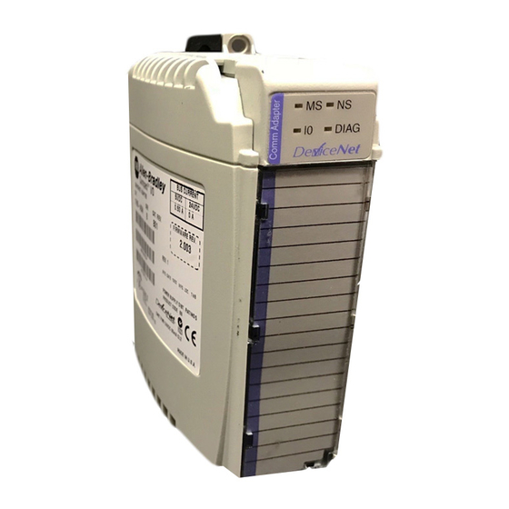
DeviceNet node address rotary identification label selection switches - Most Significant Digit (MSD) Stationary bus connector with male DeviceNet node address rotary pins selection switches - Least Significant Digit (LSD) Nameplate label Removable DeviceNet terminal Allen-Bradley connector Publication 1769-UM001B-EN-P - October 2002... -
Page 16: Module Installation
Installing Your DeviceNet Adapter Module Module Installation Compact I/O is suitable for use in an industrial environment when installed in accordance with these instructions. Specifically, this equipment is intended for use in clean, dry environments (Pollution degree 2 ) and circuits not exceeding Over Voltage Category II (IEC 60664-1). -
Page 17: System Assembly
7. Attach an end cap terminator (d) to the last I/O module in the system by using the tongue-and-groove slots as before. Allen-Bradley Publication 1769-UM001B-EN-P - October 2002... -
Page 18: Mounting The Adapter And An I/O Module
Installing Your DeviceNet Adapter Module 8. Lock the end cap bus terminator (e). A 1769-ECR or 1769-ECL right or left end cap IMPORTANT must be used to terminate the end of the serial communication bus. 9. Refer to the “DeviceNet Wiring” section on page 1-7. Mounting the Adapter and an I/O Module During panel or DIN rail mounting of all devices,... -
Page 19: Panel Mounting Procedure Using Modules As A Template
NOTE: If mounting more modules, mount only the last one of this group and put the others aside. This reduces remounting time during drilling and tapping of the next group. 7. Repeat steps 1 through 6 for any remaining modules. Allen-Bradley Publication 1769-UM001B-EN-P - October 2002... -
Page 20: Din Rail Mounting
Installing Your DeviceNet Adapter Module DIN Rail Mounting The adapter can be mounted using the following DIN rails: • 35 x 7.5mm (EN50022 - 35 x 7.5) • 35 x 15mm (EN 50022 - 35 x 15) Before mounting the module on a DIN rail, close the DIN rail latches. Press the DIN rail mounting area of the module against the DIN rail. -
Page 21: Field Wiring Connections
2. Insert the removable female connector into the mating male connector on the DeviceNet adapter module. 3. Screw the removable connector to the adapter case with the Allen-Bradley upper and lower mounting screws. Screw torque is 5-6 in-lbs. Publication 1769-UM001B-EN-P - October 2002... -
Page 22: Setting The Network Address Switches
If the 1769-ADN is the last device connected to the IMPORTANT DeviceNet network trunkline, be sure to add or move the termination resistor (Allen-Bradley part number 1485A-C2 or a 120 Ω 5% or > ¼W resistor) across the Blue (CAN Low) and White (CAN High) wires. -
Page 23: Configuring The 1769-Adn
For more information, refer to Configuring Your Compact I/O Series A DeviceNet Adapter in Chapter 3 or Configuring Your Compact I/O Series B DeviceNet Adapter in Chapter 4. Allen-Bradley Publication 1769-UM001B-EN-P - October 2002... - Page 24 1-10 Installing Your DeviceNet Adapter Module Notes: Publication 1769-UM001B-EN-P - October 2002...
-
Page 25: How Communication Takes Place And I/O Image Table Mapping
Status Words. This is followed by the input data from each slot, in the order of the installed I/O modules. The input data from Slot 1 is first after the status words, followed by Input data from Slot 2, and so on Allen-Bradley up to Slot 30. Publication 1769-UM001B-EN-P - October 2002... -
Page 26: Adapter Status Words
How Communication Takes Place and I/O Image Table Mapping The amount of input data in the adapter’s input image for each I/O module is based on the configuration of each I/O module done as part of the 1769-ADN configuration. If an I/O module is configured to have 0 words of input data, then it does not appear in the input image of the 1769-ADN. - Page 27 The node address changed bit is set when the node address switch setting has been changed since power up. The new node address does not take affect until the adapter has been powered down and then powered back up. Allen-Bradley Publication 1769-UM001B-EN-P - October 2002...
-
Page 28: Communication Choices
How Communication Takes Place and I/O Image Table Mapping Communication Choices The Compact I/O DeviceNet adapter module supports multiple communication choices. These choices all use the DeviceNet adapter input image and output image structure previously described. The DeviceNet master makes the actual communication choice. The choices are: Polled - data is sent by the adapter in response to received data... -
Page 29: 1769-Ia8I Individually Isolated 120V Ac Input Module (8 Point)
Input Data Module (16 Point) For each 1769-IA16 input module, input data word 0 contains the current state of the field input points. Bit Position 15 14 13 12 11 10 r = read Allen-Bradley Publication 1769-UM001B-EN-P - October 2002... -
Page 30: 1769-If4 (Series A And B) Analog Current/Voltage Input Module (4 Channel)
How Communication Takes Place and I/O Image Table Mapping 1769-IF4 (Series A and B) Input Data Analog Current/Voltage For each 1769-IF4 input module, input data words 0-3 contain the Input Module (4 Channel) analog value of the inputs. Word 4 and 5 contain analog status and error information. -
Page 31: 1769-Oa8 100 To 240V Ac Solid State Output Module (8 Point)
= read The output module’s input data reflects the output IMPORTANT data echo of the module, not necessarily the electrical state of the output terminals. It does not reflect shorted or open outputs. Allen-Bradley Publication 1769-UM001B-EN-P - October 2002... -
Page 32: 1769-Oa16 100 To 240V Ac Solid State Output Module (16 Point)
How Communication Takes Place and I/O Image Table Mapping 1769-OA16 100 to 240V AC Output Data File Solid State Output Module Data output bits are turned on or off using the bit positions in Word 0. (16 Point) 1 = output on 0 = output off Example: To turn on bit position 12, type 1 in Word 0, Bit 12. -
Page 33: 1769-Ob16 Solid State 24V Dc Source Output Module (16 Point)
= read The output module’s input data reflects the output IMPORTANT data echo of the module, not necessarily the electrical state of the output terminals. It does not reflect shorted or open outputs. Allen-Bradley Publication 1769-UM001B-EN-P - October 2002... -
Page 34: 1769-Ob16P Electronically Protected Solid-State 24V Dc Output Module
2-10 How Communication Takes Place and I/O Image Table Mapping 1769-OB16P Electronically Output Data Protected Solid-State 24V For each 1769-OB16P module, output data word 0 contains the DC Output Module control program’s directed state of the discrete output points. Bit Position 15 14 13 12 11 10 w = write Input Data... -
Page 35: 1769-Of2 (Series A And B) Analog Current/Voltage
Hx = hold last state bits. When set, they indicate that the channel is in a hold last state condition. The output module’s input data reflects the analog IMPORTANT output data echo of the module, not necessarily the electrical state of the output terminals. It does not Allen-Bradley reflect shorted or open outputs. Publication 1769-UM001B-EN-P - October 2002... -
Page 36: 1769-Ov16 Solid State 24V Dc Sink Output Module (16 Point)
2-12 How Communication Takes Place and I/O Image Table Mapping 1769-OV16 Solid State 24V Output Data DC Sink Output Module For each 1769-OV16 module, output data word 0 contains the control (16 Point) program’s directed state of the discrete output points. Bit Position 15 14 13 12 11 10 w = write... -
Page 37: 1769-Ow8 Ac/Dc Relay Output Module (8 Point)
= read The output module’s input data reflects the output IMPORTANT data echo of the module, not necessarily the electrical state of the output terminals. It does not reflect shorted or open outputs. Allen-Bradley Publication 1769-UM001B-EN-P - October 2002... -
Page 38: 1769-Ow8I Individually Isolated Ac/Dc Relay Output Module (8 Point)
2-14 How Communication Takes Place and I/O Image Table Mapping 1769-OW8I Individually Output Data Isolated AC/DC Relay For each 1769-OW8I module, output data word 0 contains the control Output Module (8 Point) program’s directed state of the discrete output points. Bits 8 to 15 are not used. -
Page 39: 1769-Ow16 Ac/Dc Relay Output Module (16 Point)
It does not reflect shorted or open outputs. It is important to use this input word if the controller adapter supports the Program Mode or Fault Mode function, and if it is configured to use them. Allen-Bradley Publication 1769-UM001B-EN-P - October 2002... -
Page 40: 1769-Iq6Xow4 24V Dc Sink/Source Input Ac/Dc Relay Output Module (6 Point In, 4 Point Out)
2-16 How Communication Takes Place and I/O Image Table Mapping 1769-IQ6XOW4 24V DC Output Data Sink/Source Input AC/DC For each 1769-IQ6XOW4 module, output data word 0 contains the Relay Output Module control program’s directed state of the discrete output points. Bits 4 to (6 Point In, 4 Point Out) 15 are not used. -
Page 41: 1769-It6 Thermocouple/Mv Input Module
(1) when a temperature measurement is above the normal operating range for a given thermocouple type. For millivolt inputs, the over-range bit indicates a voltage that is above the normal operating range. These bits can be used in the control program for error detection. Allen-Bradley Publication 1769-UM001B-EN-P - October 2002... -
Page 42: Input Data
2-18 How Communication Takes Place and I/O Image Table Mapping 1769-IR6 RTD/Resistance Input Data Input Module The first six words (0 to 5) of the input data file contain the analog RTD or resistance values of the inputs. Words 6 and 7 provide sensor/channel status feedback for use in your control program as shown below. -
Page 43: 1769-If4Xof2 Combination Analog Module
It is only important to use the loopback function of input words 6 and 7 if the controller supports the Allen-Bradley Program Mode or Fault Mode functions, and if it is configured to use them. Publication 1769-UM001B-EN-P - October 2002... -
Page 44: Output Data
2-20 How Communication Takes Place and I/O Image Table Mapping Output Data The output data file applies only to output data from the module as shown in the table below. Bits 0 through 6 and bit 15 of output data words 0 IMPORTANT and 1 should always be set to zero in your control program. -
Page 45: 1769-Hsc High-Speed Counter Module
Direct Write Value Range12To15[0].LowLimit Range Low Limit Range12To15[0].OutputControl Range Output Control Range Configuration Not Used Not Used LDW Type Not Used ToThisCtr Flags Range High Limit or Range12To15[1].HiLimOrDirWr Direct Write Value Range12To15[1].LowLimit Range Low Limit Allen-Bradley Publication 1769-UM001B-EN-P - October 2002... -
Page 46: Input Array
2-22 How Communication Takes Place and I/O Image Table Mapping Word Function Range12To15[1].OutputControl Range Output Control Range Configuration Not Used Not Used LDW Type Not Used ToThisCtr Flags Range High Limit or Range12To15[2].HiLimOrDirWr Direct Write Value Range12To15[2].LowLimit Range Low Limit Range12To15[2].OutputControl Range Output Control Range Configuration... - Page 47 Not Used C2PW CUdf COvf Counter 2 Status Flags Used Not Used Not Used Ctr[3].CurrentCount Counter 3 Current Count Ctr[3].CurrentRate Counter 3 Current Rate Not Used C3PW CUdf COvf Counter 3 Status Flags Used Allen-Bradley Publication 1769-UM001B-EN-P - October 2002...
-
Page 48: Defaults
2-24 How Communication Takes Place and I/O Image Table Mapping Defaults Factory defaults are the values assigned when you: • first power up the system, and • no previous user-programmed stored settings have been applied Each I/O module has default values associated with it. Module defaults for I/O size: Factory defaults Real time setting... - Page 49 I/O connections can be made. For more information, refer to Configuring Your Compact I/O Series A DeviceNet Adapter in Chapter 3 or Configuring Your Compact I/O Series B DeviceNet Adapter in Chapter 4. Allen-Bradley Publication 1769-UM001B-EN-P - October 2002...
- Page 50 2-26 How Communication Takes Place and I/O Image Table Mapping Notes: Publication 1769-UM001B-EN-P - October 2002...
-
Page 51: Configuring Your Compact I/O Series A Devicenet Adapter
Major Revision 1 icon within RSNetWorx, version 4.00 or later. A Major Revision 2 adapter will be added by selecting the “1769-ADN DeviceNet Adapter” top-level option within RSNetWorx, version 4.00 or later. Allen-Bradley Publication 1769-UM001B-EN-P - October 2002... -
Page 52: Configuring Your Compact I/O System Offline
Configuring Your Compact I/O Series A DeviceNet Adapter Configuring Your Compact Now that you’ve added the 1769-ADN DeviceNet adapter offline, you’ll need to configure the adapter and all of the devices in the I/O System Offline 1769 I/O system. Configuring Your Series A Adapter You’ll see this screen when you double-click on the 1769-ADN DeviceNet adapter icon. - Page 53 Notice that this field is now called Slot 1 if an I/O module was selected. This slot-numbering scheme will continue for each I/O module you add to the configuration. Note: Power supplies and cable are not assigned slot numbers. Allen-Bradley Publication 1769-UM001B-EN-P - October 2002...
- Page 54 Configuring Your Compact I/O Series A DeviceNet Adapter 2. Continue to list your devices down the left column and continue at the top right column if necessary. Note: To limit the need to reconfigure, make sure you understand the Configuration Rules for the Series A Adapter on page 3-7.
- Page 55 Configuration Rules for the Series A Adapter on page 3-7. 8. Choose Apply to be sure that your system passes the electrical audit. Allen-Bradley 9. After defining the devices on this 1769-ADN node, refer to the Publication 1769-UM001B-EN-P - October 2002...
- Page 56 Configuring Your Compact I/O Series A DeviceNet Adapter relevant sections on pages 3-9 to 3-20 to configure each 1769 I/O module. 10. Once all of the I/O modules are configured, choose OK. 11. From the File menu, choose Save. 12. Go on-line. 13.
-
Page 57: Using Banks Of I/O
– 180 words of input data from the I/O modules. – 180 words of output data for the I/O modules. – 724 words of configuration data for the I/O modules. • An end cap/terminator must be on the last I/O bank. Allen-Bradley Publication 1769-UM001B-EN-P - October 2002... - Page 58 Configuring Your Compact I/O Series A DeviceNet Adapter Example Configurations The following illustrations show examples of two valid system setups. Bank 1 I/O Slot Number Right-to-Right Cable Bank 2 I/O Slot Number Left-to-Left Cable Bank 3 I/O Slot Number Bank 1 Bank 2 Bank 3 I/O Slot Number...
-
Page 59: Configuring Discrete Input Modules
3. To change the revision key, enter a new revision value in the field marked revision. Note: 0 is not a valid revision number. Refer to the Comparison Feature section on page 3-22 for an explanation on the use of this field. Allen-Bradley Publication 1769-UM001B-EN-P - October 2002... - Page 60 3-10 Configuring Your Compact I/O Series A DeviceNet Adapter 4. You may choose from the pull-down menu to change the electronic keying to exact match, compatible module, or disable keying. • Exact Match: The programmed module type (e.g. 1769-IA16) and the revision must match exactly with the actual module. •...
-
Page 61: Configuring Discrete Output Modules
2. To change the input or output size, enter the new word value in the appropriate field. If you enter a non-valid number for a particular module, you will see a screen with a range of valid numbers. Allen-Bradley Publication 1769-UM001B-EN-P - October 2002... - Page 62 3-12 Configuring Your Compact I/O Series A DeviceNet Adapter 3. To change the revision key, enter a new revision value in the field marked revision. Note: 0 is not a valid revision number. Refer to the Comparison Feature section on page 3-22 for an explanation on the use of this field.
- Page 63 9. To apply the specific words/functions, check the appropriate box and choose OK. 10. Once you’ve finished making your changes, you may choose OK from the I/O Module screen to return to the Bank Configuration screen. Allen-Bradley Publication 1769-UM001B-EN-P - October 2002...
-
Page 64: Configuring Analog Input Modules
3-14 Configuring Your Compact I/O Series A DeviceNet Adapter Configuring Analog Follow these guidelines to configure analog input modules. Input Modules 1. From the Bank Configuration tab, click on the slot number of the analog input module you would like to configure. You’ll see a screen similar to this. - Page 65 The default is that the 1769 power supply is supplying the +24V for this module any time you perform an upload from the 1769-ADN. Therefore, when online refer to Auditing the Configuration on page 3-20. Allen-Bradley Publication 1769-UM001B-EN-P - October 2002...
- Page 66 3-16 Configuring Your Compact I/O Series A DeviceNet Adapter 8. If desired, choose Set for I/O Only to automatically modify the input/output sizes to real time size defaults and other configurations to their default values. 9. If desired, choose Data Description to view the definitions of each input and output word.
-
Page 67: Configuring Analog Output Modules
If you enter a non-valid number for a particular module, you will see a screen with a range of valid numbers. Refer to the Comparison Feature section on page 3-22 for an explanation on the use of this field. Allen-Bradley Publication 1769-UM001B-EN-P - October 2002... - Page 68 3-18 Configuring Your Compact I/O Series A DeviceNet Adapter 3. To change the revision key, enter a new revision value in the field marked revision. Note: 0 is not a valid revision number. Refer to the Comparison Feature section on page 3-22 for an explanation on the use of this field.
- Page 69 13. To apply the specific words/functions, check the appropriate box and choose OK. 14. Once you’ve finished making your changes, you may choose OK from the I/O Module screen to return to the Bank Configuration screen. Allen-Bradley Publication 1769-UM001B-EN-P - October 2002...
-
Page 70: Configuring Power Supplies, Cables, And End Cap
3-20 Configuring Your Compact I/O Series A DeviceNet Adapter Configuring Power Electronic keys for these devices are automatically set to Exact Match. No additional configuration is necessary. Supplies, Cables, and End Cap Completing Configuration After you’ve finished specifying the Series A adapter configuration and the individual device configurations (I/O modules, power supplies, cables, and end cap), choose Apply or OK to complete the offline configuration. -
Page 71: Configuring Your Compact I/O System Online
Once all configuration is successfully downloaded, RSNetworx has the 1769-ADN save all the configuration in non-volatile memory. This includes the Series A adapter configuration and the configuration of all of the 1769 devices. Allen-Bradley Publication 1769-UM001B-EN-P - October 2002... - Page 72 3-22 Configuring Your Compact I/O Series A DeviceNet Adapter Comparison Feature The comparison feature regards matching. A match or mismatch is determined based on a comparison of the programmed devices (the devices stored in the adapter’s non-volatile memory) and the actual devices present on the 1769 bus.
-
Page 73: Uploading Configurations
When you choose to pull the saved configuration, the individual I/O module configurations that had been saved by the 1769-ADN are used. When you choose to pull the actual device’s information, the individual I/O module configurations from the actual devices are used. Allen-Bradley Publication 1769-UM001B-EN-P - October 2002... -
Page 74: Downloading Configurations
3-24 Configuring Your Compact I/O Series A DeviceNet Adapter Downloading Configurations When you complete a configuration online and choose Apply or OK, assuming the configuration passes the audit, RSNetworx downloads the configuration to the 1769-ADN. The 1769-ADN then performs a key check on the requested devices. -
Page 75: Using The Clear Memory Function
DeviceNet master/scanner to make a connection. If any of the keys do not match, the 1769-ADN will not permit a DeviceNet master/scanner to make an I/O connection and will wait for a valid configuration. Allen-Bradley Publication 1769-UM001B-EN-P - October 2002... - Page 76 3-26 Configuring Your Compact I/O Series A DeviceNet Adapter Notes: Publication 1769-UM001B-EN-P - October 2002...
-
Page 77: Configuring Your Compact I/O Series B Devicenet Adapter
To add a Series B 1769-ADN adapter offline, double-click (or drag and drop) on the 1769-ADN DeviceNet Adapter selection on the left. DeviceNet Adapter Offline Notice that the adapter now appears on your network on the right. Allen-Bradley Publication 1769-UM001B-EN-P - October 2002... -
Page 78: Configuring Your Compact I/O System Offline
Configuring Your Compact I/O Series B DeviceNet Adapter Configuring Your Compact Now that you’ve added the Series B 1769-ADN DeviceNet adapter offline, you’ll need to configure the adapter and all of the devices in I/O System Offline the 1769 I/O system. Configuring Your Series B Adapter You’ll see this screen when you double-click on the 1769-ADN DeviceNet adapter icon. - Page 79 3. Once you have added all of the devices to the list in the correct order, assign the appropriate bank to each module. Allen-Bradley Publication 1769-UM001B-EN-P - October 2002...
- Page 80 Configuring Your Compact I/O Series B DeviceNet Adapter Follow these steps to assign banks to each module: a. Select the desired module and choose Properties. You’ll see a screen similar to this. b. Enter the bank number in the Bank field. To save time, assign the bank numbers to the first (left-most) modules in each bank, starting with bank one.
- Page 81 If no input or output sizes were changed, deactivating the adapter’s scanlist entry is usually not necessary. Allen-Bradley Publication 1769-UM001B-EN-P - October 2002...
-
Page 82: Using Banks Of I/O
Configuring Your Compact I/O Series B DeviceNet Adapter Using Banks of I/O Configuration Rules for Series B Adapters • The Series B adapter must be the first and left-most module in the system (the first module of Bank 1). • The Series B adapter can communicate with up to 30 modules in a system. - Page 83 1 (64K) sector of the external flash part, enabling the maximum for each module to be supported, regardless of the number of modules. • An end cap/terminator must be on the last I/O bank. Allen-Bradley Publication 1769-UM001B-EN-P - October 2002...
- Page 84 Configuring Your Compact I/O Series B DeviceNet Adapter Example Configurations The following illustrations show examples of two valid system setups. Bank 1 I/O Slot Number Right-to-Right Cable Bank 2 I/O Slot Number Left-to-Left Cable Bank 3 I/O Slot Number Bank 1 Bank 2 Bank 3 I/O Slot Number...
-
Page 85: Configuring Discrete Input Modules
To save time, assign the bank numbers to the first (left-most) modules in each bank, starting with bank one. The software ripples the bank modification down the list when you close the module’s property window. Allen-Bradley Publication 1769-UM001B-EN-P - October 2002... - Page 86 4-10 Configuring Your Compact I/O Series B DeviceNet Adapter 3. From the Advanced Parameters tab, you can configure editable parameters by selecting from the pull-down menus or directly typing in the value. You can configure the Input Data Size parameter to No Input Data or Input Data (1 Word).
- Page 87 Access to the EDS file is provided to enable you to determine which version of the device’s EDS file is installed on your system. The most up-to-date EDS file Allen-Bradley brand modules may be obtained at http://www.ab.com/networks/eds/ or by contacting your local Rockwell Automation representative.
-
Page 88: Configuring Discrete Output Modules
4-12 Configuring Your Compact I/O Series B DeviceNet Adapter 7. When you have finished looking at the EDS file, close the Notepad window. 8. Choose OK to return to the Module Configuration tab. Configuring Discrete Follow these guidelines to configure discrete output modules. Output Modules 1. - Page 89 • Disable: Any module may be used as a replacement. Refer to the Comparison Feature section on page 4-29 for an explanation on the use of this field. Allen-Bradley Publication 1769-UM001B-EN-P - October 2002...
- Page 90 4-14 Configuring Your Compact I/O Series B DeviceNet Adapter 4. From the Configuration Settings tab, double-click on the Program State or Fault State groups to configure them. You will see a screen similar to this one when you select a Program State group.
- Page 91 Access to the EDS file is provided to enable you to determine which version of the device’s EDS file is installed on your system. The most up-to-date EDS file Allen-Bradley brand modules may be obtained at http://www.ab.com/networks/eds/ or by contacting your local Rockwell Automation representative.
- Page 92 4-16 Configuring Your Compact I/O Series B DeviceNet Adapter Changes to this file are not recommended except for users with appropriate training or under the guidance of Rockwell Automation, Inc. authorized technical support representative. 7. Choose View to see the EDS file. 8.
-
Page 93: Configuring Analog Input Modules
To save time, assign the bank numbers to the first (left-most) modules in each bank, starting with bank one. The software ripples the bank modification down the list when you close the module’s property window. Allen-Bradley Publication 1769-UM001B-EN-P - October 2002... - Page 94 4-18 Configuring Your Compact I/O Series B DeviceNet Adapter 3. From the Advanced Parameters tab, you can configure editable parameters by selecting from the pull-down menus or directly typing in the value. You can configure the Input Data Size parameter to No Input Data or 1-6 Words.
- Page 95 (4 to 20mA), or (1 to 5V dc). You can configure Data Format to Raw/Proportional Data, Engineering Units, Scaled-for-PID, or Percent Range. For details on these options, refer to the Compact 1769 Analog I/O User Manual, publication 1769-6.0. 5. Choose OK. Allen-Bradley Publication 1769-UM001B-EN-P - October 2002...
- Page 96 Access to the EDS file is provided to enable you to determine which version of the device’s EDS file is installed on your system. The most up-to-date EDS file Allen-Bradley brand modules may be obtained at http://www.ab.com/networks/eds/ or by contacting your local Rockwell Automation representative.
-
Page 97: Configuring Analog Output Modules
Configuring Analog Follow these guidelines to configure analog output modules. Output Modules 1. From the Module Configuration tab, double-click on the output module you would like to configure. You’ll see a screen similar to this. Allen-Bradley Publication 1769-UM001B-EN-P - October 2002... - Page 98 4-22 Configuring Your Compact I/O Series B DeviceNet Adapter 2. To assign the module to a different bank, enter the bank number in the Bank field. To save time, assign the bank numbers to the first (left-most) modules in each bank, starting with bank one.
- Page 99 State parameter to Hold Last parameter to Raw/Proportional State or User-Defined Value. Data, Engineering Units, Scaled-for-PID, or Percent Range. For details on these options, refer to the Compact 1769 Analog I/O User Manual, publication 1769-6.0. 5. Choose OK. Allen-Bradley Publication 1769-UM001B-EN-P - October 2002...
- Page 100 Access to the EDS file is provided to enable you to determine which version of the device’s EDS file is installed on your system. The most up-to-date EDS file Allen-Bradley brand modules may be obtained at http://www.ab.com/networks/eds/ or by contacting your local Rockwell Automation representative.
-
Page 101: Configuring Power Supplies, Cables, And End Cap
OK, the offline configuration is complete and you return to the main RSNetworx for DeviceNet screen. If the audit fails, you will see an error describing the problems found. You’ll then need to return to the appropriate configuration section and make your changes. Allen-Bradley Publication 1769-UM001B-EN-P - October 2002... -
Page 102: Viewing The Mapping Summaries
4-26 Configuring Your Compact I/O Series B DeviceNet Adapter Viewing the Mapping Summaries 1. To view the mapping summaries, choose the I/O Summary tab. This is a summary of the configured size and format of the I/O data for the 1769-ADN. -
Page 103: Viewing The Transactions
I/O module and re-save (download) the final configuration back to the Series B 1769-ADN adapter. Online configuration is completed in the same way as the offline configuration with the addition of the following features: Allen-Bradley Publication 1769-UM001B-EN-P - October 2002... -
Page 104: Apply/Ok Button
4-28 Configuring Your Compact I/O Series B DeviceNet Adapter Apply/OK Button When you choose Apply or OK, the software downloads the configuration of the desired devices to the 1769-ADN if the key check on the system keying configuration has passed. If the downloaded system keying configuration (the configuration that identifies all the devices present, their location, and keying option) does not match the keys of the actual 1769 devices, the 1769-ADN... - Page 105 A major/minor revision of 2.3 is considered greater than a major/minor revision of 1.9. Remember, in order for the system keying configuration to be valid, all of the desired devices (modified by their keying option) must match. Allen-Bradley Publication 1769-UM001B-EN-P - October 2002...
-
Page 106: Uploading Configurations
4-30 Configuring Your Compact I/O Series B DeviceNet Adapter Uploading Configurations The first time you select a 1769-ADN from RSNetworx when online, the software will upload the configuration saved in the 1769-ADN. You may upload the saved configuration from the 1769-ADN at any time when online by clicking the right mouse button. -
Page 107: Downloading Configurations
I/O module configuration, with the configuration of the actual device. When you choose cancel, you can go back and edit your requested configuration without losing all of your previous configurations. Allen-Bradley Publication 1769-UM001B-EN-P - October 2002... -
Page 108: Configuring Your Adapter For Quick Connect Operation
4-32 Configuring Your Compact I/O Series B DeviceNet Adapter Configuring Your Adapter Quick Connect is a recently introduced DeviceNet feature that reduces the amount of time that slave devices (in this case, your 1769 for Quick Connect DeviceNet adapter) take to go from their powered-down state to a Operation state where they are ready to accept I/O connections. -
Page 109: Configured 1769-Adn Powerup Behavior
DeviceNet master/scanner to make a connection. If any of the keys do not match, the 1769-ADN will not permit a DeviceNet master/scanner to make an I/O connection and will wait for a valid configuration. Allen-Bradley Publication 1769-UM001B-EN-P - October 2002... - Page 110 4-34 Configuring Your Compact I/O Series B DeviceNet Adapter Notes: Publication 1769-UM001B-EN-P - October 2002...
-
Page 111: Diagnostic Indicators
• node address switch changed • main program checksum failed • configured I/O size too large Solid RED Unrecoverable fault • terminator/end cap missing • connector/cable between modules missing/not connected • bad configuration memory • watchdog tripped Allen-Bradley Publication 1769-UM001B-EN-P - October 2002... - Page 112 Troubleshooting with the Indicators LED Indication Meaning Network Status (NS) No DeviceNet power or no network access Flashing GRN/OFF On-line but not connected Solid GRN On-line and connected Flashing RED/OFF Connection time-out Solid RED Critical network failure I/O Status (IO) No power or outputs off Flashing GRN/OFF Idle/program mode - one or more I/O modules in Idle Mode...
-
Page 113: 1747-Sdn Application Example
SLC 500 and MicroLogix 1000 Instruction Set (publication 1747-RM001), the MicroLogix 1200 and 1500 Instruction Set (publication 1762-RM001), the SLC 500 Modular Hardware Style User Manual (publication Allen-Bradley 1747-RM011), and/or the RSLogix 500 help screens. Publication 1769-UM001B-EN-P - October 2002... -
Page 114: Configuring The 1769-Adn Devicenet Adapter
Application Examples Configuring the 1769-ADN DeviceNet Adapter Start RSNetworx for DeviceNet. At this point, you could configure your network devices offline and download these configuration files to the network devices. Instead, we will go online to configure our network. Refer to chapter 3 for information on configuring your DeviceNet system offline. - Page 115 These node address assignments are arbitrary and each device could be assigned any unique address from 00 to 63. To begin configuring your DeviceNet network you’ll configure the Compact I/O system. Double-click on the 1769-ADN icon. You’ll see this screen. Allen-Bradley Publication 1769-UM001B-EN-P - October 2002...
- Page 116 Application Examples Choose the Module Configuration tab. Choose Yes when asked if you want to upload. You’ll see this screen. The I/O Module Mismatch screen indicates that configuration has not yet been downloaded to the 1769-ADN. Choose Resolve Mismatch. You’ll see this screen. Notice that the 1769 system configuration software is now completely filled in with the actual I/O modules, power supplies, cable, and end cap.
- Page 117 Output Bytes as you’ll need this information when configuring the 1747-SDN scanner. Choose Apply. This will download your configuration to the 1769-ADN. Then choose OK to close the adapter’s window and return to the network screen. Allen-Bradley Publication 1769-UM001B-EN-P - October 2002...
-
Page 118: Configuring The 1747-Sdn
Application Examples Configuring the 1747-SDN To configure the 1747-SDN DeviceNet scanner to exchange I/O data with the 1769-ADN, double-click on the 1747-SDN. You’ll see this screen. The General tab supplies information about the scanner. Choose the Module tab and choose Upload on the Scanner Configuration screen. Once the upload is complete you’ll return to the Module tab. - Page 119 Choose the Every Scan poll rate. Refer to the 1747-SDN documentation for a complete description of Every Scan and Background Poll Rates. Refer to Appendix C for some important system characteristics when using the polled mode (minimum inter-scan delay I.D. for polled connections). Allen-Bradley Publication 1769-UM001B-EN-P - October 2002...
- Page 120 Application Examples Choose OK to accept the Polled configuration. You’ll now see the 1747-SDN Scanner Module screen. Choose the Input tab and you’ll see this screen. From this screen, you can map the input data received from the 1769-ADN into the input image table of the SLC 5/04 processor or to the M1 file.
-
Page 121: Accessing The I/O Data From The 1769-Adn In The Slc Processor
Use the Input and Output File Data Monitors in the programming software to experiment with viewing inputs and manipulating outputs, until you are comfortable with the I/O mapping to write your ladder program. Allen-Bradley Publication 1769-UM001B-EN-P - October 2002... - Page 122 6-10 Application Examples Input Image I:3.0 1747-SDN Status I:3.1 1769-ADN Status Word 0 I:3.2 1769-ADN Status Word 1 I:3.3 Slot 1 Input Card, Input Data (1769-IA16) I:3.4 Slot 2 Output Card, Output Echo Data (1769-OW8) I:3.5 Slot 3 Input Card, Input Data (1769-IA16) I:3.6 Slot 4 Output Card, Output Echo Data (1769-OW8) I:3.7...
-
Page 123: 1756-Dnb Application Example
DeviceNet Cable 1769- 1769- 1769-PB2 1769- 1769- 1769- 1769- 1769- 1769- 1769- IA16 IA16 IQ6X IQ6X IQ16 OV16 1769-CRL 1769- 1769- 1769- 1769-PA2 1769- 1769- 1769- IQ16 OB16 IQ16 OV16 1769-ECR 42322A Allen-Bradley Publication 1769-UM001B-EN-P - October 2002... -
Page 124: Configuring The Logix5550Tm Controller System
6-12 Application Examples Configuring the Logix5550 Controller System Configure your Logix5550 system by selecting the 1756-DNB module under I/O configuration in RSLogix 5000 programming software. For more information on configuring your controller or writing the controller program, refer to your ControlLogix documentation. The following sections will guide you through configuring your 1756-DNB module to produce output data to the 1769-ADN and consume input data from the 1769-ADN. - Page 125 Note that this example has the 1756-DNB at node address 01, the 1769-ADN at node address 30, and the 1784-PCD at node address 62. These node address assignments are arbitrary and each device could be assigned any unique address from 00 to 63. Allen-Bradley Publication 1769-UM001B-EN-P - October 2002...
- Page 126 6-14 Application Examples To begin configuring your DeviceNet network, you’ll configure the Compact I/O system. Double-click on the 1769-ADN icon. You’ll see this screen. Choose the Module Configuration tab. Choose Yes when asked if you want to upload. You’ll see this screen. The I/O Module Mismatch screen indicates that configuration has not yet been downloaded to the 1769-ADN.
- Page 127 The input word contains an echo of the output data. You could disable this echo to save input image, but for this example we will leave the echo enabled. Allen-Bradley Publication 1769-UM001B-EN-P - October 2002...
-
Page 128: Configuring The 1756-Dnb
6-16 Application Examples Choose the I/O Summary tab for the 1769-ADN DeviceNet adapter. You’ll see this screen. This is a summary of your 1769 system. Note the Total Input and Output Bytes as you’ll need this information when configuring the 1756-DNB scanner. - Page 129 Choose the Every Scan poll rate. Refer to the 1756-DNB documentation for a complete description of Every Scan and Background Poll Rates. Refer to Appendix C for some important system characteristics when using the polled mode (minimum inter-scan delay I.D. for polled connections). Allen-Bradley Publication 1769-UM001B-EN-P - October 2002...
- Page 130 6-18 Application Examples Choose OK to accept the Polled configuration. You’ll now see the 1756-DNB Scanner Module screen. Choose the Input tab and you’ll see this screen. From this screen, you can map the input data received from the 1769-ADN into the input tag of the Logix5550 controller or 1:I.Data.0 through 1:I.Data.12 (these are DINTs, so the total number of 16-bit words is 26 or 52 bytes).
-
Page 131: Accessing The I/O Data From The 1769-Adn In The Logix5550 Controller
Use the Controller Tags screen in the programming software to experiment with viewing inputs and manipulating outputs, until you are comfortable enough with the I/O mapping to write your Logix 5550 controller program. Allen-Bradley Publication 1769-UM001B-EN-P - October 2002... - Page 132 6-20 Application Examples Slot 1 Input Tag Map 1:I.Data0L 1769-ADN Status Word 0 1:I.Data.0H 1769-ADN Status Word 1 1:I.Data.1L Slot 1 Input Card, Input Data (1769-IA16) 1:I.Data.1H Slot 2 Output Card, Output Echo Data (1769-OW8) 1:I.Data.2L Slot 3 Input Card, Input Data (1769-IA16) 1:I.Data.2H Slot 4 Output Card, Output Echo Data (1769-OW8) 1:I.Data.3L...
- Page 133 This COP Instruction example also accomplishes the same purpose for the output data. The integer tag name is Output_Buffer and the length for this example is 5 DINTS, where the High word of DINT 1:O.Data.4 is not used. Allen-Bradley Publication 1769-UM001B-EN-P - October 2002...
- Page 134 6-22 Application Examples 1769-SDN Application This example uses the 1769-SDN scanner module with a MicroLogix 1500 controller. Example MicroLogix 1500 Controllers The MicroLogix 1500 programmable controller has two different processors that are compatible with the 1769-SDN scanner module. The 1764-LSP and 1764-LRP processors can use the scanner as a DeviceNet master and own DeviceNet slave devices.
- Page 135 Bank with 1769-SDN Module 1770-KFD PC Communication Module DANGER DANGER Series 9000 MicroLogix 1000 Controller MicroLogix 1200 Controller Photoeye Connected via 1761-NET-DNI Connected via 1761-NET-DNI RediSTATION 1305 Drive Connected via 1203-GU6 Enhanced DeviceNet Communications Module Allen-Bradley Publication 1769-UM001B-EN-P - October 2002...
- Page 136 6-24 Application Examples Starting the Project 1. Open RSLogix 500. 2. Select File. 3. New. 4. Choose MicroLogix 1500 LRP series C. 5. The screen capture below should match what you see on your computer. In this example the name for this application is “TEMP”. In the TEMP window you see everything associated with the application.
- Page 137 (right window), to the appropriate slot on the left. Note, you cannot have open slots, modules must be contiguous from 1 to 16. Allen-Bradley Series B base units will be available late in 2001. Contact your local Allen-Bradley distributor for availability. Publication 1769-UM001B-EN-P - October 2002...
- Page 138 6-26 Application Examples Read I/O Configuration The next screen that appears is a communications dialog that allows you to select a communication path using RSLinx to the MicroLogix controller. If you have previously connected to a controller, the communications driver that you used before will be the active driver. This dialog screen provides the ability to change the driver or perform a Who Active across a network to locate the specific MicroLogix controller.
- Page 139 The first 2 words (0 and 1) are required by the scanner for status. DeviceNet slave output data words start at slot word 2. You can have a maximum of 180 output words for DeviceNet slave devices (maximum slot amount for scanner outputs = 182). Allen-Bradley Publication 1769-UM001B-EN-P - October 2002...
- Page 140 6-28 Application Examples Changing the 1769-SDN Configuration Changing (adding or removing) the amount of data the controller has assigned to the scanner is done in the expansion module configuration screen. From within RSLogix 500, I/O configuration, open the 1769-SDN scanner module and change the input or output words as needed.
- Page 141 You can use two different types of messages to exchange information with the DeviceNet device. The type of message used is determined by the destination device. You can generate a PCCC message or a CIP message. Allen-Bradley Publication 1769-UM001B-EN-P - October 2002...
- Page 142 Commands”. PCCC provides point to point and master/slave communications between devices. PCCC is an open protocol that is built into all Allen-Bradley controllers, and many other Allen-Bradley and third-party products. PCCC messaging has been used for many years on DH-485, DH+ and Ethernet networks, and for point-to-point communications between Allen-Bradley controllers.
- Page 143 In this example, upload/download can be performed with the devices at nodes 5, 6, 7 and 32. Node 32 is a 1769-SDN. Simply highlight the 1769-SDN and then click on either the upload or download button on the right side of the screen. Allen-Bradley Publication 1769-UM001B-EN-P - October 2002...
- Page 144 6-32 Application Examples Configuring a Local This section describes how to configure a local message using the scanner and a MicroLogix 1500 1764-LRP processor. DeviceNet Message Message Setup Screen Rung 0 shows a standard RSLogix 500 message (MSG) instruction preceded by conditional logic. 1.
- Page 145 1769-SDN scanner modules with full messaging functionality. You can use multiple 1769-SDN scanner modules in a MicroLogix 1500 system, but you can only message through the first two. Any other 1769-SDN scanner can only be used for I/O scanning. Allen-Bradley Publication 1769-UM001B-EN-P - October 2002...
- Page 146 6-34 Application Examples Communication Command The 1764-LRP processor supports the six standard types of communications commands (same as all other MicroLogix 1200 and 1500 controllers) and CIP Generic. When any of these six standard commands are chosen, you can initiate standard messages to destination devices connected to DeviceNet products that support PCCC messaging (including MicroLogix and SLC controllers using 1761-NET-DNI’s, other MicroLogix 1500 controllers using 1769-SDN...
- Page 147 CIP stands for “Control & Information Protocol”. CIP is a newer and more versatile protocol than PCCC. It is an open protocol that is supported by newer Allen-Bradley controllers and third-party products. CIP messaging is the native messaging format for DeviceNet. All DeviceNet devices are compliant with CIP messaging.
- Page 148 6-36 Application Examples Data Table Address (Receive and Send) This value identifies the data file location within the 1764-LRP controller that will receive data from the DeviceNet device, and/or the starting data file location that will be sent to the destination DeviceNet device.
- Page 149 DeviceNet parameter on the scanner, select Module. This allows the control program access to module parameters. Note, many module parameters are not editable, and some can only be edited when the module is in Idle Mode. Allen-Bradley Publication 1769-UM001B-EN-P - October 2002...
- Page 150 6-38 Application Examples Local Node address This is the target device’s DeviceNet node number. Service DeviceNet uses services to provide specific messaging functions. A number of standard services with their corresponding parameters have been preconfigured for ease of use. If you need to use a service that is not available, select one of the Generic services.
- Page 151 Object State Conflict Attribute Not Setable Device State Conflict Reply Data Too Large Not Enough Data Attribute Not Supported Too Much Data Object Does Not Exist Store Operation Failure Invalid Parameter Invalid Member ID Allen-Bradley Publication 1769-UM001B-EN-P - October 2002...
- Page 152 6-40 Application Examples Notes: Publication 1769-UM001B-EN-P - October 2002...
-
Page 153: 1769-Adn Specifications
(IEC1000-4-5) • Conducted Immunity 10V, 0.15 to 80 MHz (IEC1000-4-6) 1. Conducted immunity frequency range may be 150 kHz to 30 MHz if the Radiated Immunity frequency range is 30 MHz to 1000 MHz. Allen-Bradley Publication 1769-UM001B-EN-P - October 2002... -
Page 154: Series A Adapters Input/Output Specifications
Diagnostic status- red/grn DeviceNet Power 24V dc (+4%) @ 90mA maximum, N.E.C. Class 2 Requirements Allen-Bradley part no. 1485C-P1-Cxxx. Refer to DeviceNet Cable publication DN-2.5 for more information. Power Supply Distance Rating (The adapter may not be more than 4 modules away from the power supply.) -
Page 155: Series B Adapters Firmware General Specifications
Surge Transient Immunity IEC 61000-4-5: +2kV line-earth (CM) on shielded ports Conducted RF Immunity IEC 61000-4-6: 3Vrms with 1kHz sine-wave 80%AM from 10kHz to 80MHz 10Vrms with 1kHz sine-wave 80%AM from 150kHz to 80MHz Allen-Bradley Publication 1769-UM001B-EN-P - October 2002... - Page 156 Specifications Specification Value Enclosure Type Rating None (open-style) Certifications (When Product c-UL-us UL Listed for Class I, Division 2 Group is Marked) A,B,C,D Hazardous Locations, certified for U.S. and Canada European Union 89/336/EEC EMC Directive, compliant with: - EN 50082-2; Industrial Immunity - EN 61326;...
-
Page 157: Series B Adapters Input/Output Specifications
24V dc (+4%) @ 90mA maximum, N.E.C. Class 2 Requirements DeviceNet Cable Allen-Bradley part no. 1485C-P1-Cxxx. Refer to publication DN-2.5 for more information. Power Supply Distance Rating 4 (Series A); 5 (Series B) (The adapter may not be more than 4 or 5 modules away from the power supply, depending on the Series.) - Page 158 Specifications Notes: Publication 1769-UM001B-EN-P - October 2002...
-
Page 159: 1756-Dnb Explicit Messaging Application Example
1769-ADN or 1769 I/O module from a Logix5550 controller via a 1756-DNB DeviceNet scanner. You’ll see in the ladder logic example to follow, a CIP Generic message is sent to the 1756-DNB scanner and Allen-Bradley ultimately to the 1769-ADN. Publication 1769-UM001B-EN-P - October 2002... - Page 160 Explicit Messaging Application Examples Use a “Single Parameter Read” MSG instruction for the Get 1769-ADN Status message, where one word of status information is read from the 1769-ADN. The user program consists of a single rung containing a MSG instruction to accomplish the Get 1769-ADN Status. The following correlates the CIP Generic message terminology with DeviceNet command terminology and illustrates the values needed specifically for the Get 1769-ADN Status message:...
- Page 161 When true, indicates the device has experienced a Major Unrecoverable Fault 12-15 Reserved, set to 0 Refer to the Troubleshooting information in Chapter 4 for additional information on Recoverable and Unrecoverable, Major and Minor faults. Allen-Bradley Publication 1769-UM001B-EN-P - October 2002...
-
Page 162: Get 1769 I/O Module Status
Explicit Messaging Application Examples Get 1769 I/O Module Status Use a “CIP Generic” MSG instruction to send the Get 1769 I/O Module Status explicit message from a Logix5550 controller via a 1756-DNB scanner on DeviceNet. You’ll see in the ladder logic example to follow, a CIP Generic message is sent to the 1756-DNB scanner and ultimately to the 1769-ADN and the 1769 I/O module in slot 10. - Page 163 You only need to enter the path on this screen. “DNET” refers to the module on the 1756 backplane to which the message is sent. “2” is the DeviceNet port on the 1756-DNB. “19” is the DeviceNet address of the 1769-ADN. Allen-Bradley Publication 1769-UM001B-EN-P - October 2002...
-
Page 164: Get 1769 I/O Module Configuration Size
Explicit Messaging Application Examples The status word written to the tag specified in the destination field of the MSG instruction is defined as follows: Description 0 = No module error detected 1 = Module detected error present 0 = Communication on bus OK 1 = Communication Fault on bus 0 = Module is not configured 1 = Module is configured... - Page 165 This MSG instruction logic is specifically for the Get 1769 I/O Module Configuration Size message. Assume the 1756-DNB scanner is in slot 1 and the Logix5550 controller is in slot 0. Allen-Bradley Publication 1769-UM001B-EN-P - October 2002...
-
Page 166: Set 1769 I/O Module Configuration
Explicit Messaging Application Examples The following screen is the Communications tab for the MSG instruction above. The reply to this message, when successful, will be one word of data containing the word length of the configuration file for the 1769 I/O module to which the message was sent. - Page 167 I/O Module Configuration command 0 rather than 1862 hexadecimal, the MSG instruction will set the error bit and display an Error Code of 0009 hexadecimal with an Extended Error Code of 00ff hexadecimal. The error description is “Parameter error in module configuration”. Allen-Bradley Publication 1769-UM001B-EN-P - October 2002...
- Page 168 B-10 Explicit Messaging Application Examples The following ladder logic program is an example of the MSG logic needed to initiate an explicit message to the scanner/adapter. This MSG instruction logic is specifically for the Set 1769 I/O Module Configuration message. Assume the 1756-DNB scanner is in slot 1 and the Logix5550 controller is in slot 0.
-
Page 169: Save 1769 I/O Module Configuration
Class specifies the desired DeviceNet class. “f” hexadecimal is the class code for the object responsible for saving configuration, the parameter object. Instance for the save command is 00. There is no Object Attribute for the Save 1769 I/O Module Configuration message. Allen-Bradley Publication 1769-UM001B-EN-P - October 2002... - Page 170 B-12 Explicit Messaging Application Examples The following ladder logic program is an example of the MSG logic needed to initiate an explicit message to the scanner/adapter. This MSG instruction logic is specifically for the Save 1769 I/O Module Configuration message. Assume the 1756-DNB scanner is in slot 1 and the Logix5550 controller is in slot 0.
-
Page 171: Get 1769 I/O Module Configuration
Instance represents the slot number of the I/O module from which we want the configuration data. “10” decimal in this example is the analog output module in slot 10. Attribute identifies the specific characteristics of the object towards which the transaction is directed. “1a” hexadecimal means configuration data. Allen-Bradley Publication 1769-UM001B-EN-P - October 2002... - Page 172 B-14 Explicit Messaging Application Examples The following ladder logic program is an example of the MSG logic needed to initiate an explicit message to the scanner/adapter. This MSG instruction logic is specifically for the Get 1769 I/O Module Configuration message. Assume the 1756-DNB scanner is in slot 1 and the Logix5550 controller is in slot 0.
-
Page 173: 1747-Sdn Explicit Messaging Application Example
The user program is notified that the command reply is ready when the scanner sets an input image bit (I:s/15, where s is the slot number of the 1747-SDN). When this bit is set, the user program COPies the reply from the scanner’s M1 file. Allen-Bradley Publication 1769-UM001B-EN-P - October 2002... - Page 174 B-16 Explicit Messaging Application Examples Following each command reply, the user program must MOVe a command value of 4 hexadecimal to the appropriate M0 file word to clear the previous reply from its buffer, making it ready for the next command.
- Page 175 Assume the 1747-SDN scanner is in slot 3 of the processor chassis. Data Table File N11 (Shown in Hexadecimal Radix) Offset N11:0 N11:10 0 N11:20 0 N11:30 0 N11:40 4 N11:50 101 8E13 Allen-Bradley Publication 1769-UM001B-EN-P - October 2002...
-
Page 176: Get 1769 I/O Module Status
B-18 Explicit Messaging Application Examples The actual status word in the reply, i.e., the fourth word of the reply, is defined as follows: Description When true, indicates the device has an owner Reserved, set to 0 When true, indicates the application of the devices has been configured beyond out-of-the-box defaults Reserved, set to 0 Vendor specific... - Page 177 10 or “000A” hexadecimal. Attribute identifies the specific characteristic of the object towards which the transaction is directed. “000C” means Module Status. The attribute data size is one word. Allen-Bradley Publication 1769-UM001B-EN-P - October 2002...
- Page 178 B-20 Explicit Messaging Application Examples The following ladder logic program is an example of the logic needed to initiate an explicit message to the scanner/adapter/1769 I/O module and how to obtain the reply. This logic is specifically for the Get 1769 I/O Module Status command. Assume the 1747-SDN scanner is in slot 3 of the processor chassis and the 1769-OF2 module that we are reading status from is in slot 10 of the 1769-ADN remote system.
- Page 179 0 = No module error detected 1 = Module detected error present 0 = Communication on bus ok 1 = Communication fault on bus 0 = Module is not configured 1 = Module is configured Reserved, set to 0 Allen-Bradley Publication 1769-UM001B-EN-P - October 2002...
-
Page 180: Get 1769 I/O Module Configuration Size
B-22 Explicit Messaging Application Examples Get 1769 I/O Module Configuration Size 1769 I/O modules should be configured in RSNetworx for DeviceNet when your DeviceNet system is configured. We’ll describe how to modify 1769 I/O module configuration parameters while the system is running. -
Page 181: Set 1769 I/O Module Configuration
Seventh word of the 1769-OF2 configuration file 0000 Eighth word of the 1769-OF2 configuration file Successful Reply (Hexadecimal) Description (High Byte/Low Byte) 0101 TXID /Command 0000 Port # /Byte Count 9013 Service /Mac ID Continued on next page. Allen-Bradley Publication 1769-UM001B-EN-P - October 2002... - Page 182 B-24 Explicit Messaging Application Examples Error Reply (Hexadecimal) Description (High Byte/Low Byte) 0101 TXID /Command 0002 Port # /Byte Count 9413 Service /Mac ID xxxx Bad Status for the Configuration Command TXID (Transmission ID) is used by the scanner to track the transaction to completion and returns the same value with the reply.
- Page 183 Not enough data - The service did not supply enough data to perform the specified operation. Attribute not supported - The attribute specified in the request is not supported. Allen-Bradley Too much data - The service supplied more data than was expected. Publication 1769-UM001B-EN-P - October 2002...
- Page 184 B-26 Explicit Messaging Application Examples Error Code Description of Error (Hexadecimal) Object does not exist - The object specified does not exist in the device. Reserved by DeviceNet No stored attribute data - The attribute data of this object was not saved prior to the requested service.
-
Page 185: Save 1769 I/O Module Configuration
I/O module in question. This also indicates that the new configuration parameters sent to the I/O module with the explicit message would be lost. Refer to the Ladder Logic Example Program on page B-30 for this command’s ladder logic. Allen-Bradley Publication 1769-UM001B-EN-P - October 2002... -
Page 186: Get 1769 I/O Module Configuration
B-28 Explicit Messaging Application Examples The following table illustrates the Save 1769 I/O Module Configuration command and the command reply: Command (Hexadecimal) Description (High Byte/Low Byte) 0101 TXID /Command 0004 Port # /Byte Count 1613 Service /Mac ID 000F Class 0000 Instance Reply (Hexadecimal) - Page 187 Program mode. For this example, these four values must be in the range of 6241 or 31207 decimal (1862 to 79E7 hexadecimal), which represents 4-20mA. Any values out of this range will result in a Allen-Bradley configuration error.
-
Page 188: Ladder Logic Example Program
B-30 Explicit Messaging Application Examples Ladder Logic Example Program The following ladder program is an example of the logic needed to initiate explicit messages to the scanner/adapter/1769 I/O modules and how to obtain the replies. Assume the 1747-SDN is in slot 3 and the 1769-OF2 module is in 0A hexadecimal (10 decimal). -
Page 189: Discrete Module Configuration Files
Fault Value Word (word 4) is used to program the fault state value (0 = Off, 1 = On). Each output is Allen-Bradley individually configurable for on or off. Off = Bit Setting 0 and On = Bit Setting 1... - Page 190 B-32 Explicit Messaging Application Examples Notes: Publication 1769-UM001B-EN-P - October 2002...
-
Page 191: Appendix C Series A Adapters
• the output module’s turn-on/off time • the input module’s filter time • time for the 1769-ADN to collect the (new) values from the input modules • time for the 1769-ADN to transmit the complete input-update on the network Allen-Bradley Publication 1769-UM001B-EN-P - October 2002... -
Page 192: Minimum Inter-Scan Delay (Isd) For Polled Connections
1769-ADN Throughput Characteristics Note: The following equations represent the 1769-ADN turn-around time using a discrete input (1769-IQ16) and output (1769-OV16) pair wired in a loop-back fashion. For this configuration, the settling/filter time of the two modules is 8.6ms on average . -
Page 193: Quick Connect Performance
A 30-module system with a mix of 22 discrete and 8 analog modules took approximately 1.8s to startup. Adding the power supply startup time with the adapter’s startup process time estimate will provide an estimate of the adapter system’s overall Quick Connect startup time. Allen-Bradley Publication 1769-UM001B-EN-P - October 2002... -
Page 194: Quick Connect Limitations
1769-ADN Throughput Characteristics Quick Connect Limitations The 1769-HSC is not compatible with the 1769 adapter’s Quick Connection operation. The 1769-HSC does not respond quickly enough to adapter requests after startup. In general, modules that require longer than 650ms after power is applied to respond to the adapter will not be compatible with the adapter’s Quick Connect mode of operation. -
Page 195: Appendix D About The Differences
B is slightly more than the Series A due to the revised hardware memory architecture. • Series B and RSNetWorx (version 4.01) are required for compatibility with these modules: – 1769-IF4XOF2 – 1769-HSC – 1769-OW16 – 1769-OA16 – all future 1769 I/O modules • Quick Connect Allen-Bradley Publication 1769-UM001B-EN-P - October 2002... - Page 196 Differences Between Series A and B DeviceNet Adapters Notes: Publication 1769-UM001B-EN-P - October 2002...
- Page 197 ___Yes, please call me ___Yes, please email me at __________________________ ___Yes, please contact me via ________________________ Return this form to: Allen-Bradley Marketing Communications, 1 Allen-Bradley Dr., Mayfield Hts., OH 44124-9705 Allen-Bradley Phone: 440-646-3176 Fax: 440-646-3525 Email: [email protected] Publication ICCG-5.21- January 2001...
- Page 198 PLEASE FASTEN HERE (DO NOT STAPLE) Other Comments PLEASE FOLD HERE NO POSTAGE NECESSARY IF MAILED IN THE UNITED STATES BUSINESS REPLY MAIL FIRST-CLASS MAIL PERMIT NO. 18235 CLEVELAND OH POSTAGE WILL BE PAID BY THE ADDRESSEE 1 ALLEN-BRADLEY DR MAYFIELD HEIGHTS OH 44124-9705...
- Page 199 3-20, 4-25 3-8, 4-8 configuration example 3-20, 4-25 power supplies 3-7, 4-6 rules 3-2, 4-2 system offline Configuring SLC system 1747-SDN application example 2-21 Counter Control Bits 2-23 Current Count Cyclic data Allen-Bradley Publication 1769-UM001B-EN-P - October 2002...
- Page 200 1747-SDN application example 2-24 Defaults 2-21 Output Array DeviceNet wiring Diagnostic indicators 3-7, 4-6 I/O banks DIN rail mounting I/O structure 3-22, 4-29 Disable keying Image table Discrete input modules mapping data 3-9, 4-9 configuring 1769-IA16 Discrete output modules 1769-IA8I 3-11, 4-12 configuring 1769-IF4...
- Page 201 Output On Mask Structure Switches setting network address Panel mounting System using modules as template assembly Polled data replacing adapter Power remove Power supplies 3-20, 4-25 configuring 3-23, 4-30 Upload configurations Publications See Documentation 2-21 utput Allen-Bradley Publication 1769-UM001B-EN-P - October 2002...
- Page 202 Wiring DeviceNet field connections Word input status Publication 1769-UM001B-EN-P - October 2002...
- Page 203 Allen-Bradley Publication 1769-UM001B-EN-P - October 2002...
- Page 204 Back Cover Publication 1769-UM001B-EN-P - October 2002 PN 957555-75 Supersedes Publication 1769-UM001A-US-P - May 2000 Copyright © 2002 Rockwell Automation. All rights reserved. Printed in the U.S.A.