
Related Manuals for Motorola GP300 Series


Summary of Contents for Motorola GP300 Series
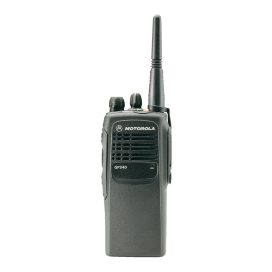
- Page 1 Professional Radio GP300 Series Basic Service Manual 6864115B18-D Issue: September 2007...
- Page 2 Accordingly, any copyrighted Motorola computer programs contained in the Motorola products described in this manual may not be copied or reproduced in any manner without the express written permission of Motorola. Furthermore, the purchase of Motorola prod-...
- Page 3 Read this information before using the radio. PRODUCT SAFETY AND RF EXPOSURE FOR PORTABLE TWO-WAY RADIOS. This document provides information and instructions for the safe and efficient operation of Motorola Portable Two-Way Radios. RF Energy Exposure Awareness and Control Information and Operational...
- Page 4 Compliance with RF Exposure Standards Your Motorola two-way radio is designed and tested to comply with a number of national and International standards and guidelines (listed below) for human exposure to radio frequency electromagnetic energy. This radio complies with the IEEE (FCC) and ICNIRP exposure limits for occupational/controlled RF exposure environments at operating duty factors of up to 50% talk- 50% listen and is authorized by the IEEE/ICNIRP for occupational use only.
- Page 5 Motorola - approved antennas, batteries and accessories may exceed IEEE/ICNIRP RF exposure guidelines. For a list of Motorola-approved antennas, batteries, and other accessories please see your dealer or local Motorola contact. Your nearest dealer can be found at the following web site: http://www.motorola.com/cgiss/emea/dealerlocator.html Additional Information For additional information on exposure requirements or other training information, visit http://www.motorola.com/rfhealth.
- Page 6 ELECTROMAGNETIC INTERFERENCE/COMPATIBILITY NOTE: Nearly every electronic device is susceptible to electromagnetic interference (EMI) if inadequately shielded, designed or otherwise configured for electromagnetic compatibility. Facilities To avoid electromagnetic interference and/or compatibility conflicts, turn off your radio in any facility where posted notices instruct you to do so. Hospitals or health care facilities may be using equipment that is sensitive to external RF energy.
- Page 7 OPERATIONAL WARNINGS Vehicles with an air bag Refer to vehicle manufacturer's manual prior to installation of electronic equipment to avoid interference with air bag wiring. WARNING: Do not place a portable radio in the area over an air bag or in the air bag deployment area.
- Page 8 Warnings for Radios Approved as Intrinsically Safe Radios must ship from the Motorola manufacturing facility with the hazardous atmosphere capability and the intrinsic safety approval labelling (FM, UL, CSA, CENELEC or ATEX). Radios will not be upgraded to this capability and labeled once they have been shipped to the field.
- Page 9 The manual PN referenced on the Intrinsically Safe Approval Label identifies the approved Accessories and or options that can be used with that portable radio unit. Using a non Motorola intrinsically safe battery and or accessory with the Motorola approved radio unit will void the intrinsically safe approval of that radio unit.
- Page 10 THIS PAGE INTENTIONALLY LEFT BLANK...
-
Page 11: Table Of Contents
Table of Contents Chapter 1 INTRODUCTION 1.0 Scope of Manual....................1-1 2.0 Warranty and Service Support ................1-1 2.1 Warranty Period and Return Instructions ............1-1 2.2 After Warranty Period..................1-1 2.3 European Radio Support Centre (ERSC) ............1-2 2.4 Piece Parts..................... 1-2 2.5 Technical Support .................. - Page 12 MODEL CHART AND TEST SPECIFICATION 1.0 Model Chart (UHF)....................6-1 2.0 Model Chart (VHF) ....................6-2 3.0 Model Chart (LB)....................6-3 4.0 Model Chart (300R1)....................6-4 5.0 Specifications - Professional GP300 Series Radios ..........6-5 5.1 GP320/330/340/360/380.................6-5 Chapter 7 POWER UP SELF-TEST 1.0 Error Codes......................7-1...
-
Page 13: Chapter 1 Introduction
In instances where the product is covered under a "return for replacement" or "return for repair" warranty, a check of the product should be performed prior to shipping the unit back to Motorola. This is to ensure that the product has been correctly programmed or has not been subjected to damage outside the terms of the warranty. -
Page 14: European Radio Support Centre (Ersc)
Aftermarket and Accessory Division (AAD). If no part number is assigned, the part is not normally available from Motorola. If the part number is appended with an asterisk, the part is serviceable by Motorola Depot only. If a parts list is not included, this generally means that no user-serviceable parts are available for that kit or assembly. -
Page 15: Technical Support
Only Motorola Service Centers or Approved Motorola Service Dealers can perform these functions. Any tampering by non-authorised Motorola Service Centers voids the warranty of your radio. To find out more about Motorola and its approved Service Centers, please visit http://www.motorola.com/governmentandenterprise/public/functions/home/home.aspx... -
Page 16: Radio Model Information
INTRODUCTION Radio Model Information The model number and serial number are located on a label attached to the back of your radio. You can determine the RF output power, frequency band, protocols, and physical packages. The example below shows one portable radio model number and its specific characteristics. Table 1-1 Radio Model Number (Example: MDH25KDC9AA3AE) Type of Model... -
Page 17: Intrinsically Safe Radio Information
WARNING: Do not disassemble the FMRC Approved Product unit in any way that exposes the internal electrical circuits of the unit. Radios must ship from the Motorola manufacturing facility with the hazardous atmosphere capability and FM Approval labeling. Radios will not be “upgraded” to this capability and labeled in the field. -
Page 18: Repair Of Fmrc Approved Products
REPAIRS FOR MOTOROLA FMRC APPROVED PRODUCTS ARE THE RESPONSIBILITY OF THE USER You should not repair or relabel any Motorola manufactured communication equipment bearing the FMRC Approval label (“FMRC Approved Product”) unless you are familiar with the current FMRC Approval standard for repairs and service (“Class Number 3605”). -
Page 19: Do Not Substitute Options Or Accessories
Repair of FMRC Approved Products Do Not Substitute Options or Accessories The Motorola communications equipment certified by Factory Mutual is tested as a system and consists of the FM Approved portable, FM Approved battery, and FM Approved accessories or options, or both. This Approved portable and battery combination must be strictly observed. There must be no substitution of items, even if the substitute has been previously Approved with a different Motorola communications equipment unit. - Page 20 INTRINSICALLY SAFE RADIO INFORMATION...
-
Page 21: Chapter 3 Maintenance
Chapter 3 MAINTENANCE Introduction This chapter provides details about the following: ❏ Preventive maintenance (inspection and cleaning) ❏ Safe handling of CMOS and LDMOS devices ❏ Disassembly and reassembly of the radio ❏ Repair procedures and techniques ❥ Installation of Option Boards NOTE The Servicing of your Intrinsically Safe Radios In order to maintain compliance, radios that are FM Approved to intrinsically safe standards... -
Page 22: Safe Handling Of Cmos And Ldmos Devices
❏ Wear a conductive wrist strap in series with a 100k resistor to ground. (Replacement wrist straps that connect to the bench top covering are Motorola part number RSX4015.) ❏ Do not wear nylon clothing while handling CMOS devices. -
Page 23: Repair Procedures And Techniques - General
When damaged parts are replaced, identical parts should be used. If the identical replacement part is not locally available, check the parts list for the proper Motorola part number and order the part from the nearest Motorola Communications parts centre listed in the “Piece Parts” section of this manual. -
Page 24: Disassembling And Reassembling The Radio - General
Chassis opener (6680702Z01) If a unit requires more complete testing or service than is customarily performed at the basic level, send this unit to a Motorola Authorized Service Centre. (See Chapter 1 for a list of authorized service centres.) The following disassembly procedures should be performed only if necessary: Chassis Assembly Disassembly (Paragraph 6.2) - Page 25 Radio Disassembly — Detailed Remove the battery from the radio. Battery Release Buttons Figure 3-1 Battery Removal Remove the antenna. Pull the volume and channel selector knobs off of their shafts. Knobs Figure 3-2 Knob Removal NOTE Both knobs slide on and off. However, they are supposed to fit very tightly on their shafts. Separate the chassis from the internal electronics front cover assembly as follows: Insert a small, flat-blade screwdriver, or similar instrument, in between the thin retaining wall and the chassis at the bottom of the radio.
- Page 26 MAINTENANCE Slowly pry the bottom of the chassis from the cover by pushing the small flat-blade screwdriver down, or chassis opener (6680702Z01) and rotating the handle of the tool over and behind the base of the radio. This prying action forces the thin inner plastic wall toward the base of the radio, releasing the two chassis base tabs.
-
Page 27: Chassis Assembly Disassembly
Radio Disassembly — Detailed Chassis Assembly Disassembly Use a TORX™ screwdriver with a T6 head to remove the four screws holding the main board to the chassis. Compliant Ground Contact Main Board Radio Chassis O-ring Retaining Features Figure 3-5 Remove Main Board from Chassis Lift the main board from the chassis (See Figure 3-5). -
Page 28: Keypad, Display, And Keypad/Option Board Disassembly
MAINTENANCE Keypad, Display, and Keypad/Option Board Disassembly If the disassembly of the keypad, the keypad printed circuit board, or the display is required, lift the microphone flex circuit up, and carefully remove the microphone and its boot from the front cover pocket. (See Figure 3-6.) Lay this flex circuit to one side. -
Page 29: Speaker, Microphone, And Universal Connector Flex Disassembly
Radio Disassembly — Detailed The keypad/option board, and the keypad, can be removed without the use of tools. Retainer Display Module Keypad/Option Board Keypad Radio Body GP360/380 Figure 3-7 Removing the Keypad Retainer and Other Boards from the Radio Body NOTE At this point, the Option Board Installation Procedure should be performed, if necessary. -
Page 30: Ptt Disassembly
3-10 MAINTENANCE Notch In Speaker @ 12:00 Speaker Orientation Tab @ 12:00 Speaker Universal Connector Tail Microphone Boot Microphone Speaker Microphone Flex Circuit Assembly Figure 3-8 Removal Speaker-Microphone Assembly After the universal connector tail of the speaker-microphone assembly is removed, the assembly can be completely removed. -
Page 31: Control Top Disassembly
Radio Reassembly — Detailed 3-11 Control Top Disassembly To remove the control top assembly, place a screwdriver next to the antenna boss, and pry it against the control top escutcheon. This will lift the control top escutcheon away from its double-sided adhesive. -
Page 32: Chassis Assembly Reassembly
3-12 MAINTENANCE Re-insert the microphone and boot into the pocket in the front cover. Lay the speaker-microphone flex on top of keypad/option board retainer. Catches Retainer GP360/380 Figure 3-10 Lock retainer catches to the radio’s body Chassis Assembly Reassembly Slide on the ground contact (if necessary) on the top corner boss of the chassis. Replace the O-ring. -
Page 33: Chassis And Front Cover Reassembly
Radio Reassembly — Detailed 3-13 Chassis and Front Cover Reassembly Align the chassis assembly end-to-end with the front cover assembly. Insert the tails of the flex circuits into their respective connectors at the bottom of the front cover. Push down the latches on the connectors to hold the flex circuits to the main board. Slide the volume potentiometer and frequency switch shafts into their respective holes in the front cover. -
Page 34: Option Board Installation
3-14 MAINTENANCE Option Board Installation With the keypad retainer removed, the keypad backer board can be removed without the use of tools. Remove the jumper flex from the connector on the keypad board. Notice the orientation of the flex to the connector. Arrows on the jumper flex point to the correct way of inserting the flex into the connector. -
Page 35: Configuring The Voice Storage Option Board
Option Board Installation 3-15 Configuring the Voice Storage Option Board Connect the radio to your computer following the instructions outlined in CPS Programming Setup on page 4.3. Start up the CPS, and read the radio’s codeplug. Choose Miscellaneous from the Per Radio drop-down menu. In the Miscellaneous dialog box, click on the Global and choose Voice Storage from the Option Board Type. - Page 36 3-16 MAINTENANCE Choose Menu Item from the Per Radio drop-down menu. In the Menu Item dialog box, click on the Voice Storage check box, followed by any other desired Voice Storage related check boxes. Choose Button Definition from the Per Radio drop-down menu. In the Button Definition dia- log box, configure your radio’s relevant programmable buttons to activate the desired Voice Storage function.
-
Page 37: Mechanical Views And Parts Lists
Mechanical Views and Parts Lists 3-17 Mechanical Views and Parts Lists GP320/GP340 Figure 3-13 Radio Exploded Mechanical View (GP320/GP340) - Page 38 3-18 Mechanical Views and Parts Lists Motorola Motorola Item Part Description Item Part Description Number Number See Chapter 6 Antenna 5015027H01 Microphone 3680529Z01 Knob, Volume 7586477Z01 Poron Pad 3680530Z02 Knob, Frequency 8415169H01 8415169H02* Flex, UC 1380525Z01 Escutcheon, Top - GP340...
-
Page 39: Gp360/Gp380
Mechanical Views and Parts Lists 3-19 GP360/GP380 Figure 3-14 Radio Exploded Mechanical View (GP360/GP380) - Page 40 3-20 Mechanical Views and Parts Lists Motorola Motorola Item Part Description Item Part Description Number Number See Chapter 6 Antenna 8415169H01 8415169H02* Flex, UC 3680529Z01 Knob, Volume 1405307X01 Insulator kapton 3680530Z02 Knob, Frequency 2113944C81* Capacitor, 24pF 1380525Z03 Escutcheon, Top 3113944F54...
-
Page 41: Gp330
Mechanical Views and Parts Lists 3-21 GP330 Figure 3-15 Radio Exploded Mechanical View (GP330) - Page 42 3-22 Mechanical Views and Parts Lists Motorola Motorola Item Part Description Item Part Description Number Number See Chapter 6 Antenna 0304726J05 Screw, Torx T-6 (4X) 3680529Z01 Volume Knob 0104018J51 RF Board 3680530Z02 Frequency Knob 1485673Z01 Insulator, Antenna 1380525Z06 Top Escutcheon...
-
Page 43: Service Aids
10.0 Service Aids Table 3-1 lists service aids recommended for working on the GP300 Series Radios. While all of these items are available from Motorola, most are standard shop equipment items, and any equivalent item capable of the same performance may be substituted for the item listed. -
Page 44: 11.0 Test Equipment
3-24 MAINTENANCE 11.0 Test Equipment Table 3-2 lists test equipment required to service the GP300 Series Radios and other two-way radios. Table 3-2 Recommended Test Equipment Motorola Part Description Characteristics Application R2600_NT Comms System This monitor will Frequency/deviation meter Analyzer... -
Page 45: 12.0 Programming/Test Cable
Programming/Test Cable 3-25 12.0 Programming/Test Cable 1 metre Cable 1 metre Cable Side Connector RKN4074_ Figure 3-16 Programming Test/Cable Internal Pin Outs Connections External Speaker + Brown External Speaker - Dark Blue Option B + External Mic Grey Option Select 2 Light Blue Option Select 1 Ground... - Page 46 3-26 MAINTENANCE 25 Pos Male D Connector Side Connector 25 Pos Female D Connector Figure 3-18 Wiring of the Connectors...
-
Page 47: Performance Testing
Chapter 4 PERFORMANCE TESTING Introduction The receiver and transmitter performance tests are contained in Tables 4-1 and 4-2 respectively. Refer to Chapter 5 for the test equipment set up. Note that all test measurements are taken at 25°C. Receiver Performance Tests The receiver performance tests are described in Table 4-1 below. -
Page 48: Transmitter Performance Tests
PERFORMANCE TESTING Transmitter Performance Tests The transmitter performance tests are described in Table 4-2 below. Table 4-2 Transmitter Performance Checks Communications Test Name Radio Test Set Comments Analyzer Reference Mode: PWR MON TEST MODE, PTT to continu- Frequency error to be ±200Hz VHF Frequency Monitor: Frequency error... -
Page 49: Chapter 5 Radio Tuning And Programming
Chapter 5 RADIO TUNING AND PROGRAMMING Introduction This chapter provides an overview of the Customer Programming Software (CPS) and tuner program which are designed for use in a Windows 95/98 environment. These programs are available in separate kits as listed in the Table 5-1. An Installation instruction manual is also included with each kit. NOTE Refer to the appropriate program on-line help files for the programming procedures. -
Page 50: Initial Test Equipment Setup
RADIO TUNING AND PROGRAMMING Initial Test Equipment Setup The supply voltage is connected to the radio using a Motorola battery eliminator, P/N 0180305G54. The initial test equipment (Figure 5-1) control settings are listed in Table 5-2. NOTE Refer to appropriate program on-line help files for the tuning procedures. -
Page 51: Chapter 6 Model Chart And Test Specification
Chapter 6 MODEL CHART AND TEST SPECIFICATION Model Chart (UHF) Professional GP300 Series (UHF) Model Description MDH25RDC9AN0_E GP320 UHF 403-470MHz 4W 1-Ch MDH25RDC9AN3_E GP340 UHF 403-470MHz 4W 16-Ch MDH25RDF9AN5_E GP360 UHF 403-470MHz 4W 255-Ch MDH25RDH9AN6_E GP380 UHF 403-470MHz 4W 255-Ch... -
Page 52: Model Chart (Vhf)
MODEL CHART AND TEST SPECIFICATION Model Chart (VHF) Professional GP300 Series (VHF) Model Description MDH25KDC9AN0_E GP320 VHF 136-174MHz 5W 1-Ch MDH25KDC9AN2AE GP330 VHF 136-174MHz 5W 4-Ch MDH25KDC9AN3_E GP340 VHF 136-174MHz 5W 16-Ch MDH25KDF9AN5_E GP360 VHF 136-174MHz 5W 255-Ch MDH25KDH9AN6_E GP380 VHF 136-174MHz 5W 255-Ch... -
Page 53: Model Chart (Lb)
Model Chart (LB) Model Chart (LB) Professional GP300 Series (LB) Model Description MDH25BEC9AN3_E GP340 LB1 29.7-42 MHz 6W 16-Ch MDH25BEH9AN6_E GP380 LB1 29.7-42 MHz 6W 255-Ch MDH25CEC9AN3_E GP340 LB2 35-50 MHz 6W 16-Ch MDH25CEH9AN6_E GP380 LB2 35-50 MHz 6W 255-Ch... -
Page 54: Model Chart (300R1)
MODEL CHART AND TEST SPECIFICATION Model Chart (300R1) Professional GP300 Series (300R1) Model Description MDH25EDC9AN3_E GP340 300R1 300-350 MHz 4W Item Description PMLD4141_ GP340 300R1 Back Cover Kit PMLN4216_ GP340 300R1 Front Cover Kit 6864110B13_ GP340 Basic User Guide PMAD4022_... -
Page 55: Specifications - Professional Gp300 Series Radios
Specifications - Professional GP300 Series Radios Specifications - Professional GP300 Series Radios GP320/330/340/360/380 Data is specified for +25°C unless otherwise stated. General Specifications Channel Capacity GP320 GP330 GP340 GP360 GP380 Power Supply Rechargeable battery 7.5v Dimensions: H x W x D (mm) - Page 56 MODEL CHART AND TEST SPECIFICATION Transmitter UHF/VHF/300R1 VHF 136-174 MHz LB1 29.7-42 MHz *Frequencies - Full Bandsplit UHF 403-470 MHz LB2 35-50 MHz 300R1 300-350MHz Channel Spacing 12.5/20/25 kHz ±2.5 ppm @ 12.5kHz Frequency Stability ±5.0 ppm @ 25 kHz ±10ppm (-25°C to +55°C, +25°...
-
Page 57: Chapter 7 Power Up Self-Test
Once Hardware codeplug error, Reprogram codeplug. If message possibly codeplug structure re-occurs, replace main board or mismatch or non-existant return it to the nearest Motorola codeplug. depot. “Test 2 Failed” Twice Select 5 Application Vector Reprogram codeplug and retest the corrupted. - Page 58 POWER UP SELF-TEST...