Mitsubishi Electric MELSERVO-J3W Series Instruction Manual
General-purpose ac servo, sscnet interface 2-axis ac servo amplifier
Hide thumbs
Also See for MELSERVO-J3W Series:
- Transition handbook (708 pages) ,
- Manual (500 pages) ,
- Handbook (590 pages)
Table of Contents
General-Purpose AC Servo
SSCNET
MODEL
MR-J3W-0303BN6
MR-J3W- B
SERVO AMPLIFIER
INSTRUCTION MANUAL
The following servo motors will be available in the future. All specifications
of followings may be changed without notice.
HG-AK0136B
HG-AK0236B
HG-AK0336B
For situations of conformity with UL/CSA standard of the MR-J3W-0303BN6
servo amplifier, contact your local sales office.
J3W
interface 2-axis AC Servo Amplifier
Series
C
Table of Contents

Related Manuals for Mitsubishi Electric MELSERVO-J3W Series


Summary of Contents for Mitsubishi Electric MELSERVO-J3W Series
- Page 1 General-Purpose AC Servo Series SSCNET interface 2-axis AC Servo Amplifier MODEL MR-J3W-0303BN6 MR-J3W- B SERVO AMPLIFIER INSTRUCTION MANUAL The following servo motors will be available in the future. All specifications of followings may be changed without notice. HG-AK0136B HG-AK0236B HG-AK0336B For situations of conformity with UL/CSA standard of the MR-J3W-0303BN6 servo amplifier, contact your local sales office.
- Page 2 Safety Instructions Always read these instructions before using the equipment. Do not attempt to install, operate, maintain or inspect the servo amplifier and servo motor until you have read through this Instruction Manual, Installation guide, Servo motor Instruction Manual (Vol.2) and appended documents carefully and can use the equipment correctly.
- Page 3 1. To prevent electric shock, note the following WARNING Before wiring or inspection, turn off the power and wait for 15 minutes or more until the charge lamp turns off. Otherwise, an electric shock may occur. In addition, always confirm from the front of the servo amplifier, whether the charge lamp is off or not.
- Page 4 3. To prevent injury, note the following CAUTION Only the voltage specified in the Instruction Manual should be applied to each terminal, Otherwise, a burst, damage, etc. may occur. Connect the terminals correctly to prevent a burst, damage, etc. Ensure that polarity ( , ) is correct.
- Page 5 CAUTION When you keep or use it, please fulfill the following environmental conditions. Environment Item Servo amplifier Servo motor [ ] 0 to 55 (non-freezing) 0 to 40 (non-freezing) Operation Ambient [ ] 32 to 131 (non-freezing) 32 to 104 (non-freezing) temperature 20 to 65 (non-freezing) 15 to 70 (non-freezing)
- Page 6 (2) Wiring CAUTION Do not connect AC power directly to the servo motor. Otherwise, a fault may occur. The surge absorbing diode installed to the DC relay for control output should be fitted in the specified direction. Otherwise, the emergency stop and other protective circuits may not operate. Servo amplifier Servo amplifier 24VDC...
- Page 7 (5) Corrective actions CAUTION When it is assumed that a hazardous condition may take place at the occur due to a power failure or a product fault, use a servo motor with an electromagnetic brake or an external brake mechanism for the purpose of prevention.
- Page 8 DISPOSAL OF WASTE Please dispose a converter unit, servo amplifier (drive unit), battery (primary battery) and other options according to your local laws and regulations. EEP-ROM life The number of write times to the EEP-ROM, which stores parameter settings, etc., is limited to 100,000. If the total number of the following operations exceeds 100,000, the servo amplifier may fail when the EEP-ROM reaches the end of its useful life.
- Page 9 MR-J3W- B safely. Refer to chapter 15 for using MR-J3W-0303BN6. Relevant manuals Manual name Manual No. MELSERVO-J3W Series Instructions and Cautions for Safe Use of AC Servos IB(NA)0300148 MELSERVO Servo Motor Instruction Manual (Vol.2)(Note 1) SH(NA)030041 EMC Installation Guidelines...
-
Page 10: Table Of Contents
CONTENTS 1. FUNCTIONS AND CONFIGURATION 1 - 1 to 1 - 10 1.1 Summary ..............................1 - 1 1.2 Function block diagram..........................1 - 2 1.3 Servo amplifier standard specifications....................1 - 3 1.4 Function list .............................. 1 - 5 1.5 Model code definition .......................... - Page 11 3.13 Control axis selection..........................3 -39 3.14 Servo motor selection switch (SW3) ....................3 -40 4. STARTUP 4 - 1 to 4 -14 4.1 Switching power on for the first time ....................... 4 - 2 4.1.1 Startup procedure..........................4 - 2 4.1.2 Wiring check ............................
- Page 12 6.1.2 Adjustment using MR Configurator....................6 - 2 6.2 Auto tuning ............................... 6 - 3 6.2.1 Auto tuning mode ..........................6 - 3 6.2.2 Auto tuning mode basis ........................6 - 4 6.2.3 Adjustment procedure by auto tuning....................6 - 5 6.2.4 Response level setting in auto tuning mode ..................
- Page 13 11.1.5 SSCNET cable .......................... 11-22 11.1.6 Battery cable..........................11-24 11.2 Regenerative options ........................... 11-25 11.3 MR-BTCASE battery case and MR-BAT battery................11-30 11.4 MR Configurator........................... 11-31 11.5 Selection example of wires ........................11-36 11.6 No-fuse breakers, fuses, magnetic contactors ................... 11-40 11.7 Power factor improving AC reactors ....................
- Page 14 13.6.1 Parameter write inhibit (Parameter No.PA19)................13-37 13.6.2 Basic setting parameters (No.PA )..................13-38 13.6.3 Gain/Filter parameters (No.PB )..................... 13-42 13.6.4 Extension setting parameters (No.PC ) ................. 13-45 13.6.5 I/O setting parameters (No.PD )..................... 13-51 13.6.6 Special setting parameters (No.PS )..................
- Page 15 15. MR-J3W-0303BN6 SERVO AMPLIFIER 15- 1 to 15-72 15.1 Functions and configuration ......................... 15- 1 15.1.1 Function block diagram........................15- 2 15.1.2 Servo amplifier standard specifications..................15- 3 15.1.3 Model designation .......................... 15- 5 15.1.4 Combination with servo motor ....................... 15- 5 15.1.5 Parts identification ..........................
- Page 16 APPENDIX App.- 1 to App.-17 App. 1 Difference between MR-J3-B and MR-J3W-B ................App.- 1 App. 2 Signal layout recording paper ......................App.- 5 App. 3 COMPLIANCE WITH CE MARKING.....................App.- 6 App. 4 COMPLIANCE WITH UL/CSA STANDARD .................App.- 9 App. 5 Handling of AC servo amplifier batteries for the United Nations Recommendations on the Transport of Dangerous Goods............App.-14 App.
- Page 17 MEMO...
-
Page 18: Functions And Configuration
1. FUNCTIONS AND CONFIGURATION 1.1 Summary The Mitsubishi AC servo amplifier MELSERVO-J3W series is an AC servo that requires less space, less wiring, and less energy while it maintains high performance, functionality and usability of MELSERVO-J3-B. Two servo motors can be driven by this MR-J3W servo amplifier. Driving two servo motors by one MR-J3W servo amplifier cuts down the installation area compared to the area required for two MR-J3 servo amplifiers. -
Page 19: Function Block Diagram
1. FUNCTIONS AND CONFIGURATION 1.2 Function block diagram The function block diagram of this servo is shown below. Regenerative option Servo amplifier A-axis Servo motor CNP2 Built-in regenerative resistor Diode Relay stack TRM(A) MCCB (Note 2) Current Power detector supply Regene- CHARGE rative... -
Page 20: Servo Amplifier Standard Specifications
1. FUNCTIONS AND CONFIGURATION Note 1. MR-J3W-22B dose not have a cooling fan. 2. For 1-phase 200 to 230VAC, connect the power supply to L and leave L open. Refer to section 1.3 for the power supply specification. 1.3 Servo amplifier standard specifications Servo amplifier MR-J3W- 1010B... - Page 21 1. FUNCTIONS AND CONFIGURATION Servo amplifier MR-J3W- 1010B Item Reusable regenerative energy (Note 3) Rotary servo motor’s inertia moment equivalent to Capacitor 3.45 4.46 9.32 permissible charging regenerative amount (Note 4) [ 10 kg m Linear servo motor’s mass equivalent to 11.0 23.0 permissible charging...
-
Page 22: Function List
1. FUNCTIONS AND CONFIGURATION 1.4 Function list The following table lists the functions of this servo. For details of the functions, refer to the reference field. Function Description Reference High-resolution encoder of 262144 pulses/rev is used as a rotary servo motor High-resolution encoder encoder. -
Page 23: Model Code Definition
6.1A 3PH+1PH200-230V 50Hz Applicable power supply 3PH+1PH200-230V 60Hz OUTPUT: Rated output current 170V 0-360Hz 2.8A(A)+2.8A(B) SERIAL: A99001050 Serial number KCC-REI-MEK-TC300A***G51 PASSED MITSUBISHI ELECTRIC CORPORATION MADE IN JAPAN KC mark number Country of origin (2) Model SSCNET interface Series Rated output Rated outpur[W]... -
Page 24: Combination With Servo Motor
1. FUNCTIONS AND CONFIGURATION 1.6 Combination with servo motor POINT Refer to section 13.1.2 for the combinations with linear servo motors. Refer to section 14.1.2 for the combinations with direct drive motors. The following table lists combinations of servo amplifiers and servo motors. The same combinations apply to the models with an electromagnetic brake and the models with a reduction gear. -
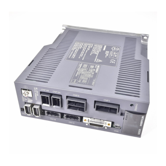
Page 25: Parts Identification
1. FUNCTIONS AND CONFIGURATION 1.7 Parts identification Detailed Name/Application explanation Display The 3-digit, seven-segment LED shows the servo status Section 4.3 and alarm number. Rotary axis setting switch (SW1) Used to set the axis No. of servo amplifier. Section 3.13 Test operation select switch (SW2-1) ON 4E Used to perform the test operation... -
Page 26: Configuration Including Auxiliary Equipment
1. FUNCTIONS AND CONFIGURATION 1.8 Configuration including auxiliary equipment Connecting a servo motor for different axis to the CNP3A or CNP3B connector may CAUTION cause a malfunction. POINT Equipment other than the servo amplifier and the servo motor are optional or recommended products. - Page 27 1. FUNCTIONS AND CONFIGURATION MEMO 1 - 10...
-
Page 28: Installation
2. INSTALLATION 2. INSTALLATION WARNING To prevent electric shock, ground each equipment securely. Stacking in excess of the limited number of products is not allowed. Install the equipment on incombustible material. Installing it directly or close to combustibles will lead to a fire. Install the equipment in a load-bearing place in accordance with this Instruction Manual. - Page 29 2. INSTALLATION (1) Installation of one servo amplifier Control box Control box 40mm or more Wiring Servo amplifier allowance 80mm 10mm 10mm or more or more Bottom 40mm or more (2) Installation of two or more servo amplifiers POINT MR-J3W- B can be installed side-by-side. However, use MR-J3W-44B with the effective load ratio of 90 or less.
-
Page 30: Keep Out Foreign Materials
2. INSTALLATION 2.2 Keep out foreign materials (1) When installing the unit in a control box, prevent drill chips and wire fragments from entering the servo amplifier. (2) Prevent oil, water, metallic dust, etc. from entering the servo amplifier through openings in the control box or a cooling fan installed on the ceiling. -
Page 31: Sscnet Cable
2. INSTALLATION (2) Prohibition of vinyl tape use Migrating plasticizer is used for vinyl tape. Keep the MR-J3BUS M, and MR-J3BUS M-A cables away from vinyl tape because the optical characteristic may be affected. SSCNET cable Cord Cable MR-J3BUS M MR-J3BUS M-A MR-J3BUS M-B : Phthalate ester plasticizer such as DBP and DOP... -
Page 32: Inspection Items
2. INSTALLATION (6) Lateral pressure If lateral pressure is added on optical cable, the optical cable itself distorts, internal optical fiber gets stressed, and then transmission loss will increase. At worst, the breakage of optical cable may occur. As the same condition also occurs at cable laying, do not tighten up optical cable with a thing such as nylon band (TY-RAP). -
Page 33: Parts Having Service Lives
2. INSTALLATION 2.6 Parts having service lives Service lives of the following parts are listed below. However, the service lives vary depending on operating methods and environmental conditions. If any fault is found in the parts, they must be replaced immediately regardless of their service lives. -
Page 34: Signals And Wiring 3 - 1 To
3. SIGNALS AND WIRING 3. SIGNALS AND WIRING Any person who is involved in wiring should be fully competent to do the work. Before wiring or inspection, turn off the power and wait for 15 minutes or more until the charge lamp turns off. Otherwise, an electric shock may occur. In addition, always confirm from the front of the servo amplifier, whether the charge lamp is off or not. -
Page 35: Input Power Supply Circuit
3. SIGNALS AND WIRING 3.1 Input power supply circuit Always connect a magnetic contactor between the power supply and the main circuit power supply (L1, L2, and L3) of the servo amplifier, in order to configure a circuit that shuts down the power supply on the side of the servo amplifier’s power supply. If a magnetic contactor is not connected, continuous flow of a large current may cause a fire when the servo amplifier malfunctions. - Page 36 3. SIGNALS AND WIRING (Note 3) Malfunction Controller forced stop RA1(A-axis) RA2(B-axis) Forced stop (Note 6) Servo amplifier A-axis servo motor (Note 8) CNP1 MCCB (Note 10) (Note 9) CNP3A (Note 5) Power Motor supply CNP2 (Note 1) (Note 2) CN2A Encoder Encoder cable...
- Page 37 3. SIGNALS AND WIRING 3.2 I/O signal connection example 10m or less 10m or less Servo amplifier (1 axis 2 axis) (Note 10) (Note 12) (Note 12) (Note 2) 24VDC DICOM A-axis malfunction ALM-A (Note 11) (Note 14) DOCOM A-axis electromagnetic MBR-A (Note 3, 4) Forced brake interlock (Note 17)
- Page 38 3. SIGNALS AND WIRING Note 1. To prevent an electric shock, always connect the protective earth (PE) terminal (terminal marked ) of the servo amplifier to the protective earth (PE) of the control box. 2. Connect the diode in the correct direction. If it is connected reversely, the servo amplifier will be faulty and will not output signals, disabling the emergency stop and other protective circuits.
- Page 39 3. SIGNALS AND WIRING 3.3 Explanation of power supply system 3.3.1 Signal explanations POINT Keep the manufacturer-setting terminals open. (1) Signal layout and connector application Connector Name Function/Application CNP1 CNP1 Main circuit power supply connector Used to input the main circuit power supply.
- Page 40 3. SIGNALS AND WIRING (2) Detailed description Connection target Abbreviation Description (Application) Supply the following power to L . For the 1-phase 200V to 230VAC power supply, connect the power supply to L , and keep L open. Servo amplifier MR-J3W-22B MR-J3W-77B Main circuit power...
- Page 41 3. SIGNALS AND WIRING 3.3.2 Power-on sequence POINT A voltage, output signal, etc. of analog monitor output may be irregular at power- (1) Power-on procedure 1) Always wire the power supply as shown in above section 3.1 using the magnetic contactor with the main circuit power supply (three-phase: L , single-phase: L ).
- Page 42 3. SIGNALS AND WIRING 3.3.3 CNP1, CNP2, CNP3A, CNP3B wiring method POINT Refer to section 11.5 for the wire sizes used for wiring. Connectors to wire CNP1, CNP2, CNP3A, and CNP3B are not supplied with the servo amplifier. Refer to section 11.1, and purchase the connector set. This section shows the recommended products.
- Page 43 3. SIGNALS AND WIRING (2) Terminal block type (Spring type) (a) Connector Servo amplifier CNP1 CNP2 CNP3A CNP3B Table 3.1 Connectors and applicable wires Applicable Strip-off length No. Connector for Receptacle assembly Open tool Manufacturer wire size [mm] AWG16 to 1) CNP1 03JFAT-SAXGFK-43 11.5...
- Page 44 3. SIGNALS AND WIRING 2) Inserting the wire Insert the open tool as shown in the following figure, and push down the open tool to open the spring hole. The open tool has protrusions for the CNP1 (large size) on one side and those for the others (small size) on another side.
- Page 45 3. SIGNALS AND WIRING 3.4 Connectors and signal arrangements POINT The pin configurations of the connectors are as viewed from the cable connector wiring section. CN5 (USB connector) Refer to section 11.4. LA-A LAR-A LBR-A LB-A LAR-B LA-B LB-B LBR-B CN1A DI1-A DI1-B...
- Page 46 3. SIGNALS AND WIRING 3.5 Signal (device) explanations For the I/O interfaces (symbols in I/O division column in the table), refer to section 3.7.2. In the control mode field of the table The pin No.s in the connector pin No. column are those in the initial status. (1) Connector applications Connector Name...
- Page 47 3. SIGNALS AND WIRING (b) Output device Connector Device Symbol Function/Application pin No. division DO-1 A-axis malfunction ALM-A CN3-11 ALM-A/ALM-B turns off when power is switched off or the protective circuit is activated to shut off the base circuit. Without alarm occurring, ALM-A/ALM-B turns on within about 1.5s after B-axis malfunction ALM-B CN3-24...
- Page 48 3. SIGNALS AND WIRING Connector Device Symbol Function/Application pin No. division A-axis zero speed ZSP-A When using this signal, make it usable by the setting of parameter No.PD07 DO-1 or PD09. ZSP-A/ZSP-B turns on when the servo motor speed is zero speed (50r/min) or less.
- Page 49 3. SIGNALS AND WIRING (c) Output signals Connector Signal name Symbol Function/Application pin No. A-axis encoder A- LA-A CN3-6 Outputs pulses per servo motor revolution set in parameter No.PA15 in the differential phase pulse LAR-A CN3-16 line driver type. In CCW rotation of the servo motor, the encoder B-phase pulse lags the (Differential line encoder A-phase pulse by a phase angle of /2.
- Page 50 3. SIGNALS AND WIRING 3.6 Alarm occurrence timing chart When an alarm has occurred, remove its cause, make sure that the operation signal is not being input, ensure safety, and reset the alarm before restarting operation. Shut off the main circuit power supply when alarms are occurring in both of the A- CAUTION axis and the B-axis.
- Page 51 3. SIGNALS AND WIRING (2) Occurrence of each axis stop alarm Main circuit power Power ON Power ON Control circuit Base circuit Base circuit ON Base circuit ON Base circuit ON Dynamic brake Brake operation Brake operation Servo-on command A-axis Servo-on command Servo-on command (from controller)
-
Page 52: Internal Connection Diagram
3. SIGNALS AND WIRING 3.7 Interfaces 3.7.1 Internal connection diagram Servo amplifier 24VDC DICOM ALM-A DOCOM Approx 5.6k MBR-A (Note 2) DI1-A ALM-B DI2-A MBR-B (Note 2) DI3-A (Note 1) DI1-B LA-A DI2-B Approx LAR-A 5.6k DI3-B LB-A LBR-A Differential line LA-B driver output... - Page 53 3. SIGNALS AND WIRING 3.7.2 Detailed description of interfaces This section provides the details of the I/O signal interfaces (refer to the I/O division in the table) given in section 3.5. Refer to this section and make connection with the external equipment. (1) Digital input interface DI-1 Give a signal with a relay or open collector transistor.
- Page 54 3. SIGNALS AND WIRING (3) Encoder output pulse DO-2 (differential line driver type) (a) Interface Max. output current: 35mA Servo amplifier Servo amplifier LA-A/LA-B LA-A/LA-B Am26LS32 or equivalent (LB-A/LB-B) (LB-A/LB-B) LAR-A/LAR-B LAR-A/LAR-B High-speed photocoupler (LBR-A/LBR-B) (LBR-A/LBR-B) (b) Output pulse Servo motor CCW rotation LA-A/LA-B Time cycle (T) is determined by the settings of parameter No.PA15, PA16 and PC03.
- Page 55 3. SIGNALS AND WIRING 3.7.3 Source I/O interfaces In this servo amplifier, source type I/O interfaces can be used. In this case, all DI-1 input signals and DO-1 output signals are of source type. Perform wiring according to the following interfaces. (1) Digital input interface DI-1 Servo amplifier EM1,...
- Page 56 3. SIGNALS AND WIRING 3.8 Treatment of cable shield external conductor In the case of the CN3 connectors, securely connect the shielded external conductor of the cable to the ground plate as shown in this section and fix it to the connector shell. External conductor Sheath Core...
- Page 57 3. SIGNALS AND WIRING 3.9 SSCNET cable connection POINT Do not see directly the light generated from CN1A CN1B connector of servo amplifier or the end of SSCNET cable. When the light gets into eye, may feel something is wrong for eye. (1) SSCNET cable connection For CN1A connector, connect SSCNET cable connected to controller in host side or servo amplifier.
- Page 58 3. SIGNALS AND WIRING 3) With holding a tab of SSCNET cable connector, make sure to insert it into CN1A CN1B connector of servo amplifier until you hear the click. If the end face of optical cord tip is dirty, optical transmission is interrupted and it may cause malfunctions.
- Page 59 3. SIGNALS AND WIRING 3.10 Connection of servo amplifier and servo motor Connect the servo amplifier power output (U, V, and W) to the servo motor power input (U, V, and W) directly. Do not let a magnetic contactor, etc. intervene. Otherwise, it may cause a malfunction.
- Page 60 3. SIGNALS AND WIRING 3.10.2 Power supply cable wiring diagrams (1) HF-MP series HF-KP series HF-KP series servo motor (a) When cable length is 10m or less 10m or less MR-PWS1CBL M-A1-L MR-PWS1CBL M-A2-L MR-PWS1CBL M-A1-H Servo amplifier Servo motor MR-PWS1CBL M-A2-H CNP3 AWG 19 (red)
- Page 61 3. SIGNALS AND WIRING (2) HF-SP series HC-UP series HC-LP series servo motor POINT Insert a contact in the direction shown in the figure. If inserted in the wrong direction, the contact is damaged and falls off. Soldered part or Soldered part Pin No.1 Pin No.1...
- Page 62 3. SIGNALS AND WIRING 2) When the power supply connector and the electromagnetic brake connector are shared. 50m or less Servo amplifier A-axis servo motor CNP3A 24VDC power (Note 2) supply for 24VDC electromagnetic ALM-A MBR-A brake (Note 3) DOCOM (Note 1) DICOM ALM-A...
- Page 63 3. SIGNALS AND WIRING Encoder connector signal allotment Power supply connector signal allotment Power supply connector signal allotment CM10-R10P MS3102A18-10P CE05-2A22-23PD-B Terminal Terminal Terminal Signal Signal Signal (earth) (earth) View a View b View b (Note) (Note) Note. For the motor with an electromagnetic brake, supply...
- Page 64 3. SIGNALS AND WIRING 3.11 Servo motor with an electromagnetic brake 3.11.1 Safety precautions Configure a electromagnetic brake circuit so that it is activated also by an external emergency stop switch. Contacts must be opened when a Contacts must be opened with malfunction (ALM-A/ALM-B) and when an the emergency stop switch.
- Page 65 3. SIGNALS AND WIRING (1) Connection diagram Servo amplifier A-axis servo motor 24VDC (Note 2) ALM-A MBR-A DOCOM (Note 1) 24VDC power DICOM supply for electromagnetic DICOM ALM-A brake MBR-A ALM-B B-axis servo motor MBR-B ALM-B MBR-B Note 1. Do not use the 24VDC interface power supply for the electromagnetic brake. 2.
- Page 66 3. SIGNALS AND WIRING 3.11.2 Timing charts (1) Servo-on command (from controller) ON/OFF Tb [ms] after the servo-on is switched off, the servo lock is released and the servo motor coasts. If the electromagnetic brake is made valid in the servo lock status, the brake life may be shorter. Therefore, when using the electromagnetic brake in a vertical lift application or the like, set delay time (Tb) to about the same as the electromagnetic brake operation delay time to prevent a drop.
- Page 67 3. SIGNALS AND WIRING (3) Alarm occurrence Dynamic brake Dynamic brake Electromagnetic brake Servo motor speed Electromagnetic brake (10ms) Base circuit Electromagnetic (Note) Electromagnetic brake brake interlock operation delay time (MBR-A/MBR-B) (ON) Alarm (OFF) Note. ON: Electromagnetic brake is not activated. OFF: Electromagnetic brake is activated.
- Page 68 3. SIGNALS AND WIRING (5) Only main circuit power supply off (control circuit power supply remains on) Dynamic brake Dynamic brake (10ms) Electromagnetic brake Servo motor speed Electromagnetic brake (Note 1) 15ms or more Base circuit Electromagnetic (Note 2) brake interlock (MBR-A/MBR-B) Electromagnetic brake (ON)
- Page 69 3. SIGNALS AND WIRING 3.11.3 Wiring diagrams (HF-MP series HF-KP series servo motor) POINT For HF-SP/HC-UP/HC-LP/HF-JP series servo motors, refer to section 3.10.2 (2). (1) When cable length is 10m or less 10m or less MR-BKS1CBL M-A1-L (Note 4) MR-BKS1CBL M-A2-L 24VDC power MR-BKS1CBL...
- Page 70 3. SIGNALS AND WIRING (2) When cable length exceeds 10m When the cable length exceeds 10m, fabricate an extension cable as shown below on the customer side. In this case, the motor brake cable should be within 2m long. Refer to section 11.5 for the wire used for the extension cable. 2m or less MR-BKS1CBL2M-A1-L 50m or less...
- Page 71 3. SIGNALS AND WIRING 3.12 Grounding Ground the servo amplifier and servo motor securely. To prevent an electric shock, always connect the protective earth (PE) terminal WARNING (terminal marked ) of the servo amplifier with the protective earth (PE) of the control box.
- Page 72 3. SIGNALS AND WIRING 3.13 Control axis selection POINT The control axis number set to rotary axis setting switch (SW1) should be the same as the one set to the servo system controller. For changing the setting of the rotary switch, use a flat-blade screwdriver with the blade edge width of 2.1 to 2.3 [mm] and the blade edge thickness of 0.6 to 0.7 [mm].
- Page 73 3. SIGNALS AND WIRING 3.14 Servo motor selection switch (SW3) POINT To prevent an electric shock, wait at least 15 minutes after turning off the power and confirm that the charge lamp is off before changing the servo motor selection switch (SW3) setting.
- Page 74 4. STARTUP 4. STARTUP Do not operate the switches with wet hands. You may get an electric shock. WARNING Before starting operation, check the parameters. Some machines may perform unexpected operation. Take safety measures, e.g. provide covers, to prevent accidental contact of hands and parts (cables, etc.) with the servo amplifier heat sink, regenerative resistor, servo motor, etc.
-
Page 75: Startup Procedure
4. STARTUP 4.1 Switching power on for the first time When switching power on for the first time, follow this section to make a startup. 4.1.1 Startup procedure Setting status check of the servo Check that the setting status matches the servo motor type to be used. (Refer motor selection switch (SW3) to section 3.14.) Check whether the servo amplifier and servo motor are wired correctly using... - Page 76 4. STARTUP 4.1.2 Wiring check (1) Power supply system wiring Before switching on the main circuit and control circuit power supplies, check the following items. (a) Power supply system wiring The power supplied to the power input terminals (L ) of the servo amplifier should satisfy the defined specifications.
- Page 77 4. STARTUP (2) I/O signal wiring (a) The I/O signals should be connected correctly. Use DO forced output to forcibly turn on/off the pins of the CN3 connector. This function can be used to perform a wiring check. In this case, switch on the control circuit power supply only. (b) 24VDC or higher voltage is not applied to the pins of connectors CN3.
- Page 78 4. STARTUP (1) Power on When the main and control circuit power supplies are switched on, "b01" (for the first axis) appears on the servo amplifier display. In the absolute position detection system, first power-on results in the absolute position lost (25.1) alarm and the servo system cannot be switched on.
- Page 79 4. STARTUP 4.3 Servo amplifier display On the servo amplifier display (3-digit, 7-segment display), check the status of communication with the servo system controller at power-on, check the axis number, and diagnose a fault at occurrence of an alarm. 4.3.1 Scrolling display The statuses of the A-axis and the B-axis are displayed alternately.
- Page 80 4. STARTUP 4.3.2 Status display of an axis (1) Display sequence Servo amplifier power ON Waiting for servo system controller power to switch ON (SSCNET communication) Servo system controller power ON (SSCNET communication beginning) Initial data communication with servo system controller (Initialization communication) When alarm warning No.
- Page 81 4. STARTUP (2) Indication list Indication Status Description Power of the servo amplifier was switched on at the condition that the power of servo system controller is OFF. The axis No. set to the servo system controller does not match the axis No. set with the rotary axis setting switch (SW1) of the servo amplifier.
- Page 82 4. STARTUP 4.4 Test operation Before starting actual operation, perform test operation to make sure that the machine operates normally. Refer to section 4.2 for the power on and off methods of the servo amplifier. POINT If necessary, verify controller program by using motor-less operation. Refer to section 4.5.2 for the motor-less operation.
- Page 83 4. STARTUP 4.5 Test operation mode The test operation mode is designed for servo operation confirmation and not for machine operation confirmation. Do not use this mode with the machine. Always use CAUTION the servo motor alone. If an operation fault occurred, use the forced stop (EM1) to make a stop. POINT The content described in this section indicates the environment that servo amplifier and personal computer are directly connected.
- Page 84 4. STARTUP (b) Positioning operation Positioning operation can be performed without using the servo system controller. Use this operation with the forced stop reset. This operation may be used independently of whether the servo is on or off and whether the servo system controller is connected or not. Exercise control on the positioning operation screen of the MR Configurator.
- Page 85 4. STARTUP (2) Operation procedure (a) Switch power off. (b) Set SW2-1 to "UP". Set SW2-1 to "UP" DOWN ON 4E TEST Changing SW2-1 to "UP" while power is on will not start the test operation mode. (c) Switch servo amplifier power on. When initialization is over, the display shows the following screen.
- Page 86 4. STARTUP (b) Alarms The following alarms and warning do not occur. However, the other alarms and warnings occur as when the servo motor is connected. Encoder initial communication error 1 (16. ) Battery cable disconnection warning (92.1) Encoder normal communication error 1 (20. ) Battery warning (9F.1) Encoder normal communication error 2 (21.
- Page 87 4. STARTUP MEMO 4 - 14...
- Page 88 5. PARAMETERS 5. PARAMETERS Never adjust or change the parameter values extremely as it will make operation instable. CAUTION When the fixed values are indicated for any digits of a parameter, never change the values of the digits. POINT When the servo amplifier is connected with the servo system controller, the parameters are set to the values of the servo system controller.
- Page 89 5. PARAMETERS 5.1.1 Parameter list Factory Setting Symbol Name setting Unit (Note 1) (Note 2) PA01 **STY Control mode Each axis 0000h PA02 **REG Regenerative option Common 0000h PA03 *ABS Absolute position detection system Each axis 0000h PA04 *AOP1 Function selection A-1 Common 0000h PA05...
- Page 90 5. PARAMETERS 5.1.2 Parameter write inhibit Parameter Factory Setting Setting Unit setting range Symbol Name Refer to PA19 *BLK Parameter write inhibit Each axis 000Bh the text. POINT Turn off the power and then on again, or reset the controller after setting the parameter to validate the parameter value.
- Page 91 5. PARAMETERS 5.1.3 Selection of control mode Parameter Factory Setting Setting Unit setting range Symbol Name Refer to PA01 **STY Control mode Each axis 0000h the text. POINT Turn off the power and then on again after setting the parameter to validate the parameter value.
- Page 92 5. PARAMETERS 5.1.5 Using absolute position detection system Parameter Factory Setting Setting Unit setting range Symbol Name Refer to PA03 *ABS Absolute position detection system Each axis 0000h the text. POINT Turn off the power and then on again, or reset the controller after setting the parameter to validate the parameter value.
- Page 93 5. PARAMETERS 5.1.7 Auto tuning Parameter Factory Setting Setting Unit setting range Symbol Name Refer to PA08 Auto tuning mode Each axis 0001h the text. PA09 Auto tuning response Each axis 1 to 32 POINT This parameter cannot be used in the torque control mode. Make gain adjustment using auto tuning.
- Page 94 5. PARAMETERS (2) Auto tuning response (parameter No.PA09) If the machine hunts or generates large gear sound, decrease the set value. To improve performance, e.g. shorten the settling time, increase the set value. Guideline for machine Guideline for machine Setting Response Setting Response...
- Page 95 5. PARAMETERS 5.1.9 Selection of servo motor rotation direction Parameter Factory Setting Setting Unit setting range Symbol Name PA14 *POL Rotation direction selection Each axis POINT Turn off the power and then on again, or reset the controller after setting the parameter to validate the parameter value.
- Page 96 5. PARAMETERS (1) For output pulse designation Set " 0 " in parameter No.PC03. Set the number of pulses per servo motor revolution. Output pulse set value [pulses/rev] For instance, set "5600" to Parameter No.PA15, the actually output A/B-phase pulses are as indicated below.
- Page 97 5. PARAMETERS 5.2 Gain/filter parameters (No.PB POINT The parameter whose symbol preceded by * can be validated with the following conditions. * : Turn off the power and then on again, or reset the controller after setting the parameter. The gain/filter parameters (No.PB ) cannot be used in the torque loop mode.
- Page 98 5. PARAMETERS Factory Setting Symbol Name setting Unit (Note 1) (Note 2) PB35 This parameter is not used. Do not change the value. 0.00 PB36 0.00 PB37 PB38 PB39 PB40 PB41 1125 PB42 1125 PB43 0004h PB44 PB45 0000h Note 1. Each axis: Set a value for each of the A-axis and the B-axis. Common: Common parameters for the A-axis and the B-axis.
- Page 99 5. PARAMETERS Factory Setting Symbol Name and function Setting Unit setting range PB05 This parameter is not used. Do not change the value. PB06 Load to motor inertia moment ratio Each Multiplier Used to set the ratio of the load inertia moment to the servo motor shaft inertia axis ( 1) moment.
- Page 100 5. PARAMETERS Factory Setting Symbol Name and function Setting Unit setting range PB13 Machine resonance suppression filter 1 Each 4500 Set the notch frequency of the machine resonance suppression filter 1. axis When the parameter No.PB01 setting is " 0", the setting of this parameter 4500 is ignored.
- Page 101 5. PARAMETERS Factory Setting Symbol Name and function Setting Unit setting range PB17 Automatic setting parameter The value of this parameter is set according to a set value of parameter No.PB06 (Load to motor inertia moment ratio). PB18 Low-pass filter setting Each 3141 rad/s...
- Page 102 5. PARAMETERS Factory Setting Symbol Name and function Setting Unit setting range PB26 *CDP Gain changing selection Each 0000h Refer to Select the gain changing condition. (Refer to section 7.5.) axis Name function column. Gain changing selection Under any of the following conditions, the gains change on the basis of the parameter No.PB29 to PB32 settings.
- Page 103 5. PARAMETERS Factory Setting Symbol Name and function Setting Unit setting range PB34 VRF2B Gain changing vibration suppression control resonance frequency setting Each 100.0 This parameter cannot be used in the speed control mode. axis Set the resonance frequency for vibration suppression control when the gain 100.0 changing is valid.
- Page 104 5. PARAMETERS 5.3 Extension setting parameters (No.PC POINT The parameter whose symbol preceded by * can be validated with the following conditions. * : Turn off the power and then on again, or reset the controller after setting the parameter. **: Turn off the power and then on again after setting the parameter.
- Page 105 5. PARAMETERS 5.3.2 List of details Factory Setting Symbol Name and function Setting Unit setting range PC01 Error excessive alarm level Each This parameter cannot be used in the speed control mode and the torque axis (Note 1) control mode. 1000 Used to set the error excessive alarm level with rotation amount of servo motor.
- Page 106 5. PARAMETERS Factory Setting Symbol Name and function Setting Unit setting range PC06 *COP3 Function selection C-3 Each 0000h Refer to Select the error excessive alarm level setting for parameter No.PC01. axis Name function column. Error excessive alarm level setting selection 0: 1 [rev]unit 1: 0.1...
- Page 107 5. PARAMETERS Factory Setting Symbol Name and function Setting Unit setting range PC11 Analog monitor 1 offset Common 9999 Used to set the offset voltage of the analog monitor 1 (MO1) output. 9999 PC12 Analog monitor 2 offset Common Used to set the offset voltage of the analog monitor 2 (MO2) output. PC13 This parameter is not used.
- Page 108 5. PARAMETERS 5.3.3 Analog monitor The servo status can be output to two channels in terms of voltage. (1) Setting Change the following digits of parameter No.PC09, PC10. Parameter No.PC09 Analog monitor (MO1) output selection (Signal output to across MO1-LG) Analog monitor (MO1) output axis selection 0: A-axis 1: B-axis...
- Page 109 5. PARAMETERS Setting Output item Description Setting Output item Description Current command Speed command CCW direction 8[V] CCW direction 8[V] Max. current command Max. speed (Max. torque command) Max. speed Max. current command (Max. torque command) -8[V] CW direction -8[V] CW direction Droop pulses CCW direction...
- Page 110 5. PARAMETERS (3) Analog monitor block diagram Speed Speed Current Droop pulses Bus voltage command command 2 command Differ- Current Position Speed ential encoder command command Position Speed Current received Servo motor control control control from a controller Encoder Current feedback Differ- ential Position feedback...
-
Page 111: I/O Setting Parameters (No.pd )
5. PARAMETERS 5.4 I/O setting parameters (No.PD POINT The parameter whose symbol preceded by * can be validated with the following conditions. * : Turn off the power and then on again, or reset the controller after setting the parameter. 5.4.1 Parameter list Factory Setting... - Page 112 5. PARAMETERS 5.4.2 List of details Factory Setting Symbol Name and function Setting Unit setting range PD01 This parameter is not used. Do not change the value. 0000h PD02 0000h PD03 0020h PD04 0021h PD05 0022h PD06 0000h PD07 *DO1 Output signal device selection 1 (CN3-12 for A-axis and CN3-25 for B-axis) Each 0005h...
- Page 113 5. PARAMETERS Factory Setting Symbol Name and function Setting Unit setting range PD10 This parameter is not used. Do not change the value. 0000h PD11 0004h PD12 0000h PD13 0000h PD14 *DOP3 Function selection D-3 Each 0000h Refer to Set the ALM-A/ALM-B output signal at warning occurrence. axis Name function...
-
Page 114: Option Setting Parameters (No.po )
5. PARAMETERS 5.5 Option setting parameters (No.Po POINT The parameter whose symbol preceded by * can be validated with the following conditions. * : Turn off the power and then on again, or reset the controller after setting the parameter. **: Turn off the power and then on again after setting the parameter. - Page 115 5. PARAMETERS 5.5.2 List of details Factory Setting Symbol Name and function Setting Unit setting range Po01 *OOP1 Function selection O-1 Common 0000h Refer to Used to set alarms that activate the other axis fault warning (EB). Name function column. The other axis fault warning (EB) activating alarm selection 0: 11, 15, 17, 24 and 32 only...
- Page 116 5. PARAMETERS Factory Setting Symbol Name and function Setting Unit setting range Po04 **OOP2 Function selection O-2 Common 0000h Refer to Name function Special servo motor combination column. 0: Normal combination 1: When using the servo amplifiers and the servo motors as shown below in combination in addition to the normal combination.
- Page 117 5. PARAMETERS MEMO 5 - 30...
- Page 118 6. GENERAL GAIN ADJUSTMENT 6. GENERAL GAIN ADJUSTMENT POINT Consider differences among machines, and adjust the gain. It is recommended that the amount of torque generated from the servo motor in operation be set to 90 the maximum torque of the servo motor. The torque loop mode does not require the gain adjustment.
- Page 119 6. GENERAL GAIN ADJUSTMENT (2) Adjustment sequence and mode usage START Usage Interpolation Used when you want to match made for 2 or more axes? the position gain (PG1) Interpolation mode between 2 or more axes. Normally not used for other Operation purposes.
- Page 120 6. GENERAL GAIN ADJUSTMENT 6.2 Auto tuning 6.2.1 Auto tuning mode The servo amplifier has a real-time auto tuning function which estimates the machine characteristic (load inertia moment ratio) in real time and automatically sets the optimum gains according to that value. This function permits ease of gain adjustment of the servo amplifier.
- Page 121 6. GENERAL GAIN ADJUSTMENT 6.2.2 Auto tuning mode basis The block diagram of real-time auto tuning is shown below. Load inertia Automatic setting moment Encoder Loop gains Command Current Servo PG1,VG1 control motor PG2,VG2,VIC Current feedback Real-time auto Position/speed Set 0 or 1 to turn on. tuning section feedback Load inertia...
- Page 122 6. GENERAL GAIN ADJUSTMENT 6.2.3 Adjustment procedure by auto tuning Since auto tuning is made valid before shipment from the factory, simply running the servo motor automatically sets the optimum gains that match the machine. Merely changing the response level setting value as required completes the adjustment.
- Page 123 6. GENERAL GAIN ADJUSTMENT 6.2.4 Response level setting in auto tuning mode Set the response (The first digit of parameter No.PA09) of the whole servo system. As the response level setting is increased, the track ability and settling time for a command decreases, but a too high response level will generate vibration.
- Page 124 6. GENERAL GAIN ADJUSTMENT 6.3 Manual mode 1 (simple manual adjustment) If you are not satisfied with the adjustment of auto tuning, you can make simple manual adjustment with three parameters. POINT If machine resonance occurs, machine resonance suppression filter (parameter No.PB01, PB13 to PB16) may be used to suppress machine resonance.
- Page 125 6. GENERAL GAIN ADJUSTMENT (c) Adjustment description 1) Speed loop gain (parameter No.PB09) This parameter determines the response level of the speed control loop. Increasing this value enhances response but a too high value will make the mechanical system liable to vibrate. The actual response frequency of the speed loop is as indicated in the following expression.
- Page 126 6. GENERAL GAIN ADJUSTMENT (2) For position control (a) Parameters The following parameters are used for gain adjustment. Parameter No. Abbreviation Name PB06 Load to motor inertia moment ratio PB07 Model loop gain PB08 Position loop gain PB09 Speed loop gain PB10 Speed integral compensation (b) Adjustment procedure...
- Page 127 6. GENERAL GAIN ADJUSTMENT (c) Adjustment description 1) Speed loop gain (VG2: parameter No.PB09) This parameter determines the response level of the speed control loop. Increasing this value enhances response but a too high value will make the mechanical system liable to vibrate. The actual response frequency of the speed loop is as indicated in the following expression.
- Page 128 6. GENERAL GAIN ADJUSTMENT 6.4 Interpolation mode The interpolation mode is used to match the position loop gains of the axes when performing the interpolation operation of servo motors of two or more axes for an X-Y table or the like. In this mode, manually set the model loop gain that determines command track ability.
- Page 129 6. GENERAL GAIN ADJUSTMENT MEMO 6 - 12...
- Page 130 7. SPECIAL ADJUSTMENT FUNCTIONS 7. SPECIAL ADJUSTMENT FUNCTIONS POINT The functions given in this chapter need not be used generally. Use them if you are not satisfied with the machine status after making adjustment in the methods in chapter 6. If a mechanical system has a natural resonance point, increasing the servo system response level may cause the mechanical system to produce resonance (vibration or unusual noise) at that resonance frequency.
- Page 131 7. SPECIAL ADJUSTMENT FUNCTIONS Machine resonance point Mechanical system response level Frequency Notch depth Frequency Parameter No.PB01, Parameter No.PB15, PB13, PB14 PB16 (2) Parameters (a) Machine resonance suppression filter 1 (parameter No.PB13, PB14) Set parameter No.PB01 to " 2". Set the notch frequency, notch depth and notch width of the machine resonance suppression filter 1 (parameter No.PB13, PB14) (b) Machine resonance suppression filter 2 (parameter No.PB15, PB16) Set parameter No.PB16 to "...
- Page 132 7. SPECIAL ADJUSTMENT FUNCTIONS 7.3 Vibration suppression control manual mode Measure work side vibration and device shake with the machine analyzer or external measuring instrument, and set the vibration suppression control vibration frequency (parameter No.PB19) and vibration suppression control resonance frequency (parameter No.PB20) to set vibration suppression control manually. (1) Operation Vibration suppression control is used to further suppress machine side vibration, such as workpiece end vibration and base shake.
- Page 133 7. SPECIAL ADJUSTMENT FUNCTIONS (b) When vibration can be confirmed using monitor signal or external measuring instrument Motor side vibration External acceleration pick signal, etc. (Droop pulses) Position command frequency Vibration suppression control Vibration cycle [Hz] vibration frequency Vibration cycle [Hz] Vibration suppression control resonance frequency Set the same value.
- Page 134 7. SPECIAL ADJUSTMENT FUNCTIONS 7.4 Low-pass filter (1) Function When a ball screw or the like is used, resonance of high frequency may occur as the response level of the servo system is increased. To prevent this, the low-pass filter is factory-set to be valid for a torque command. The filter frequency of this low-pass filter is automatically adjusted to the value in the following expression.
- Page 135 7. SPECIAL ADJUSTMENT FUNCTIONS 7.5.2 Function block diagram The valid loop gains PG2, VG2, VIC, GD2, VRF1 and VRF2 of the actual loop are changed according to the conditions selected by gain changing selection CDP (parameter No.PB26) and gain changing condition CDS (parameter No.PB27).
- Page 136 7. SPECIAL ADJUSTMENT FUNCTIONS 7.5.3 Parameters When using the gain changing function, always set " 3" in parameter No.PA08 (auto tuning) to choose the manual mode of the gain adjustment modes. The gain changing function cannot be used in the auto tuning mode.
- Page 137 7. SPECIAL ADJUSTMENT FUNCTIONS (1) Parameters No.PB06 to PB10 These parameters are the same as in ordinary manual adjustment. Gain changing allows the values of load to motor inertia moment ratio, position loop gain, speed loop gain and speed integral compensation to be changed.
- Page 138 7. SPECIAL ADJUSTMENT FUNCTIONS 7.5.4 Gain changing procedure This operation will be described by way of setting examples. (1) When you choose changing by input device (a) Setting Parameter No. Abbreviation Name Setting Unit PB07 Model loop gain rad/s Multiplier PB06 Load to motor inertia moment ratio ( 1)
- Page 139 7. SPECIAL ADJUSTMENT FUNCTIONS (2) When you choose changing by droop pulses In this case, gain changing vibration suppression control cannot be used. (a) Setting Parameter No. Abbreviation Name Setting Unit PB07 Model loop gain rad/s Multiplier PB06 Load to motor inertia moment ratio ( 1) PB08 Position loop gain...
-
Page 140: Troubleshooting
8. TROUBLESHOOTING 8. TROUBLESHOOTING POINT When an alarm with "Each axis" indicated in the "Stop method" column occurs, the servo motor in the non-alarm-occurring axis can continue running. If an alarm/warning has occurred, refer to this chapter and remove its cause. 8.1 Alarms and warning list When an error occurs during operation, the corresponding alarm or warning is displayed. - Page 141 8. TROUBLESHOOTING Deceleration method when Alarm deactivation Detection Stop an alarm occurs (Note 5) Display Name method method MR-J3W- MR-J3W- Power (Note 3) (Note 4) Error reset CPU reset 22B to MR- 0303BN6 OFF ON J3W-1010B (Note 6) Overload 1 (Note 1) (Note 1) (Note 1)
- Page 142 8. TROUBLESHOOTING 8.2 Troubleshooting at power on POINT Refer to section 15.4.2 for MR-J3W-0303BN6. When the servo system does not boot and system error occurs at power on of the servo system controller, improper boot of the servo amplifier might be the cause. Check the display of the servo amplifier, and take actions according to this section.
-
Page 143: Remedies For Alarms
8. TROUBLESHOOTING 8.3 Remedies for alarms When any alarm has occurred, eliminate its cause, ensure safety, then reset the alarm, and restart operation. Otherwise, injury may occur. If an absolute position erase (25.1) occurred, always make home position setting CAUTION again. - Page 144 8. TROUBLESHOOTING Alarm No.10 Name: Undervoltage Stop method: All axes stop Voltage of the control circuit power has dropped. Alarm description Voltage of the main circuit power has dropped. Display Name Cause Checkpoint Finding Action 10.1 Voltage drop in Connector for the control Check the connector of Disconnected or Connect properly.
- Page 145 8. TROUBLESHOOTING Alarm No.11 Name: Switch setting error Stop method: All axis stop Rotary axis setting switch is incorrectly set. Alarm description DIP switch is incorrectly set. Servo motor selection switch is incorrect set. Display Name Cause Checkpoint Finding Action 11.1 Rotary switch (1) Rotary switch for axis...
- Page 146 8. TROUBLESHOOTING Alarm No.12 Name: Memory error 1 (RAM) Stop method: All axes stop Interior part of the servo amplifier (CPU) is faulty. Alarm description Interior part of the servo amplifier (custom IC) is faulty. Display Name Cause Checkpoint Finding Action 12.1 CPU built-in RAM...
- Page 147 8. TROUBLESHOOTING Alarm No.15 Name: Memory error 2 (EEP-ROM) Stop method: All axes stop Alarm description Interior part of the servo amplifier (EEP-ROM) is faulty. Display Name Cause Checkpoint Finding Action 15.1 EEP-ROM error (1) EEP-ROM operates Unplug all cables except Reproduced.
- Page 148 8. TROUBLESHOOTING Alarm No.16 Name: Encoder initial communication error 1 Stop method: Corresponding axis stops Alarm description Error occurs in the communication between the encoder and the servo amplifier. Display Name Cause Checkpoint Finding Action 16.3 Encoder receive When using only one Check if parameter No.
- Page 149 8. TROUBLESHOOTING Alarm No.17 Name: Board error Stop method: All axes stop Alarm description Interior part of the servo amplifier is faulty. Display Name Cause Checkpoint Finding Action 17.1 AD converter (1) Current detection circuit Check the reproducibility Reproduced. Replace the servo error error of error at power on of the...
- Page 150 8. TROUBLESHOOTING Alarm No.1A Name: Motor combination error Stop method: Corresponding axis stops Alarm description Combination of servo amplifier and servo motor is incorrect. Display Name Cause Checkpoint Finding Action 1A.1 Motor Servo amplifier is Check the model name of Combination is Use in the right combination error...
- Page 151 8. TROUBLESHOOTING Alarm No.20 Name: Encoder normal communication error 1 Stop method: Corresponding axis stops Alarm description Error is found in the communication between the encoder and the servo amplifier. Display Name Cause Checkpoint Finding Action 20.1 Encoder receive (1) Encoder cable is faulty. Check the shield.
- Page 152 8. TROUBLESHOOTING Alarm No.21 Name: Encoder normal communication error 2 Stop method: Corresponding axis stops Alarm description Error is found in the encoder data. Display Name Cause Checkpoint Finding Action 21.1 Encoder data High acceleration rate is Decrease the loop gain, Not reproduced.
- Page 153 8. TROUBLESHOOTING Alarm No.25 Name: Absolute position erase Stop method: Corresponding axis stops Error is found in absolute position data. Alarm description Power is switched on for the first time in the absolute position detection system. Display Name Cause Checkpoint Finding Action 25.1...
- Page 154 8. TROUBLESHOOTING Alarm No.31 Name: Overspeed Stop method: Corresponding axis stops Alarm description Servo motor speed exceeds the instantaneous permissible speed. Display Name Cause Checkpoint Finding Action 31.1 Abnormal motor The command from the The command from the Permissible rotation Review the operation speed controller is excessive.
- Page 155 8. TROUBLESHOOTING Alarm No.32 Name: Overcurrent Stop method: All axes stop Alarm description Current that flew is the permissible current of the servo amplifier or higher. Display Name Cause Checkpoint Finding Action 32.1 Overcurrent (1) Servo amplifier is faulty. Check if this alarm Appears.
- Page 156 8. TROUBLESHOOTING Alarm No.33 Name: Overvoltage Stop method: All axes stop Alarm description Bus voltage exceeds 400VDC. Display Name Cause Checkpoint Finding Action 33.1 Main circuit Although the regenerative Check the parameter No. Setting is incorrect. Correct the setting. voltage error option is used, the PA02 setting.
- Page 157 8. TROUBLESHOOTING Alarm No.34 Name: SSCNET receive error 1 Stop method: Corresponding axis stops Alarm description SSCNET communication error (Continuous communication error for 3.5ms) Display Name Cause Checkpoint Finding Action 34.1 SSCNET receive (1) SSCNET cable is Check the SSCNET Disconnected.
- Page 158 8. TROUBLESHOOTING Alarm No.34 Name: SSCNET receive error 1 Stop method: Corresponding axis stops Alarm description SSCNET communication error (Continuous communication error for 3.5ms) Display Name Cause Checkpoint Finding Action 34.3 Communication (1) SSCNET cable is Examine checkpoints described in the alarm display "34.1". data error disconnected.
- Page 159 8. TROUBLESHOOTING Alarm No.36 Name: SSCNET receive error 2 Stop method: Corresponding axis stops Alarm description SSCNET communication error (Continuous communication error for about 70ms.) Display Name Cause Checkpoint Finding Action 36.1 Continuous (1) SSCNET cable is Check the cable Disconnected.
- Page 160 8. TROUBLESHOOTING Alarm No.45 Name: Main circuit device overheat Stop method: All axes stop Alarm description Inside of the servo amplifier overheats. Display Name Cause Checkpoint Finding Action 45.1 Main circuit (1) Surrounding air Check that surrounding Surrounding air Lower the surrounding abnormal temperature is over 55 .
- Page 161 8. TROUBLESHOOTING Alarm No.47 Name: Cooling fan error Stop method: All axes stop Cooling fan speed of the servo amplifier is decreased. Alarm description Cooling fan speed drops to the alarm level or lower. Display Name Cause Checkpoint Finding Action 47.1 Cooling fan stop (1) Foreign matter is caught...
- Page 162 8. TROUBLESHOOTING Alarm No.50 Name: Overload 1 Stop method: Corresponding axis stops Alarm description Load exceeds overload protection characteristic of servo amplifier. Display Name Cause Checkpoint Finding Action 50.2 Thermal overload (1) Machine struck Check if the machine Machine struck. Review the operation error 2 during something.
- Page 163 8. TROUBLESHOOTING Alarm No.50 Name: Overload 1 Stop method: Corresponding axis stops Alarm description Load exceeds overload protection characteristic of servo amplifier. Display Name Cause Checkpoint Finding Action 50.4 Thermal overload Electromagnetic brake is Check if the Activated. Review the wiring error 1 during a activated.
- Page 164 8. TROUBLESHOOTING Alarm No.50 Name: Overload 1 Stop method: Corresponding axis stops Alarm description Load exceeds overload protection characteristic of servo amplifier. Display Name Cause Checkpoint Finding Action 50.6 Thermal overload (1) Machine struck Examine checkpoints described in the alarm display "50.5". error 4 during a something.
- Page 165 8. TROUBLESHOOTING Alarm No.52 Name: Error excessive Stop method: Corresponding axis stops The droop pulses existing between the model position and the actual servo motor position exceeds the Alarm description alarm level. Display Name Cause Checkpoint Finding Action 52.3 Excess droop (1) Power cable is cut.
- Page 166 8. TROUBLESHOOTING Alarm No. 8A Name: USB communication time-out error Stop method: All axes stop Communication between the servo amplifier and a communication device (PC, etc.) stops for the Alarm description specified time or longer. Display Name Cause Checkpoint Finding Action 8A.1 (1) Communication...
- Page 167 8. TROUBLESHOOTING Alarm No. 8E Name: USB communication error Stop method: All axes stop Alarm description USB communication error occurs between the servo amplifier and a communication device (PC, etc.) Display Name Cause Checkpoint Finding Action 8E.4 (1) Command not in the Check the command Command not in the Modify the send...
-
Page 168: Remedies For Warnings
8. TROUBLESHOOTING 8.4 Remedies for warnings If an absolute position counter warning (E3. ) occurred, always make home position CAUTION setting again. Not doing so may cause unexpected operation. POINT When any of the following alarms has occurred, do not resume operation by switching power of the servo amplifier OFF/ON repeatedly. - Page 169 8. TROUBLESHOOTING Stop method: Axes can operate (detected at Warning No. 92 Name: Battery cable disconnection warning the corresponding axis). Warning description Battery voltage of absolute position detection system is low. Display Name Cause Checkpoint Finding Action 92.1 Encoder battery (1) Battery cable has Check the battery cable.
- Page 170 8. TROUBLESHOOTING Stop method: Axes can operate (warning Warning No. E0 Name: Excessive regeneration warning detected at both axes) There is a possibility that regenerative power may exceed permissible regenerative power of built-in Warning description regenerative resistor or regenerative option. Display Name Cause...
- Page 171 8. TROUBLESHOOTING Stop method: Axes can operate (detected at Warning No. E3 Name: Absolute position counter warning the corresponding axis) The multi-revolution counter value of the absolute position encoder exceeds the maximum revolution Warning description range. Absolute position encoder pulses are faulty. Display Name Cause...
- Page 172 8. TROUBLESHOOTING Warning No. E7 Name: Controller forced stop warning Stop method: All axes stop Warning description Forced stop signal is input from the servo system controller. Display Name Cause Checkpoint Finding Action E7.1 Controller forced (1) Forced stop signal was Check if the servo system In forced stop status.
- Page 173 8. TROUBLESHOOTING Stop method: All axes stop (warning detected Warning No. EB Name: The other axis fault warning at both axes). Warning description In the other axis, alarm demanding all axes stop (11. , 15. , 17. , 24. and 32. ) is output. Display Name Cause...
- Page 174 9. OUTLINE DRAWINGS 9. OUTLINE DRAWINGS 9.1 Servo amplifier (1) MR-J3W-22B/MR-J3W-44B [Unit: mm] 2- 6 mounting hole Approx. 80 CNP1 CNP2 (Note) CNP3A Cooling fan CNP3B air intake Note. Cooling fan is equipped only with MR-J3W-44B. It is not necessary to drill air holes on the control box surface for the cooling fan.
- Page 175 9. OUTLINE DRAWINGS (2) MR-J3W-77B/MR-J3W-1010B [Unit: mm] 2- 6 mounting hole Approx. 80 CNP1 CNP2 CNP3A CNP3B Cooling fan air intake Mass: 2.3 [kg] (5.07 [lb]) Terminal signal layout CNP1 Approx. 100 CNP2 4-M5 screw CNP3A Approx. 6 Approx. 6 CNP3B Mounting hole process drawing PE( )
- Page 176 9. OUTLINE DRAWINGS 9.2 Connector (1) CN1A CN1B connector [Unit: mm] F0-PF2D103 F0-PF2D103-S 17.6 17.6 20.9 20.9 (2) Miniature delta ribbon (MDR) system (3M) (a) One-touch lock type [Unit: mm] Logo etc, are indicated here. 12.7 Each type of dimension Connector Shell kit 10126-3000PE...
- Page 177 9. OUTLINE DRAWINGS (b) Jack screw M2.6 type This is not available as option. [Unit: mm] Logo etc, are indicated here. 12.7 Each type of dimension Connector Shell kit 10126-3000PE 10326-52A0-008 25.8 37.2 14.0 10.0 12.0 31.3 (3) SCR connector system (3M) Receptacle: 36210-0100PL Shell kit : 36310-3200-008 39.5...
-
Page 178: Characteristics
10. CHARACTERISTICS 10. CHARACTERISTICS 10.1 Overload protection characteristics An electronic thermal relay is built in the servo amplifier to protect the servo motor, the servo amplifier and the servo motor power lines from overloads. Overload 1 alarm (50. ) occurs if overload operation performed is above the electronic thermal relay protection curve shown in any of Figs 10.1. - Page 179 10. CHARACTERISTICS 10.2 Power supply equipment capacity and generated loss (1) Amount of heat generated by the servo amplifier Table 10.1 indicates servo amplifiers' power supply capacities and losses generated under rated load. For thermal design of an enclosure, use the values in Table 10.1 in consideration for the worst operating conditions.
- Page 180 10. CHARACTERISTICS (2) Heat dissipation area for enclosed servo amplifier The enclosed control box (hereafter called the control box) which will contain the servo amplifier should be designed to ensure that its temperature rise is within 10 at the ambient temperature of 40 . (With a 5 (41 ) safety margin, the system should operate within a maximum 55 (131 ) limit.) The necessary enclosure heat dissipation area can be calculated by Equation 10.1.
-
Page 181: Dynamic Brake Characteristics
10. CHARACTERISTICS 10.3 Dynamic brake characteristics POINT Dynamic brake operates at occurrence of alarm, servo forced stop warning (E6.1), and controller forced stop warning (E7.1), and when power is turned off. Do not use dynamic brake to stop in a normal operation as it is the function to stop in emergency. - Page 182 10. CHARACTERISTICS (2) Dynamic brake time constant The following shows necessary dynamic brake time constant for the equations (10.2). 1000 2000 3000 4000 5000 6000 1000 2000 3000 4000 5000 6000 Speed [r/min] Speed [r/min] HF-MP series HF-KP series 500 1000 1500 2000 2500 3000 1000 1500 2000...
- Page 183 10. CHARACTERISTICS 10.3.2 The dynamic brake at the load inertia moment Use the dynamic brake under the load inertia moment ratio indicated in the following table. If the load inertia moment is higher than this value, the dynamic brake may burn. If there is a possibility that the load inertia moment may exceed the value, contact your local sales office.
- Page 184 10. CHARACTERISTICS 10.5 Inrush currents at power-on of main circuit and control circuit The following table indicates the inrush currents (reference data) that will flow when the maximum permissible voltage (253VAC) is applied at the power supply capacity of 2500kVA and the wiring length of 1m. Inrush currents (A Servo amplifier Main circuit power supply (L...
- Page 185 10. CHARACTERISTICS MEMO 10 - 8...
-
Page 186: Cable/Connector Sets
11. OPTIONS AND AUXILIARY EQUIPMENT 11. OPTIONS AND AUXILIARY EQUIPMENT Before wiring or inspection, turn off the power and wait for 15 minutes or more until the charge lamp turns off. Otherwise, an electric shock may occur. In addition, WARNING always confirm from the front of the servo amplifier, whether the charge lamp is off or not. - Page 187 11. OPTIONS AND AUXILIARY EQUIPMENT Servo amplifier CNP1 Direct connection (cable length 10m or less, IP65) 20)21)22)23) CNP2 Junction type (cable length more than10m, IP20) CNP3A 26)27) 24)25) CNP3B (Note) CN2A 48)19)50)51) CN2B 52)53)54)55) (Note) Junction type (cable length more than10m, IP65) 31)32) 29)30) 18)19)
- Page 188 11. OPTIONS AND AUXILIARY EQUIPMENT (Note 1) Product Model Description Application SSCNET MR-J3BUS M Connector: PF-2D103 Connector: PF-2D103 Inside panel cable Cable length: 0.15 to 3m (Japan Aviation Electronics (Japan Aviation Electronics standard cord (Refer to section 11.1.5.) Industry, Ltd.) Industry, Ltd.) SSCNET MR-J3BUS M-A...
- Page 189 11. OPTIONS AND AUXILIARY EQUIPMENT (Note 1) Product Model Description Application Motor power MR-PWS1CBL M-A2-L IP65 supply cable Cable length: 2 5 10m Opposite-to- load side lead Power supply connector EN compliant Motor power MR-PWS1CBL M-A2-H IP65 HF-MP series supply cable Cable length: 2 5 10m HF-KP series Opposite-to-...
- Page 190 11. OPTIONS AND AUXILIARY EQUIPMENT (Note 1) Product Model Description Application Encoder MR-J3ENCBL M-A1-L IP65 Encoder connector cable Cable length: 2 5 10m Load side lead HF-MP series Encoder MR-J3ENCBL M-A1-H IP65 HF-KP series cable Cable length: 2 5 10m Load side lead Long bending Refer to section 11.1.2 (1) for details.
- Page 191 11. OPTIONS AND AUXILIARY EQUIPMENT (Note 1) Product Model Description Application Encoder MR-J3ENSCBL IP67 cable Cable length: Standard flex 2 5 10 20 30m life Encoder MR-J3ENSCBL Refer to section 11.1.2 (5) for details. IP67 cable Cable length: Long bending 2 5 10 20 30 40 life Encoder...
- Page 192 11. OPTIONS AND AUXILIARY EQUIPMENT (Note 1) Product Model Description Application Encoder MR-J3SCNS-S06 IP67 connector (Note 2) For HF-SP/HC-UP/HC-LP/HF-JP series Refer to section 11.1.2 (5) for details. Encoder MR-J3SCNSA-S06 IP67 connector (Note 2) For HF-SP/HC-UP/HC-LP/HF-JP series Refer to section 11.1.2 (5) for details. Brake MR-BKCNS1-S06 Straight plug: CM10-SP2S-VP-L...
- Page 193 11. OPTIONS AND AUXILIARY EQUIPMENT (Note 1) Product Model Description Application Connector MR-J3WCNP3-DL Use this connector set to directly connect to the servo amplifier using Quantity: 1 MR-PWS1CBL M- . For thin wire For CNP3A/CNP3B Receptacle housing: F35FDC-04V-K Receptacle contact: LF3F-41GF-P2.0 Connector MR-J3WCNP3-DL-20P Quantity: 20...
- Page 194 11. OPTIONS AND AUXILIARY EQUIPMENT 11.1.2 Encoder cable/connector sets (1) MR-J3ENCBL M-A1-L/H MR-J3ENCBL M-A2-L/H These cables are encoder cables for the HF-MP HF-KP series servo motors. The numerals in the Cable Length field of the table are the symbols entered in the part of the cable model.
- Page 195 11. OPTIONS AND AUXILIARY EQUIPMENT (b) Cable internal wiring diagram MR-J3ENCBL2M-A1-L/H MR-J3ENCBL5M-A1-L/H MR-J3ENCBL10M-A1-L/H MR-J3ENCBL2M-A2-L/H MR-J3ENCBL5M-A2-L/H MR-J3ENCBL10M-A2-L/H Encoder side Servo amplifier connector side connector Plate (2) MR-EKCBL M-L/H POINT The following encoder cables are of four-wire type. When using any of these encoder cables, set parameter No.PC04 to "1 "...
- Page 196 11. OPTIONS AND AUXILIARY EQUIPMENT (a) Connection of servo amplifier and servo motor Servo amplifier MR-EKCBL CN2A MR-J3JCBL03M-A2-L MR-EKCBL Cable length: 0.3m CN2B Servo motor HF-MP HF-KP Cable model 1) For CN2 connector 2) For encoder connector MR-EKCBL M-L Receptacle: 36210-0100PL Connector set: 54599-1019 (Molex) Housing: 1-172161-9 Shell kit: 36310-3200-008...
- Page 197 11. OPTIONS AND AUXILIARY EQUIPMENT (b) Internal wiring diagram MR-EKCBL20M-L MR-EKCBL30M-L Servo amplifier side Encoder side Servo amplifier side Encoder side Plate (Note) CONT Plate (Note) MR-EKCBL20M-H MR-EKCBL30M-H MR-EKCBL40M-H Servo amplifier side Encoder side MR-EKCBL50M-H Servo amplifier side Encoder side Plate (Note) CONT...
- Page 198 11. OPTIONS AND AUXILIARY EQUIPMENT (c) When fabricating the encoder cable When fabricating the cable, prepare the following parts and tool, and fabricate it according to the wiring diagram in (b). Refer to section 11.5 for the specifications of the used cable. Parts/tool Description Connector set...
- Page 199 11. OPTIONS AND AUXILIARY EQUIPMENT (a) Connection of servo amplifier and servo motor Servo amplifier MR-J3JCBL03M-A1-L Servo motor HF-MP HF-KP MR-EKCBL M-L/-H CN2A MR-J3JCBL03M-A2-L CN2B Servo motor HF-MP HF-KP Cable model 1) Junction connector 2) For encoder connector MR-J3JCBL03M-A1-L Housing: 1-172169-9 Connector: 2174053-1 Contact: 1473226-1 Crimping tool for ground clip: 1596970-1...
- Page 200 11. OPTIONS AND AUXILIARY EQUIPMENT (4) MR-J3JSCBL03M-A1-L MR-J3JSCBL03M-A2-L A servo amplifier and a servo motor cannot be connected by these cables alone. The servo motor side encoder cable (MR-J3ENSCBL M-L/H) is required. Cable model Cable length IP rating Bending life Application For HF-MP HF-KP servo motor Load side lead...
- Page 201 11. OPTIONS AND AUXILIARY EQUIPMENT (b) Internal wiring diagram MR-J3JSCBL03M-A1-L MR-J3JSCBL03M-A2-L Junction Encoder side connector connector CONT CONT (5) MR-J3ENSCBL M-L(-S06) MR-J3ENSCBL M-H(-S06) These cables are detector cables for HF-SP HC-UP HC-LP HF-JP Series servo motors. The number in the cable length column of the table indicates the symbol filling the square in the cable model.
- Page 202 11. OPTIONS AND AUXILIARY EQUIPMENT Cable model 1) For CNP2A/CNP2B connector 2) For encoder connector MR-J3ENSCBL M- Receptacle: 36210-0100PL Shell kit: 36310-3200-008 Plug (DDK) Cable Bending life (3M) length Straight plug Socket contact CMV1-#22ASC-C1-100 Long (Note) Signal layout 10m or Applicable wire size: AWG24 to bending life shorter...
- Page 203 11. OPTIONS AND AUXILIARY EQUIPMENT (b) Internal wiring diagram MR-J3ENSCBL20M-H (-S06) MR-J3ENSCBL2M-L (-S06) /H (-S06) MR-J3ENSCBL30M-H (-S06) MR-J3ENSCBL5M-L (-S06) /H (-S06) MR-J3ENSCBL20M-L (-S06) MR-J3ENSCBL40M-H (-S06) MR-J3ENSCBL10M-L (-S06) /H (-S06) MR-J3ENSCBL30M-L (-S06) MR-J3ENSCBL50M-H (-S06) Servo amplifier Encoder side Servo amplifier Encoder side Servo amplifier Encoder side side connector...
- Page 204 11. OPTIONS AND AUXILIARY EQUIPMENT (c) When fabricating the encoder cable When fabricating the cable, prepare the following parts and tool, and fabricate it according to the wiring diagram in (b). Refer to section 11.5 for the specifications of the used cable. Parts/Tool Description (Connector set)
- Page 205 11. OPTIONS AND AUXILIARY EQUIPMENT 11.1.3 Motor power supply cables These cables are motor power supply cables for the HF-MP HF-KP series servo motors. The numerals in the Cable length field of the table are the symbols entered in the part of the cable model.
- Page 206 11. OPTIONS AND AUXILIARY EQUIPMENT 11.1.4 Motor brake cables These cables are motor brake cables for the HF-MP HF-KP series servo motors. The numerals in the Cable length field of the table are the symbols entered in the part of the cable model. The cables of the lengths with the symbols are available.
- Page 207 11. OPTIONS AND AUXILIARY EQUIPMENT 11.1.5 SSCNET cable POINT Do not see directly the light generated from CN1A CN1B connector of servo amplifier or the end of SSCNET cable. When the light gets into eye, you may feel something is wrong for eye. (1) Model explanations Numeral in the column of cable length on the table is a symbol put in the part of cable model.
- Page 208 11. OPTIONS AND AUXILIARY EQUIPMENT (3) Outline drawings (a) MR-J3BUS015M [Unit: mm] (6.7) (15) (13.4) (37.65) Protective tube (20.9) (b) MR-J3BUS03M to MR-J3BUS3M Refer to the table shown in (1) of this section for cable length (L). [Unit: mm] Protective tube (Note) (100) (100)
- Page 209 11. OPTIONS AND AUXILIARY EQUIPMENT 11.1.6 Battery cable (1) Model explanations The numbers in the Cable length column in the table go into of the cable model names. Cables with the lengths of the numbers are available. Cable length Cable model Fiex life Application / Remark 0.3m...
- Page 210 11. OPTIONS AND AUXILIARY EQUIPMENT 11.2 Regenerative options The specified combinations of regenerative options and servo amplifiers may only be CAUTION used. Otherwise, a fire may occur. (1) Combination and regenerative power The power values in the table are resistor-generated powers and not rated powers. Regenerative power [W] Servo amplifier Built-in regenerative...
- Page 211 11. OPTIONS AND AUXILIARY EQUIPMENT (2) Selection of the regenerative option Use the following method when regeneration occurs continuously in vertical motion applications or when it is desired to make an in-depth selection of the regenerative option. (a) Regenerative energy calculation Use the following table to calculate the regenerative energy.
- Page 212 11. OPTIONS AND AUXILIARY EQUIPMENT (b) Losses of servo motor and servo amplifier in regenerative mode The following table lists the efficiencies and other data of the servo motor and servo amplifier in the regenerative mode. Servo amplifier Inverse efficiency [ ] Capacitor charging [J] MR-J3W-22B MR-J3W-44B...
- Page 213 11. OPTIONS AND AUXILIARY EQUIPMENT (3) Parameter setting Set parameter No.PA02 according to the option to be used. Parameter No.PA02 Selection of regenerative option 00: Regenerative option is not used (built-in regenerative resistor is used) 0D: MR-RB14 0E: MR-RB34 10: MR-RB3B (4) Connection of the regenerative option POINT For the sizes of wires used for wiring, refer to section 11.5.
- Page 214 11. OPTIONS AND AUXILIARY EQUIPMENT (5) Outline drawing (a) MR-RB14 [Unit: mm] Terminal block 6 mounting hole Applicable wire size: 2 to 2.5mm (AWG24 to AWG12) Tightening torque: 0.5 to 0.6 [N m] (4 to 5 [lb in]) Mounting screw Screw size: M5 Tightening torque: 3.24 [N m] (28.7 [lb in]) Mass: 1.1 [kg] (2.4 [lb])
-
Page 215: Mr-Btcase Battery Case And Mr-Bat Battery
11. OPTIONS AND AUXILIARY EQUIPMENT 11.3 MR-BTCASE battery case and MR-BAT battery POINT Refer to appendix 5 and 6 for battery transportation and the new EU Battery Directive. Always install eight MR-BAT batteries to an MR-BTCASE battery case. These are used to configure an absolute position detection system. An MR-BTCASE battery case is a case that stores eight MR-BAT batteries by connector connections. -
Page 216: Mr Configurator
11. OPTIONS AND AUXILIARY EQUIPMENT 11.4 MR Configurator The MR Configurator uses the communication function of the servo amplifier to perform parameter setting changes, graph display, test operation, etc. on a personal computer. (1) Specifications Item Description MR Configurator MRZJW3-SETUP221 Servo motor software version Compatibility with a... - Page 217 11. OPTIONS AND AUXILIARY EQUIPMENT (2) System configuration (a) Components To use this software, the following components are required in addition to the servo amplifier and servo motor. Equipment (Note 1) Description Microsoft Windows 7 Ultimate [Service Pack none/1] Microsoft Windows 7 Enterprise [Service Pack none/1] Microsoft...
- Page 218 11. OPTIONS AND AUXILIARY EQUIPMENT (b) Connection with servo amplifier Personal computer Servo amplifier USB Cable To USB MR-J3USBCBL3M connector (Option) 11 - 33...
- Page 219 11. OPTIONS AND AUXILIARY EQUIPMENT (3) MR Configurator MR Configurator MRZJW3-SETUP221E supports MR-J3W-B. The following table shows notes for using MR-J3W-B with MR Configurator. (a) Specification and setting Item Mode Specification/setting System setting Select "MR-J3-B." Station No. selection A-axis Servo amplifier: Set parameter No.PC15 to "0 (initial setting)". MR Configurator: Select the station number "0".
- Page 220 11. OPTIONS AND AUXILIARY EQUIPMENT Step 3: Select the station "00" for the A-axis setting and the station "01" for the B-axis setting in the Station Selection. (c) I/O interface Pin numbers of the I/O interface are the pin numbers of the MR-J3-B. When using the pin numbers for MR-J3W-B, read the pin numbers as shown below.
-
Page 221: Selection Example Of Wires
11. OPTIONS AND AUXILIARY EQUIPMENT The next display shows the case when the A-axis (station 0) is set as the axis to communicate. CN3-7 CN3-12 CN3-8 CN3-11 CN3-9 CN3-10 CN3-3/16 CN3-4/17 CN3-2 CN3-15 11.5 Selection example of wires POINT Refer to section 11.1.5 for SSCNET cable. Wires indicated in this section are separated wires. - Page 222 11. OPTIONS AND AUXILIARY EQUIPMENT (1) Wires for power supply wiring The following diagram shows the wires used for wiring. Use the wires given in this section or equivalent. 1) Main circuit power supply lead 3) Motor power supply lead Servo amplifier Servo motor Power supply...
- Page 223 11. OPTIONS AND AUXILIARY EQUIPMENT (2) Wires for cables When fabricating a cable, use the wire models given in the following table or equivalent. Table 11.2 Wires for option cables Characteristics of one core (Note 2) Insulation Length Core size Number Conductor Type...
- Page 224 11. OPTIONS AND AUXILIARY EQUIPMENT Characteristics of one core (Note 2) Insulation Length Core size Number Conductor Type Model Finishing Wire model Structure coating of Cores resistance OD [mm] OD d [mm] [Wires/mm] [ /mm] (Note 1) (Note 4) MR-PWS1CBL_M-A1-L 2 to 10 21.8 AWG18...
-
Page 225: No-Fuse Breakers, Fuses, Magnetic Contactors
11. OPTIONS AND AUXILIARY EQUIPMENT 11.6 No-fuse breakers, fuses, magnetic contactors Always use one molded-case circuit breaker and one magnetic contactor with one servo amplifier. When using a fuse instead of the molded-case circuit breaker, use the one having the specifications given in this section. When using two different types of motors in combination from a rotary servo motor, a linear servo motor or a direct drive motor, select a molded-case circuit breaker, a fuse or a magnetic contactor temporarily assuming that the same type of the motors are used for both axes. - Page 226 11. OPTIONS AND AUXILIARY EQUIPMENT 11.7 Power factor improving AC reactors The power factor improving AC reactors improve the phase factor by increasing the form factor of servo amplifier's input current. It can reduce the power capacity. The input power factor is improved to be about 90 . For use with a 1-phase power supply, it may be slightly lower than 90 .
- Page 227 11. OPTIONS AND AUXILIARY EQUIPMENT 11.8 Relays (recommended) The following relays should be used with the interfaces Interface Selection example Relay used for digital input command signals (interface DI-1) To prevent defective contacts , use a relay for small signal (twin contacts).
- Page 228 11. OPTIONS AND AUXILIARY EQUIPMENT (c) Techniques for noises radiated by the servo amplifier that cause peripheral devices to malfunction Noises produced by the servo amplifier are classified into those radiated from the cables connected to the servo amplifier and its main circuits (input and output circuits), those induced electromagnetically or statically by the signal cables of the peripheral devices located near the main circuit cables, and those transmitted through the power supply cables.
- Page 229 11. OPTIONS AND AUXILIARY EQUIPMENT Sensor power supply Servo amplifier Instrument Receiver Sensor Servo motor Noise transmission route Suppression techniques When measuring instruments, receivers, sensors, etc. which handle weak signals and may malfunction due to noise and/or their signal cables are contained in a control box together with the servo amplifier or run near the servo amplifier, such devices may malfunction due to noises transmitted through the air.
- Page 230 11. OPTIONS AND AUXILIARY EQUIPMENT (2) Noise reduction products (a) Data line filter (Recommended) Noise can be prevented by installing a data line filter onto the encoder cable, etc. For example, the ZCAT3035-1330 of TDK and the ESD-SR-250 of NEC TOKIN make are available as data line filters. As a reference example, the impedance specifications of the ZCAT3035-1330 (TDK) are indicated below.
- Page 231 11. OPTIONS AND AUXILIARY EQUIPMENT (c) Cable clamp fitting AERSBAN- SET Generally, the earth of the shielded cable may only be connected to the connector's SD terminal. However, the effect can be increased by directly connecting the cable to an earth plate as shown below. Install the earth plate near the servo amplifier for the encoder cable.
- Page 232 11. OPTIONS AND AUXILIARY EQUIPMENT (d) Line noise filter (FR-BSF01) This filter is effective in suppressing noises radiated from the power supply side and output side of the servo amplifier and also in suppressing high-frequency leakage current (zero-phase current) especially within 0.5MHz to 5MHz band.
- Page 233 11. OPTIONS AND AUXILIARY EQUIPMENT (e) Radio noise filter ( FR-BIF) This filter is effective in suppressing noises radiated from the power supply side of the servo amplifier especially in 10MHz and lower radio frequency bands. The FR-BIF is designed for the input only. Connection diagram Outline drawing (Unit: mm) Make the connection cables as short as possible.
-
Page 234: Earth-Leakage Current Breaker
11. OPTIONS AND AUXILIARY EQUIPMENT 11.10 Earth-leakage current breaker (1) Selection method High-frequency chopper currents controlled by pulse width modulation flow in the AC servo circuits. Leakage currents containing harmonic contents are larger than those of the motor which is run with a commercial power supply. - Page 235 11. OPTIONS AND AUXILIARY EQUIPMENT Table 11.3 Servo motor's leakage current example (Igm) Table 11.4 Servo amplifier's leakage current example (Iga) Servo motor power Leakage current Leakage current Servo amplifier [kW] [mA] [mA] 0.05 to 1 MR-J3W-22B MR-J3W-44B MR-J3W-77B 0.15 MR-J3W-1010B Table 11.5 Leakage circuit breaker selection example Rated sensitivity current of...
- Page 236 11. OPTIONS AND AUXILIARY EQUIPMENT (2) Selection example Indicated below is an example of selecting an earth-leakage current breaker under the following conditions. Cable A-aixs servo motor HF-KP43 MCCB Servo amplifier MR-J3W-44B Cable B-aixs servo motor HF-KP43 Use an earth-leakage current breaker generally available. Find the terms of Equation (11.1) from the diagram.
-
Page 237: Emc Filter (Recommended)
11. OPTIONS AND AUXILIARY EQUIPMENT 11.11 EMC filter (recommended) For compliance with the EMC directive of the EN, it is recommended to use the following filter. Some EMC filters are large in leakage current. (1) Combination with the servo amplifier Recommended filter (Soshin Electric) Mass Servo amplifier... - Page 238 11. OPTIONS AND AUXILIARY EQUIPMENT (3) Outline drawing (a) EMC filter HF3010A-UN [Unit: mm] 3-M4 4-5.5 7 3-M4 Approx.41 HF3030A-UN [Unit: mm] Dimensions [mm] Model R3.25, HF3030A-UN length 11 - 53...
-
Page 239: Junction Terminal Block Mr-Tb26A
11. OPTIONS AND AUXILIARY EQUIPMENT 11.12 Junction terminal block MR-TB26A (1) Usage When using a junction terminal block (MR-TB26A), always use it with a junction terminal block cable (MR- TBNATBL M). To use a junction terminal block, mount it to the DIN rail. Cable length 05: 0.5m 1 : 1m... -
Page 240: Surge Absorbers (Recommended)
11. OPTIONS AND AUXILIARY EQUIPMENT (3) Outline drawing [Unit: mm] Note. Values in parenthesis are the sizes when installed with a 35mm DIN rail. 11.13 Surge absorbers (recommended) A surge absorber is required for the electromagnetic brake. Use the following surge absorber or equivalent. When using the surge absorber, perform insulation beforehand to prevent short-circuit. - Page 241 11. OPTIONS AND AUXILIARY EQUIPMENT MEMO 11 - 56...
-
Page 242: Absolute Position Detection System 12- 1 To
12. ABSOLUTE POSITION DETECTION SYSTEM 12. ABSOLUTE POSITION DETECTION SYSTEM If an absolute position erase alarm (25.1) or absolute position counter warning CAUTION (E3. ) has occurred, always perform home position setting again. Not doing so can cause runaway. Not doing so may cause unexpected operation. POINT If the encoder cable is disconnected, absolute position data will be lost in the following servo motor series. - Page 243 12. ABSOLUTE POSITION DETECTION SYSTEM 12.2 Specifications Before wiring or inspection, turn off the power and wait for 15 minutes or more until the charge lamp turns off. Otherwise, an electric shock may occur. In addition, WARNING always confirm from the front of the servo amplifier, whether the charge lamp is off or not.
- Page 244 12. ABSOLUTE POSITION DETECTION SYSTEM (2) Configuration (a) When using one servo amplifier Servo amplifier SSCNET cable CN1A Controller CN1B MR-BTCASE CN1C MR-J3BT1CBL (b) When using two to four servo amplifiers Servo amplifier Servo amplifier Servo amplifier (First) (Second) (Last) SSCNET SSCNET SSCNET...
- Page 245 12. ABSOLUTE POSITION DETECTION SYSTEM (c) When using five or more servo amplifiers Servo amplifier Servo amplifier Servo amplifier Servo amplifier (First) (Second) (Third) (Fourth) SSCNET SSCNET SSCNET SSCNET cable cable cable cable CN1A CN1A CN1A CN1A CN1A Controller CN1B CN1B CN1B CN1B...
-
Page 246: Assembling A Battery Unit
12. ABSOLUTE POSITION DETECTION SYSTEM 12.3 Assembling a battery unit Do not have new and old batteries installed together. CAUTION When replacing batteries, replace all batteries by new batteries. POINT Always install eight MR-BAT batteries to an MR-BTCASE battery case. 12.3.1 Required items Product Model... - Page 247 12. ABSOLUTE POSITION DETECTION SYSTEM (2) Installation of MR-BAT Securely insert MR-BAT to the battery holder 1. Battery holder 1 Push the MR-BAT connector into CON1. CON1 Confirm the click sound at this point. The connector has to be connected in the right direction. If the connector is pushed forcefully in the wrong direction, the connector will break.
-
Page 248: Battery Transportation
12. ABSOLUTE POSITION DETECTION SYSTEM (3) Assembly of the case After all MR-BATs are installed, fit the cover and insert screws into the two holes and tighten them. POINT When assembling the case, be careful not to get the lead wires caught in the fitting parts or the screwing parts. -
Page 249: Confirmation Of Absolute Position Detection Data
12. ABSOLUTE POSITION DETECTION SYSTEM 12.4 Confirmation of absolute position detection data You can confirm the absolute position data with MR Configurator. Choose "Diagnostics" and "Absolute Encoder Data" to open the absolute position data display screen. (1) Choosing "Diagnostics" in the menu opens the sub-menu as shown below: (2) By choosing "Absolute Encoder Data"... -
Page 250: Using A Linear Servo Motor
13. USING A LINEAR SERVO MOTOR 13. USING A LINEAR SERVO MOTOR When using the linear servo motor, read the following descriptions in the SSCNET Interface Linear Servo MR-J3- B-RJ004 INSTRUCTION MANUAL (SH(NA)030054). WARNING Safety Instructions Handling of Linear Servo Motor 2. -
Page 251: Combinations Of Servo Amplifiers And Linear Servo Motors
13. USING A LINEAR SERVO MOTOR Differences Classification Item Remarks Linear servo motor Rotating servo motor Alarm/warning Alarm/warning designed Addition Alarm/warning which is added or exclusively for the linear servo the contents is changed motor Encoder error1 (16. ) Encoder error2 (20. ) Initial magnetic pole detection error (27. - Page 252 13. USING A LINEAR SERVO MOTOR (2) LM-U2 series Linear servo motor Servo amplifier MR-J3W-22B MR-J3W-44B MR-J3W-77B MR-J3W-1010B Primary side(coil) Secondary(magnet) A-axis B-axis A-axis B-axis A-axis B-axis A-axis B-axis LM-U2PAB-05M-0SS0 LM-U2SA0-240-0SS0 LM-U2PAD-10M-0SS0 LM-U2SA0-300-0SS0 (Note) (Note) LM-U2PAF-15M-0SS0 LM-U2SA0-420-0SS0 (Note) (Note) LM-U2PBB-07M-1SS0 LM-U2SB0-240-1SS0 LM-U2PBD-15M-1SS0 LM-U2SB0-300-1SS0...
-
Page 253: Configuration Including Auxiliary Equipment
13. USING A LINEAR SERVO MOTOR 13.1.3 Configuration including auxiliary equipment Connecting a linear servo motor for different axis to the CNP3A or CNP3B connector CAUTION may cause a malfunction. POINT Equipment other than the servo amplifier and the servo motor are optional or recommended products. -
Page 254: Connection Of Servo Amplifier And Linear Servo Motor
13. USING A LINEAR SERVO MOTOR 13.2 Connection of servo amplifier and linear servo motor Connect the servo amplifier power output (U, V, and W) to the linear servo motor power input (U, V, and W) directly. Do not let a magnetic contactor, etc. intervene. Otherwise, it may cause a malfunction. -
Page 255: Power Supply Cable Wiring Diagrams
13. USING A LINEAR SERVO MOTOR 13.2.2 Power supply cable wiring diagrams Use the wires and connectors shown in the following figure. For the wires used for wiring, refer to section 11.5. 30m or less Servo amplifier Branch cable (Note 3) (Note 1) Lead supplied with CN2A/CN2B... -
Page 256: Linear Encoder
13. USING A LINEAR SERVO MOTOR 13.3 Linear encoder POINT Always use the encoder cable introduced in this section. If the other products are used, a faulty may occur. For details of the linear encoder specifications, performance and assurance, contact each linear encoder manufacturer. 13.3.1 Compatible linear encoder list Effective Absolute... -
Page 257: Linear Encoder And Branch Cable
13. USING A LINEAR SERVO MOTOR 13.3.2 Linear encoder and branch cable The CN2A/CN2B connector has the thermistor signal pins for the linear servo motor. To output the thermistor signal, create a branch cable. (1) Configuration diagram The following shows the configuration diagram of the servo amplifier and the linear encoder. The configuration of the encoder cable differs according to the linear encoder. -
Page 258: Signals And Wiring
13. USING A LINEAR SERVO MOTOR 13.4 Signals and wiring Any person who is involved in wiring should be fully competent to do the work. Before wiring or inspection, turn off the power and wait for 15 minutes or more until the charge lamp turns off. -
Page 259: Precautions On This Chapter
13. USING A LINEAR SERVO MOTOR Do not modify the equipment. The cables such as power cables deriving from the primary side (coil) cannot stand CAUTION the long-term bending action. Avoid the bending action by fixing to the movable part, etc. - Page 260 13. USING A LINEAR SERVO MOTOR (Note 3) Controller Malfunction forced stop RA1(A-axis) RA2(B-axis) Forced stop (Note 8) Servo amplifier A-axis linear servo motor (Note 9) CNP1 CNP3A (Note 5) MCCB Primary side (coil) (Note 10) Power supply CNP2 (Note 6) (Note 1) A-axis linear encoder CN2A...
- Page 261 13. USING A LINEAR SERVO MOTOR Note 1. Always connect P and D. When using the regenerative option, refer to section 11.2. 2. For the encoder cable, use of the option cable is recommended. Refer to section 11.1 for selection of the cable. 3.
-
Page 262: Internal Connection Diagram
13. USING A LINEAR SERVO MOTOR 13.4.3 Internal connection diagram Servo amplifier 24VDC DICOM ALM-A DOCOM Approx 5.6k MBR-A (Note 3) (Note 2) DI1-A ALM-B DI2-A MBR-B (Note 3) (Note 2) DI3-A (Note 1) DI1-B LA-A DI2-B Approx LAR-A 5.6k DI3-B LB-A LBR-A... -
Page 263: Operation And Functions
13. USING A LINEAR SERVO MOTOR 13.5 Operation and functions 13.5.1 Startup POINT To use a linear servo motor, turn SW3 on. A-axis B-axis (1) Startup procedure Start up the linear servo referring to the following procedure. Setting of the servo motor selection switch (SW3) (Refer to section 3.14.) Execution of installation and wiring Set the linear servo motor series and linear servo motor type. - Page 264 13. USING A LINEAR SERVO MOTOR (2) Set the linear servo motor series and linear servo motor type. To use the linear servo motor, set the linear servo motor series and linear servo motor type with parameter No. PA17 (Linear servo motor series setting) and No. PA18 (Linear servo motor type setting). (Refer to section 13.6.2.) (3) Settings of the linear encoder direction and the linear servo motor direction Set the positive direction of linear servo motor to match with the increase direction of linear encoder...
- Page 265 13. USING A LINEAR SERVO MOTOR 3) If the parameter No.PC27 is set to " 0" and the positive direction of linear servo motor matches with the increase direction of linear encoder, the motor speed will be a positive value by making the linear servo motor work to the positive direction.
- Page 266 13. USING A LINEAR SERVO MOTOR 13.5.2 Magnetic pole detection Make sure to perform the magnetic pole detection before starting the positioning operation in order to match the positional relationship between the linear servo motor and the linear encoder. (1) Preparation for the magnetic pole detection POINT When the test operation mode is selected by using the test operation select switch (SW2-1), the SSCNET...
- Page 267 13. USING A LINEAR SERVO MOTOR POINT Establish the machine configuration using the stroke limits (FLS and RLS). If the stroke limits (FLS and RLS) do not exist, it may cause the machine damage by a collision. At the magnetic pole detection, it is not predictable whether it moves to the positive direction or the negative direction.
- Page 268 13. USING A LINEAR SERVO MOTOR (a) For the incremental linear encoder For the incremental linear encoder, the magnetic pole detection is required every time the power is turned on. By turning ON the servo-on command from the controller after the power-on, the magnetic pole detection is automatically carried out.
- Page 269 13. USING A LINEAR SERVO MOTOR 3) Linear servo motor operation (when FLS or RLS is OFF) When the FLS or RLS is OFF at the servo-on, the magnetic pole detection is carried out as follows. Moves to any magnetic pole detection start position at the same time as the servo-on Magnetic pole Servo-on position...
-
Page 270: Magnetic Pole Detection
13. USING A LINEAR SERVO MOTOR (3) Setting of the magnetic pole detection voltage level For the positioning detection method, set the magnetic pole detection voltage level with the parameter No.PS09 (magnetic pole detection voltage level). Voltage level setting is not required when detecting magnetic poles by the minute position detection method. - Page 271 13. USING A LINEAR SERVO MOTOR (4) Magnetic pole detection method using MR Configurator The following shows the procedure of the magnetic pole detection using MR Configurator. (a) Magnetic pole detection of the positioning detection method. Magnetic pole detection 1) After confirming that the stroke limits (FLS and RLS) and the forced stop (EM1) are ON, turn the power of servo amplifier off once and then turn it on again.
- Page 272 13. USING A LINEAR SERVO MOTOR (b) pole detection by the minimal position detection method Magnetic pole detection 1) After confirming that the stroke limits (FLS and RLS) and the forced stop (EM1) are ON, turn the power of servo amplifier off once and then turn it on again. After switching the test operation select switch (SW2-1) of the servo amplifier to "Up"...
- Page 273 13. USING A LINEAR SERVO MOTOR (5) Magnetic pole detection at the replacement of servo amplifier When replacing the servo amplifier, carry out the magnetic pole detection again. If the magnetic pole detection cannot be performed unavoidably, write the magnetic pole information from the servo amplifier before the replacement to the one after the replacement using MR Configurator.
- Page 274 13. USING A LINEAR SERVO MOTOR 3) 4) 13 - 25...
- Page 275 13. USING A LINEAR SERVO MOTOR 13.5.3 Home position return POINT The incremental linear encoder and the absolute position linear encoder have different home position reference positions at the home position return. (1) Incremental linear encoder If the resolution or stop interval (the third digit of the parameter No.PS01) of the CAUTION linear encoder is too large, it is very dangerous since it may crash into the stroke end.
-
Page 276: Home Position Return
13. USING A LINEAR SERVO MOTOR Home position return direction Home position return speed Creep speed Servo motor speed 0 r/min Proximity dog signal Home position (Note) reference position 1048576pulse 1048576 pulses n times Linear servo motor position Home position Linear encoder home position Note. - Page 277 13. USING A LINEAR SERVO MOTOR (2) Absolute position linear encoder The home position reference position on the absolute position linear encoder is a position per 1048576 pulses (changeable with the third digit of the parameter No.PS01), which is based on the linear encoder home position (absolute position data 0).
-
Page 278: Test Operation Mode In Mr Configurator
13. USING A LINEAR SERVO MOTOR 13.5.4 Test operation mode in MR Configurator The test operation mode is designed for servo operation confirmation and not for machine operation confirmation. Do not use this mode with the machine. Always use CAUTION the linear servo motor alone. -
Page 279: Operation From The Controller
13. USING A LINEAR SERVO MOTOR (c) Program operation Positioning operation can be performed in two or more operation patterns combined, without using the servo system controller. Use this operation with the forced stop reset. This operation may be used independently of whether the servo is on or off and whether the servo system controller is connected or not. - Page 280 13. USING A LINEAR SERVO MOTOR (2) Servo system controller setting (a) Setting instructions The following servo parameters will be valid by turning the power of servo amplifier off once and then turning it on again after writing to the servo amplifier from the controller. Setting description Motion controller (Note 3) Positioning...
- Page 281 13. USING A LINEAR SERVO MOTOR (b) Setting for the number of pulses (AP) and travel distance (AL) User Controller Servo amplifier Command [mm] Linear servo motor Position feedback [mm] Linear encoder Speed feedback [mm/s] Derivation The number of pulses (AP) and travel distance (AL) of the linear encoder are calculated in the following condition.
-
Page 282: Functions
13. USING A LINEAR SERVO MOTOR 13.5.6 Functions (1) Linear servo control error detection function POINT For the linear servo control error detection function, the position and speed deviation error detections are enabled as factory-set. (Parameter No.PS04: If the linear servo control gets unstable for some reasons, the linear servo motor may not operate properly. The protective function for detecting this before happens and stopping the operation is the linear servo control error detection function. - Page 283 13. USING A LINEAR SERVO MOTOR (b) Speed deviation error detection Set the parameter No.PS04 to " 2" to make the speed deviation error detection enabled. Parameter No.PS04 Speed deviation error detection valid If there is a deviation larger than the setting value (1 to 5000mm/s) of the parameter No.PS06 (Linear servo control speed deviation error detection level) after comparing the model feedback speed 3) and the feedback speed 4) in Figure 13.1, the alarm (Linear servo control error 42.
-
Page 284: Absolute Position Detection System
13. USING A LINEAR SERVO MOTOR (2) Auto tuning function The auto tuning function during the linear servo operation is the same as that of normal servo, but the calculation method of load to motor mass ratio (J ratio) is different. The load to motor mass ratio (J ratio) on the linear servo is a mass ratio calculated dividing the load mass by the load to mass of the linear servo motor primary side (coil) ratio. -
Page 285: Parameters
13. USING A LINEAR SERVO MOTOR 13.6 Parameters Never adjust or change the parameter values extremely as it will make operation instable. CAUTION When the fixed values are indicated for any digits of a parameter, never change the values of the digits. In this servo amplifier, the parameters are classified into the following groups on a function basis. - Page 286 13. USING A LINEAR SERVO MOTOR 13.6.1 Parameter write inhibit (Parameter No.PA19) POINT Turn off the power and then on again, or reset the controller after setting the parameter to validate the parameter value. In the factory setting, this servo amplifier allows changes to the all parameters, settings. With the setting of parameter No.PA19, write can be disabled to prevent accidental changes.
- Page 287 13. USING A LINEAR SERVO MOTOR 13.6.2 Basic setting parameters (No.PA (1) Parameter list POINT The parameter whose symbol preceded by * can be validated with the following conditions. * : Turn off the power and then on again, or reset the controller after setting the parameter.
- Page 288 13. USING A LINEAR SERVO MOTOR (2) List of details Factory Setting Symbol Name Setting Unit setting range PA01 **STY Control mode Each 0000h Refer to This parameter is set as " 0 " (rotary servo motor) in the initial setting. axis name To use a linear servo motor, set to "...
- Page 289 13. USING A LINEAR SERVO MOTOR Factory Setting Symbol Name Setting Unit setting range PA14 *POL Moving direction selection Each Select linear servo motor moving direction relative. axis Linear servo motor moving direction Setting When positioning address When positioning address increases decreases Positive direction...
- Page 290 13. USING A LINEAR SERVO MOTOR Factory Setting Symbol Name Setting Unit setting range PA16 *ENR2 Encoder output pulse 2 Each This parameter is made valid when parameter No.PC03 is set to " 3 ". axis Set the encoder pulses (A/B-phase) output by the servo amplifier. 65535 Set the encoder pulses output by the servo amplifier by parameter No.PA15 and parameter No.PA16.
- Page 291 13. USING A LINEAR SERVO MOTOR 13.6.3 Gain/Filter parameters (No.PB (1) Parameter list POINT The parameter whose symbol preceded by * can be validated with the following conditions. * : Turn off the power and then on again, or reset the controller after setting the parameter.
- Page 292 13. USING A LINEAR SERVO MOTOR Factory Setting Symbol Name setting Unit Reference (Note 1) (Note 2) PB21 This parameter is not used. Do not change the value. 0.00 PB22 0.00 PB23 VFBF Low-pass filter selection Each 0000h Section axis 5.2.2 PB24 *MVS...
- Page 293 13. USING A LINEAR SERVO MOTOR (2) List of details Factory Setting Symbol Name and function Setting Unit setting range PB06 Load to mass of the linear servo motor primary side (coil) ratio Each Multi- Used to set the load mass ratio to the mass of the linear servo motor primary axis plier side (coil).
- Page 294 13. USING A LINEAR SERVO MOTOR 13.6.4 Extension setting parameters (No.PC (1) Parameter list POINT The parameter whose symbol preceded by * can be validated with the following conditions. * : Turn off the power and then on again, or reset the controller after setting the parameter.
- Page 295 13. USING A LINEAR SERVO MOTOR Factory Setting Symbol Name setting Unit Reference (Note 1) (Note 2) PC27 **COP9 Function selection C-9 Each 0000h This axis section PC28 This parameter is not used. Do not change the value. 0000h PC29 0000h PC30 0000h...
- Page 296 13. USING A LINEAR SERVO MOTOR Factory Setting Symbol Name Setting Unit setting range PC06 *COP3 Function selection C-3 Each 0000h Refer to Select the error excessive alarm level setting for parameter No.PC01. axis name function column. Error excessive alarm level setting selection 0: 1 [mm]unit 1: 0.1...
- Page 297 13. USING A LINEAR SERVO MOTOR Factory Setting Symbol Name Setting Unit setting range PC27 **COP9 Function selection C-9 Each 0000h Refer to The polarity setting of the encoder connected to the CN2A and CN2B connector axis name and the Z-phase connection judgement of the A/B/Z-phase input interface encoder.
- Page 298 13. USING A LINEAR SERVO MOTOR (b) Set content The servo amplifier is factory-set to output the linear servo motor speed to analog monitor 1 (MO1) and the torque to analog monitor (MO2). The setting can be changed as listed below by changing the parameter No.PC09 and PC10 value.
- Page 299 13. USING A LINEAR SERVO MOTOR Note 1. Encoder pulse unit. 2. Cannot be used in the torque loop mode. 3. Cannot be used in the speed loop mode. 4. This setting can be used with the servo amplifier whose software version is B3 or later and with MR Configurator whose software version is C5 or later.
- Page 300 13. USING A LINEAR SERVO MOTOR 13.6.5 I/O setting parameters (No.PD (1) Parameter list POINT The parameter whose symbol preceded by * can be validated with the following conditions. * : Turn off the power and then on again, or reset the controller after setting the parameter.
- Page 301 13. USING A LINEAR SERVO MOTOR (2) List of details Factory Setting Symbol Name Setting Unit setting range PD02 *DIA2 Input signal automatic ON selection Each 0000h Refer to Select the input devices to be automatically turned ON. axis name function column.
- Page 302 13. USING A LINEAR SERVO MOTOR Factory Setting Symbol Name setting Unit Reference (Note 1) (Note 2) PS08 *LIT3 Linear function selection 3 Each 0010h This axis section PS09 LPWM Magnetic pole detection voltage level Each axis PS10 This parameter is not used. Do not change the value. PS11 PS12 PS13...
- Page 303 13. USING A LINEAR SERVO MOTOR (2) List of details Factory Setting Symbol Name Setting Unit setting range PS01 **LIT1 Linear function selection 1 Each 0301h Refer to The magnetic pole detection setting, the stop interval setting at home position axis name return, the valid/invalid setting of the linear servo motor thermistor can be...
- Page 304 13. USING A LINEAR SERVO MOTOR Factory Setting Symbol Name Setting Unit setting range PS04 *LIT2 Linear function selection 2 Each 0003h Refer to Linear servo motor control error detection function and linear servo motor control axis name error reset can be selected. function column.
- Page 305 13. USING A LINEAR SERVO MOTOR Factory Setting Symbol Name Setting Unit setting range PS10 This parameter is not used. Do not change the value. PS11 PS12 PS13 0000h PS14 PS15 0000h PS16 0000h PS17 LTSTS Minute position detection method function selection Each 0000h Refer to...
- Page 306 13. USING A LINEAR SERVO MOTOR Factory Setting Symbol Name Setting Unit setting range PS27 This parameter is not used. Do not change the value. 0000h PS28 0000h PS29 0000h PS30 0000h PS31 0000h PS32 0000h 13.6.7 Option setting parameter POINT The parameter whose symbol preceded by * can be validated with the following conditions.
- Page 307 13. USING A LINEAR SERVO MOTOR 13.7 Troubleshooting POINT When an alarm with "Each axis" indicated in the "Stop method" column occurs, the servo motor in the non-alarm-occurring axis can continue running. If an alarm/warning has occurred, refer to this chapter and remove its cause. 13.7.1 Alarms and warning list When an error occurs during operation, the corresponding alarm or warning is displayed.
- Page 308 13. USING A LINEAR SERVO MOTOR Alarm deactivation Detection Stop Display Name method method Power Error reset CPU reset (Note 3) (Note 4) OFF ON Main circuit device overheat warning Common Home position setting warning Each axis Excessive regeneration warning Common Overload warning 1 Each axis...
- Page 309 13. USING A LINEAR SERVO MOTOR 13.7.2 Remedies for alarms When any alarm has occurred, eliminate its cause, ensure safety, then reset the alarm, and restart operation. Otherwise, injury may occur. Shut off the main circuit power supply when alarms are occurring in both of the A- CAUTION axis and the B-axis.
- Page 310 13. USING A LINEAR SERVO MOTOR Alarm No.11 Name: Switch setting error Stop method: All axis stop Rotary axis setting switch is incorrectly set. Alarm description DIP switch is incorrectly set. Servo motor selection switch is incorrect set. Display Name Cause Checkpoint Finding...
- Page 311 13. USING A LINEAR SERVO MOTOR Alarm No.15 Name: Memory error 2 (EEP-ROM) Stop method: All axes stop Alarm description Interior part of the servo amplifier (EEP-ROM) is faulty. Display Name Cause Checkpoint Finding Action 15.1 EEP-ROM error Same as for the rotary servo motor. at power on Refer to section 8.3.
- Page 312 13. USING A LINEAR SERVO MOTOR Alarm No.16 Name: Encoder initial communication error 1 Stop method: Corresponding axis stops Alarm description Error occurs in the communication between the linear encoder and the servo amplifier. Display Name Cause Checkpoint Finding Action 16.5 Encoder (1) Encoder cable is faulty.
- Page 313 13. USING A LINEAR SERVO MOTOR Alarm No.1A Name: Motor combination error Stop method: Corresponding axis stops Alarm description Combination of servo amplifier and servo motor is incorrect. Display Name Cause Checkpoint Finding Action 1A.1 Motor Servo amplifier is Check the model name of Combination is Use in the right combination error...
- Page 314 13. USING A LINEAR SERVO MOTOR Alarm No.20 Name: Encoder normal communication error 1 Stop method: Corresponding axis stops Alarm description Error is found in the communication between the linear encoder and the servo amplifier. Display Name Cause Checkpoint Finding Action 20.2 Encoder receive...
- Page 315 13. USING A LINEAR SERVO MOTOR Alarm No.21 Name: Encoder normal communication error 2 Stop method: Corresponding axis stops Alarm description Error is found in the linear encoder data. Display Name Cause Checkpoint Finding Action 21.1 Encoder data (1) Linear encoder is faulty. Replace the linear Error is not Replace the linear...
- Page 316 13. USING A LINEAR SERVO MOTOR Alarm No.27 Name: Initial magnetic pole detection error Stop method: Corresponding axis stops Alarm description Initial magnetic pole detection cannot be performed properly. Display Name Cause Checkpoint Finding Action 27.3 magnetic pole (1) Both of the magnetic pole Check that the limit Limit switches are Turn the limit switches...
- Page 317 13. USING A LINEAR SERVO MOTOR Alarm No.2A Name: Linear encoder error 1 Stop method: Corresponding axis stops Alarm description Error signal from the linear encoder is received. Display Name Cause Checkpoint Finding Action 2A.2 Linear encoder Installation positions of Adjust the positions of the Not reproduced.
- Page 318 13. USING A LINEAR SERVO MOTOR Alarm No.2A Name: Linear encoder error 1 Stop method: Corresponding axis stops Alarm description Error signal from the linear encoder is received. Display Name Cause Checkpoint Finding Action 2A.6 Linear encoder Installation positions of Adjust the positions of the Not reproduced.
- Page 319 13. USING A LINEAR SERVO MOTOR Alarm No.30 Name: Regenerative error Stop method: All axes stop Permissible regenerative power of the built-in regenerative resistor or regenerative option is exceeded. Alarm description Regenerative transistor in the servo amplifier is faulty. Display Name Cause Checkpoint...
- Page 320 13. USING A LINEAR SERVO MOTOR Alarm No.34 Name: SSCNET receive error 1 Stop method: Corresponding axis stops Alarm description SSCNET communication error (Continuous communication error for 3.5ms) Display Name Cause Checkpoint Finding Action 34.1 SSCNET receive Same as for the rotary servo motor. data error Refer to section 8.3.
- Page 321 13. USING A LINEAR SERVO MOTOR Alarm No.42 Name: Linear servo control error Stop method: Corresponding axis stops Alarm description Linear servo control error occurs. Display Name Cause Checkpoint Finding Action 42.1 Linear servo Resolution of the linear Review the parameter Setting is incorrect.
- Page 322 13. USING A LINEAR SERVO MOTOR Alarm No.42 Name: Linear servo control error Stop method: Corresponding axis stops Alarm description Linear servo control error occurs. Display Name Cause Checkpoint Finding Action 42.3 Linear servo Resolution of the linear Review the parameter Setting is incorrect.
- Page 323 13. USING A LINEAR SERVO MOTOR Alarm No.46 Name: Servo motor overheat Stop method: Corresponding axis stops Alarm description Linear servo motor overheats abnormally. Display Name Cause Checkpoint Finding Action 46.2 Linear servo The ambient temperature Check the ambient The ambient Reduce the ambient motor thermal of the linear servo motor...
- Page 324 13. USING A LINEAR SERVO MOTOR Alarm No.50 Name: Overload 1 Stop method: Corresponding axis stops Alarm description Load exceeds overload protection characteristic of servo amplifier. Display Name Cause Checkpoint Finding Action 50.1 Thermal overload (1) Servo amplifier is used in Check the effective load Effective load ratio is Reduce load.
- Page 325 13. USING A LINEAR SERVO MOTOR Alarm No.50 Name: Overload 1 Stop method: Corresponding axis stops Alarm description Load exceeds overload protection characteristic of servo amplifier. Display Name Cause Checkpoint Finding Action 50.3 Thermal overload (1) Machine struck something. Examine checkpoints described in the alarm display "50.2". error 4 during (2) Power cable is cut.
- Page 326 13. USING A LINEAR SERVO MOTOR Alarm No.50 Name: Overload 1 Stop method: Corresponding axis stops Alarm description Load exceeds overload protection characteristic of servo amplifier. Display Name Cause Checkpoint Finding Action 50.5 Thermal overload (1) Machine struck something. Check if the machine Machine struck.
- Page 327 13. USING A LINEAR SERVO MOTOR Alarm No.51 Name: Overload 2 Stop method: Corresponding axis stops Alarm description Machine collision or the like caused maximum output current to flow for several seconds continuously. Display Name Cause Checkpoint Finding Action 51.1 Thermal overload Power cable is cut.
- Page 328 13. USING A LINEAR SERVO MOTOR Alarm No.51 Name: Overload 2 Stop method: Corresponding axis stops Alarm description Machine collision or the like caused maximum output current to flow for several seconds continuously. Display Name Cause Checkpoint Finding Action 51.2 Thermal overload (1) Power cable is cut.
- Page 329 13. USING A LINEAR SERVO MOTOR Alarm No.8E Name: USB communication error Stop method: All axes stop Alarm description USB communication error occurs between the servo amplifier and a communication device (PC, etc.) Display Name Cause Checkpoint Finding Action 8E.1 Same as for the rotary servo motor.
- Page 330 13. USING A LINEAR SERVO MOTOR Stop method: Axes can operate (detected by Alarm No.96 Name: Home position setting warning the corresponding axis). Alarm description Home positioning cannot be made. Display Name Cause Checkpoint Finding Action 96.1 INP error at Same as for the rotary servo motor.
- Page 331 13. USING A LINEAR SERVO MOTOR Stop method: Axes can operate (detected at Alarm No.E2 Name: Linear servo motor overheat warning the corresponding axis) Alarm description The linear servo motor overheat (46) may occur. Display Name Cause Checkpoint Finding Action E2.1 Linear servo (1) The linear servo motor...
- Page 332 13. USING A LINEAR SERVO MOTOR Stop method: All axes stop (warning detected Alarm No.EB Name: The other axis fault warning at both axes) Alarm description In the other axis, alarm demanding all axes stop (11. , 15. , 17. , 24. and 32.
- Page 333 13. USING A LINEAR SERVO MOTOR 13.7.4 Detailed explanation of linear encoder error 1 (2A. ) If the cause of Linear encoder error 1 (2A. ) occurrence is not identified, confirm the details shown on the following table according to the alarm detailed information for the alarm history display of MR Configurator, and then contact with the linear encoder manufacturer.
- Page 334 14. USING A DIRECT DRIVE MOTOR 14. USING A DIRECT DRIVE MOTOR The drive motor is available for servo amplifiers of which software version is B3 or above. When using the direct drive motor, read the following items of SSCNET interface Direct Drive Servo MR-J3- B-RJ080W Instruction Manual (SH(NA)030079).
- Page 335 14. USING A DIRECT DRIVE MOTOR (2) Mechanism (a) The motor's low profile design contributes to compact moving part of the machine and a low center of gravity for enhanced equipment stability. (b) The motor has an inner rotor with hollow shaft which enables cables and pipes to be passed through. (c) Lubrication and the maintenance due to abrasion are not required.
- Page 336 14. USING A DIRECT DRIVE MOTOR 14.1.3 Configuration including peripheral equipment Connecting a direct drive motor for different axis to the CNP3A or CNP3B connector CAUTION may cause a malfunction. POINT Equipment other than the servo amplifier and direct drive motor are optional or recommended products.
- Page 337 14. USING A DIRECT DRIVE MOTOR 14.2 Connection of servo amplifier and direct drive motor Connect the servo amplifier power output (U, V, and W) to the direct drive motor power input (U, V, and W) directly. Do not let a magnetic contactor, etc. intervene. Otherwise, it may cause a malfunction.
- Page 338 14. USING A DIRECT DRIVE MOTOR (2) Power supply cable wiring diagrams Fabricate a cable as shown below. Refer to section 14.3.2 (1) for the wires used for the cable. 30m or less Servo amplifier Direct drive motor 14.3 Signals and wiring Any person who is involved in wiring should be fully competent to do the work.
- Page 339 14. USING A DIRECT DRIVE MOTOR When using the regenerative resistor, switch power off with the alarm signal. Otherwise, a transistor fault or the like may overheat the regenerative resistor, causing a fire. Do not modify the equipment. Connect the servo amplifier power output (U, V, and W) to the direct drive motor power input (U, V, and W) directly.
- Page 340 14. USING A DIRECT DRIVE MOTOR 14.3.2 Input power supply circuit Always connect a magnetic contactor between the power supply and the main circuit power supply (L1, L2, and L3) of the servo amplifier, in order to configure a circuit that shuts down the power supply on the side of the servo amplifier’s power supply.
- Page 341 14. USING A DIRECT DRIVE MOTOR (1) Selection example of wires POINT Wires indicated in this section are separated wires. Selection condition of wire size is as follows. Construction condition: One wire is constructed in the air. Wire length: 30m or less Use the 600V Grade heat-resistant polyvinyl chloride insulated wire (HIV wire).
- Page 342 14. USING A DIRECT DRIVE MOTOR (2) Connection example (Note 3) Malfunction Controller forced stop RA1(A-axis) RA2(B-axis) Forced stop (Note 6) Servo amplifier A-axis direct drive motor (Note 8) CNP1 MCCB (Note 10) (Note 9) CNP3A (Note 5) Power Motor supply CNP2 (Note 1)
-
Page 343
14. USING A DIRECT DRIVE MOTOR 14.3.3 Internal connection diagram Servo amplifier 24VDC DICOM ALM-A DOCOM Approx 5.6k MBR-A (Note 3) (Note 2) DI1-A ALM-B DI2-A MBR-B (Note 3) (Note 2) DI3-A (Note 1) DI1-B DI2-B Approx LA-A 5.6k DI3-B LAR-A LB-A
... - Page 344 14. USING A DIRECT DRIVE MOTOR Note 1. Signal can be assigned for these pins with the controller setting. For contents of signals, refer to the instruction manual of the controller. 2. This is for sink I/O interface. For source I/O interface, refer to section 3.7.3. 3.
- Page 345 14. USING A DIRECT DRIVE MOTOR 14.4.1 Startup procedure Start up the direct drive servo in the following procedure. Setting of the servo motor select switch (SW3) (Refer to section 3.14) Perform this procedure once at startup Execution of installation and wiring Incremental system Absolute position detection system Absolute position...
- Page 346 14. USING A DIRECT DRIVE MOTOR 14.4.2 Magnetic pole detection POINT The magnetic pole detection is not required for the configured absolute position detection system where the Z-phase pulse of the direct drive motor can be turned on manually. For this operation, always connect the direct drive motor encoder and the servo amplifier and turn on the control circuit power supply of the servo amplifier.
- Page 347 14. USING A DIRECT DRIVE MOTOR (2) Operation at the magnetic pole detection Note that the magnetic pole detection automatically starts simultaneously with the WARNING turning-on of the servo-on command. If the magnetic pole detection is not executed properly, the direct drive motor may CAUTION operates unexpectedly.
- Page 348 14. USING A DIRECT DRIVE MOTOR (a) Incremental system For the incremental system, the magnetic pole detection is required every time the power is turned on. By turning on the servo-on command from the controller after the power-on, the magnetic pole detection is automatically carried out.
- Page 349 14. USING A DIRECT DRIVE MOTOR (b) Absolute position detection system POINT Turn on the Z-phase pulse of the direct drive motor in JOG operation after the magnetic pole detection. Perform the magnetic pole detection in the following procedure. 1) Set parameter No.PS01 (Special function selection 1) to " 1 (Magnetic pole detection enabled)".
- Page 350 14. USING A DIRECT DRIVE MOTOR (4) Setting of the magnetic pole detection voltage level by the position detection method For the magnetic pole detection by the position detection method, set the voltage level with parameter No.PS09 (Magnetic pole detection voltage level). For the magnetic pole detection by the minute position detection method, the voltage level setting is not required.
- Page 351 14. USING A DIRECT DRIVE MOTOR (5) Magnetic pole detection method by using MR Configurator The following shows the magnetic pole detection procedure by using MR Configurator. (a) Magnetic pole detection by the position detection method Magnetic pole detection After confirming that the stroke limits (FLS and RLS) and the forced stop (EM1) are on, turn the power of servo amplifier off once and then turn it on again.
- Page 352 14. USING A DIRECT DRIVE MOTOR (b) Magnetic pole detection by the minute position detection method Magnetic pole detection 1) After confirming that the stroke limits (FLS and RLS) and the forced stop (EM1) are on, turn the power of servo amplifier off once and then turn it on again. After switching the test operation select switch (SW2-1) of the servo amplifier to "Up", turn the power of servo amplifier off once and then turn it on again.
- Page 353 14. USING A DIRECT DRIVE MOTOR (c) State transition of the servo amplifier display (3-digit, 7-segment LED) at the magnetic pole detection When the magnetic pole detection with MR Configurator is normally executed, the servo amplifier display (3-digit, 7-segment LED) shows the state as below. Magnetic pole detection Detecting...
- Page 354 14. USING A DIRECT DRIVE MOTOR (2) Servo system controller setting (a) Setting precautions The following servo parameters will be enabled by cycling the servo amplifier power after the controller writes the parameters to the servo amplifier. Set content (Note 3) Setting item Motion controller Positioning module...
- Page 355 14. USING A DIRECT DRIVE MOTOR (b) Sequence program example of servo parameters on the positioning module POINT For QD75MH , the parameter error (37. ) will occur if servo parameters are not initialized. The number of write time to the flash ROM is limited to 100,000. Therefore, try to write to the flash ROM only when changing the servo parameter instead of writing with every sequence program.
- Page 356 14. USING A DIRECT DRIVE MOTOR 2) Initialization of the servo parameter at the startup of direct drive servo a) Before turning the power of servo amplifier on, write the servo parameter default value, which is unique to the direct drive servo, to the flash ROM of QD75MH referring to the sequence program example shown in (2) (b) of this section.
- Page 357 14. USING A DIRECT DRIVE MOTOR (c) QD75MH buffer memory address of special setting parameters (No.PS ) Description Buffer memory address Default Unit Symbol value Name Axis 1 Axis 2 Axis 3 Axis 4 (Note) PS01 **LIT1 Special function selection 1 0301h 30268 30468...
- Page 358 14. USING A DIRECT DRIVE MOTOR 14.4.4 Function (1) Servo control error detection function POINT For the servo control error detection function, the position and speed deviation error detections are enabled by default. (parameter No.PS04: If the servo control gets unstable for some reasons, the direct drive motor may not operate properly. To detect this state and to stop operation, the servo control error detection function is used as a protective function.
- Page 359 14. USING A DIRECT DRIVE MOTOR (b) Speed deviation error detection Set parameter No.PS04 to " 1" to enable the speed deviation error detection. Parameter No.PS04 Speed deviation error detection valid When you compare the model feedback position ( 3)) and the feedback position ( 4)) in figure 14.1, if the deviation is more than the value of parameter No.PS06 (Servo control speed deviation error detection level) (1 rev to 2000 rev), the alarm (Servo control error 42.
- Page 360 14. USING A DIRECT DRIVE MOTOR 14.5 Parameters Never make a drastic adjustment or change to the parameter values as doing so will CAUTION make the operation unstable. If fixed values are written in the digits of a parameter, do not change these values. In this servo amplifier, the parameters are classified into the following groups on a function basis.
- Page 361 14. USING A DIRECT DRIVE MOTOR 14.5.1 Parameter writing inhibit (parameter No.PA19) POINT To enable the parameter value, cycle the power or reset the controller after setting the parameter. In the default setting, this servo amplifier allows changes to the all parameter settings. With the setting of parameter No.PA19, write can be disabled to prevent accidental changes.
- Page 362 14. USING A DIRECT DRIVE MOTOR 14.5.2 Basic setting parameters (No.PA (1) Parameter list POINT The parameter whose symbol is preceded by * is enabled with the following conditions: * : After setting the parameter, cycle the power or reset the controller. **: After setting the parameter, cycle the power.
- Page 363 14. USING A DIRECT DRIVE MOTOR (2) Detail list Each/ Default Setting No. Symbol Name and function Unit common value range PA01 **STY Control mode Each 0000h Refer to " 0 " (Rotary servo motor) is selected as the initial value. Name When using the direct drive motor, always select "...
- Page 364 14. USING A DIRECT DRIVE MOTOR Each/ Default Setting No. Symbol Name and function Unit common value range PA19 *BLK Parameter writing inhibit Each 000Bh Refer to Name Applicable parameters Setting Operation value function column. Reference 0000h Writing Reference 000Bh Writing Reference 000Ch...
- Page 365 14. USING A DIRECT DRIVE MOTOR 14.5.3 Gain/filter parameters (No.PB POINT The parameter whose symbol is preceded by * is enabled with the following conditions: * : After setting the parameter, cycle the power or reset the controller. **: After setting the parameter, cycle the power. Each/ Default Symbol...
- Page 366 14. USING A DIRECT DRIVE MOTOR Each/ Default Symbol Name common value Unit Reference (Note 1) (Note 2) PB33 VRF1B Gain changing vibration suppression control vibration frequency setting Each 100.0 Section 5.5.2 PB34 VRF2B Gain changing vibration suppression control resonance frequency Each 100.0 setting...
- Page 367 14. USING A DIRECT DRIVE MOTOR 14.5.4 Extension setting parameters (No.PC POINT The parameter whose symbol is preceded by * is enabled with the following conditions: * : After setting the parameter, cycle the power or reset the controller. **: After setting the parameter, cycle the power. Each/ Default Symbol...
- Page 368 14. USING A DIRECT DRIVE MOTOR 14.5.5 I/O setting parameters (No.PD POINT The parameter whose symbol is preceded by * is enabled with the following conditions: *: After setting the parameter, cycle the power or reset the controller. Each/ Default Symbol Name common...
- Page 369 14. USING A DIRECT DRIVE MOTOR 14.5.6 Special setting parameters (No.PS (1) Parameter list POINT The parameter whose symbol is preceded by * is enabled with the following conditions: *: After setting the parameter, cycle the power or reset the controller. **: After setting the parameter, cycle the power.
- Page 370 14. USING A DIRECT DRIVE MOTOR (2) Detail list Each/ Default Setting No. Symbol Name and function Unit common value range PS01 **LIT1 Special function selection 1 Each 0301h Refer to The magnetic pole detection setting and the valid/invalid setting of the direct drive Name motor thermistor can be selected.
- Page 371 14. USING A DIRECT DRIVE MOTOR Each/ Default Setting No. Symbol Name and function Unit common value range PS07 Servo control torque deviation error detection level Each 0 to This is used to set the torque deviation error detection level of the servo control error 1000 detection.
- Page 372 14. USING A DIRECT DRIVE MOTOR Each/ Default Setting No. Symbol Name and function Unit common value range PS17 LTSTS Minute position detection method function selection Each 0000h Refer to Set the response and the load to motor inertia moment ratio of the minute position Name detection method.
- Page 373 14. USING A DIRECT DRIVE MOTOR 14.5.7 Option setting parameters (No.Po POINT The parameter whose symbol is preceded by * is enabled with the following conditions: *: After setting the parameter, cycle the power or reset the controller. **: After setting the parameter, cycle the power. Each/ Default Symbol...
- Page 374 14. USING A DIRECT DRIVE MOTOR 14.6 Troubleshooting POINT If an alarm which indicates each axis in the stop method column occurs, the axis without the alarm operates the servo motor as per normal. If an alarm/warning has occurred, refer to this section and remove its cause. 14.6.1 Alarm and warning list When an error occurs during operation, the corresponding alarm or warning is displayed.
- Page 375 14. USING A DIRECT DRIVE MOTOR Alarm deactivation Detection Stop system system Display Name Power off Error CPU reset (Note 3) (Note 4) to on reset (Note 1) (Note 1) (Note 1) Direct drive motor overheat Each Each Cooling fan error Common All axes (Note 1)
- Page 376 14. USING A DIRECT DRIVE MOTOR 14.6.2 Remedies for alarms When any alarm has occurred, eliminate its cause, ensure safety, and deactivate the alarm before restarting operation. Otherwise, it may cause injury. If Absolute position erased (25.1) occurs, always make home position setting again. CAUTION Otherwise, it may cause an unexpected operation.
- Page 377 14. USING A DIRECT DRIVE MOTOR Alarm No.: 11 Name: Switch setting error Stop system: All axes Rotary axis setting switch was incorrectly set. Alarm content DIP switch was incorrectly set. Servo motor selection switch was incorrect set. Display Detail name Cause Check method Check result...
- Page 378 14. USING A DIRECT DRIVE MOTOR Alarm No.: 16 Name: Encoder initial communication error 1 Stop system: Each axis Alarm content An error occurred in the communication between the encoder and the servo amplifier. Display Detail name Cause Check method Check result Action 16.1...
- Page 379 14. USING A DIRECT DRIVE MOTOR Alarm No.: 1A Name: Servo motor combination error Stop system: Each axis Alarm content Combination of servo amplifier and servo motor is incorrect. Display Detail name Cause Check method Check result Action 1A.1 Motor 1) Combination of servo Check the model name The combination is...
- Page 380 14. USING A DIRECT DRIVE MOTOR Alarm No.: 21 Name: Encoder normal communication error 2 Stop system: Each axis Alarm content Error is found in the encoder data. Display Detail name Cause Check method Check result Action 21.1 Encoder data Same as for the rotary servo motors.
- Page 381 14. USING A DIRECT DRIVE MOTOR Alarm No.: 25 Name: Absolute position erased Stop system: Each axis An error was found in the absolute position data. Alarm content Power was switched on for the first time in the absolute position detection system. When the alarm occurs, startup the direct drive servo again, and then make home position setting.
- Page 382 14. USING A DIRECT DRIVE MOTOR Alarm No.: 27 Name: Initial magnetic pole detection error Stop system: Each axis Alarm content The initial magnetic pole detection was not completed properly. Display Detail name Cause Check method Check result Action 27.4 Magnetic pole 1) The estimated value of Check it with the check method for alarm display "27.1".
- Page 383 14. USING A DIRECT DRIVE MOTOR Alarm No.: 31 Name: Overspeed Stop system: Each axis Alarm content Direct drive motor speed exceeded the instantaneous permissible speed. Display Detail name Cause Check method Check result Action 31.1 Motor speed Same as for the rotary servo motors. error Refer to section 8.3.
- Page 384 14. USING A DIRECT DRIVE MOTOR Alarm No.: 34 Name: SSCNET receive error 1 Stop system: Each axis Alarm content SSCNET communication is malfunctioning. (continuous communication error with 3.5ms interval) Display Detail name Cause Check method Check result Action 34.1 SSCNET Same as for the rotary servo motors.
- Page 385 14. USING A DIRECT DRIVE MOTOR Alarm No.: 42 Name: Servo control error Stop system: Each axis Alarm content A servo control error occurred. Display Detail name Cause Check method Check result Action 42.1 Servo control 1) Connection of the direct Check the wiring.
- Page 386 14. USING A DIRECT DRIVE MOTOR Alarm No.: 46 Name: Direct drive motor overheat Stop system: Each axis Alarm content The direct drive motor overheated. Display Detail name Cause Check method Check result Action 46.1 Encoder Same as for the rotary servo motors. thermal sensor Refer to section 8.3.
- Page 387 14. USING A DIRECT DRIVE MOTOR Alarm No.: 50 Name: Overload 1 Stop system: Each axis Alarm content Load exceeded overload protection characteristic of servo amplifier. Display Detail name Cause Check method Check result Action 50.1 Thermal Same as for the rotary servo motors. overload error 1 Refer to section 8.3.
- Page 388 14. USING A DIRECT DRIVE MOTOR Alarm No.: 8E Name: USB communication error Stop system: All axes The USB communication error occurred between the servo amplifier and communication device (e.g. Alarm content personal computer). Display Detail name Cause Check method Check result Action 8E.1...
- Page 389 14. USING A DIRECT DRIVE MOTOR 14.6.3 Remedies for warnings If Absolute position counter warning (E3. ) occurs, always make home position CAUTION setting again. Otherwise, it may cause an unexpected operation. POINT When any of the following alarms has occurred, do not cycle the power of the servo amplifier repeatedly to restart.
- Page 390 14. USING A DIRECT DRIVE MOTOR Warning No.: 96 Name: Home position setting warning Stop method: No stop (each-axis detection) Warning description Home position setting could not be made. Display Detail name Cause Check method Check result Action 96.1 In-position error Same as for the rotary servo motors.
- Page 391 14. USING A DIRECT DRIVE MOTOR Warning No.: E1 Name: Overload warning 1 Stop method: No stop (each-axis detection) Warning description Overload alarm (50. , 51. ) may occur. Display Detail name Cause Check method Check result Action E1.1 Thermal Same as for the rotary servo motors.
- Page 392 14. USING A DIRECT DRIVE MOTOR Alarm No.: E3 Name: Absolute position counter warning Stop method: No stop (each-axis detection) The multi-revolution counter value of the absolute position encoder exceeded the maximum range. Warning description Absolute position encoder pulses are faulty. Display Detail name Cause...
- Page 393 14. USING A DIRECT DRIVE MOTOR Warning No.: EB Name: The other axis error warning Stop system: All axes (each-axis detection) Warning description In the other axis, an alarm demanding all axes stop (11. , 15. , 17. , 24. , and 32. ) occurred. Display Detail name Cause...
- Page 394 14. USING A DIRECT DRIVE MOTOR 14.7 Characteristics 14.7.1 Overload protection characteristics An electronic thermal is built in the servo amplifier to protect the servo amplifier, the direct drive motor, and direct drive motor power lines from overloads. Overload 1 alarm (50. ) occurs if overload operation performed is above the electronic thermal protection curve shown in fig.
- Page 395 14. USING A DIRECT DRIVE MOTOR 14.7.2 Dynamic brake characteristics POINT Dynamic brake operates at occurrence of alarm, Servo forced stop warning (E6.1), and Controller forced stop warning (E7.1), and when power is turned off. Do not use dynamic brake to stop in a normal operation as it is the function to stop in emergency.
- Page 396 14. USING A DIRECT DRIVE MOTOR (b) Dynamic brake time constant The following shows necessary dynamic brake time constant τ for equation 14.1. Speed [r/min] Speed [r/min] TM-RFM C20 TM-RFM E20 Speed [r/min] Speed [r/min] TM-RFM G20 TM-RFM J10 (2) Permissible load to motor inertia ratio when the dynamic brake is used Use the dynamic brake under the load to motor inertia ratio indicated in the following table.
- Page 397 14. USING A DIRECT DRIVE MOTOR 14.8 Options for direct drive motor Before connecting any option or peripheral equipment, turn off the power and wait for 15 minutes or more until the charge lamp turns off. Then, confirm that the voltage WARNING between P and N...
- Page 398 14. USING A DIRECT DRIVE MOTOR Product Model Description Application Encoder MR-J3DDCNS IP67 connector set For connection between servo amplifier and direct drive motor. For connection between servo amplifier and absolute position storage unit. Refer to section 14.8.1 (2) for details. Encoder MR-J3DDSPS IP67...
- Page 399 14. USING A DIRECT DRIVE MOTOR (2) Encoder connector set (a) MR-J3DDCNS This connector set is used to fabricate an encoder cable for the incremental system or the absolute position detection system (between the servo amplifier and the absolute position storage unit). Parts Description Connector set...
- Page 400 14. USING A DIRECT DRIVE MOTOR (a) Combinations of encoder cables 1) For incremental system Servo amplifier 50m or less (Note 1) Encoder cable A) CN2A CN2B Direct drive motor (Note 2) TM-RFM Note 1. Refer to section (3) (b) 1) of this section for details. 2.
- Page 401 14. USING A DIRECT DRIVE MOTOR (b) Wiring diagram of encoder cable 1) Encoder cable A) a) Connector details a) CNP2A/CNP2B connector b) Encoder connector Receptacle: 36210-0100PL Connector set: 54599-1019 Straight plug: RM15WTPZK-12S Shell kit: 36310-3200-008 (Molex) Cord clamp: JR13WCCA-8(72) (3M) (Hirose Electric) Recommended cable: 20276 VSVPAWG...
- Page 402 14. USING A DIRECT DRIVE MOTOR 2) Encoder cable b) a) Connector details c) CNP2A/CNP2B connector d) Absolute position storage unit connector Receptacle: 36210-0100PL Connector set: 54599-1019 Straight plug: RM15WTPZK-12S Shell kit: 36310-3200-008 (Molex) Cord clamp: JR13WCCA-8(72) (3M) (Hirose Electric) Recommended cable: 20276 VSVPAWG #23 6P KB-0492 THM2...
- Page 403 14. USING A DIRECT DRIVE MOTOR 3) Encoder cable c) a) Connector details e) Absolute position storage unit connector f) Encoder connector Straight plug: RM15WTPZ-12P(72) Straight plug: RM15WTPZK-12S Cord clamp: JR13WCCA-8(72) Cord clamp: JR13WCCA-8(72) (Hirose Electric) (Hirose Electric) Recommended cable: 20276 VSVPAWG Recommended cable: 20276 VSVPAWG #23 6P KB-0492 #23 6P KB-0492...
- Page 404 14. USING A DIRECT DRIVE MOTOR 14.8.2 Absolute position storage unit MR-BTAS01 POINT Replacing the MR-BTAS01 absolute position storage unit will erase the absolute position. Start up the direct drive motor again and perform home positioning according to section 14.4.1. Replacing battery unit (MR-BTCASE MR-BAT 8) should be during control circuit power supply on.
- Page 405 14. USING A DIRECT DRIVE MOTOR (3) Environment The following table indicates the environment for the absolute position storage unit. Item Environment Ambient Operation to 55 (non-freezing) temperature Storage to 65 (non-freezing) Ambient Operation 90 RH or less (non-condensing) humidity Storage 90 RH or less (non-condensing) Indoors (no direct sunlight), free from corrosive gas, flammable gas, oil mist, dust, oil...
- Page 406 15. MR-J3W-0303BN6 SERVO AMPLIFIER 15. MR-J3W-0303BN6 SERVO AMPLIFIER This chapter explains MR-J3W-0303BN6 servo amplifier. The contents of this chapter are only for MR-J3W- 0303BN6 servo amplifier. Refer to the corresponding sections for each item below. Item Reference Normal gain adjustment Chapter 6 Special adjustment functions Chapter 7...
- Page 407 15. MR-J3W-0303BN6 SERVO AMPLIFIER 15.1.1 Function block diagram The function block diagram of this servo is shown below. Main circuit power supply: 48VDC Servo amplifier A-axis Servo motor Circuit 48VDC Inverter (A) protector Built-in regenerative resistor Current detector Regenerative CHARGE lamp Electro- Control...
- Page 408 15. MR-J3W-0303BN6 SERVO AMPLIFIER 15.1.2 Servo amplifier standard specifications Servo amplifier MR-J3W-0303BN6 Item Rated output 30W (A-axis) 30W (B-axis) Rated voltage 3-phase 48VAC Output Rated current Voltage 48VDC/24V Rated current 48VDC, 2.4A/24VDC, 4.8A Main circuit Permissible voltage power 48VDC, within 15 /24VDC, within 10 fluctuation supply input Power supply capacity...
- Page 409 15. MR-J3W-0303BN6 SERVO AMPLIFIER Note 1. 0.25A is the value applicable when all I/O signals are used. The current capacity can be decreased by reducing the number of I/O points. 2. Operate the servo amplifier at 75 load ratio and at the ambient temperatures of 0 to 45 .
- Page 410 15. MR-J3W-0303BN6 SERVO AMPLIFIER 15.1.3 Model designation (1) Rating plate AC SERVO SER.S28001001 Serial number MODEL MR-J3W-0303BN6 Model Capacity POWER : 30W×2 (A, B) Applicable power supply INPUT : 0.5A DC24V, 4.8A DC24V/2.4A DC48V Rated output current OUTPUT : 3PH48V 0-360Hz 2.4A×2 (A, B) Standard, Manual number STD.: IEC/EN61800-5-1 MAN.: IB(NA)0300148 Max.
- Page 411 15. MR-J3W-0303BN6 SERVO AMPLIFIER 15.1.5 Parts identification Detailed Name/Application explanation Display The 3-digit, seven-segment LED shows the servo status Section 4.3 and alarm number. USB communication connector (CN5) Section 11.4 Connect the personal computer. Rotary axis setting switch (SW1) Used to set the axis No. of servo amplifier. Section 3.13 I/O signal connector (CN3) Section 15.3.2...
- Page 412 15. MR-J3W-0303BN6 SERVO AMPLIFIER 15.1.6 Configuration including peripheral equipment Connecting a servo motor for different axis to the CNP2A or CNP2B connector may CAUTION cause a malfunction. POINT Equipment other than the servo amplifier and servo motor are optional or recommended products.
- Page 413 15. MR-J3W-0303BN6 SERVO AMPLIFIER 15.2 Installation (direction and clearances) WARNING To prevent electric shock, ground each equipment securely. Stacking in excess of the specified number of product packages is not allowed. Install the equipment on incombustible material. Installing it directly or close to combustibles will lead to a fire.
- Page 414 15. MR-J3W-0303BN6 SERVO AMPLIFIER (1) Installation of one servo amplifier Control box Control box 40mm or more Servo Wiring allowance amplifier 80mm 10mm or more 10mm or more Bottom 40mm or more (2) Installation of two or more servo amplifiers POINT You can mount the MR-J3W-0303BN6 servo amplifiers closely.
- Page 415 15. MR-J3W-0303BN6 SERVO AMPLIFIER 15.3 Signals and wiring Any person who is involved in wiring should be fully competent to do the work. Before wiring, turn off the power and check that the charge lamp turns off. Otherwise, an electric shock may occur. In addition, when confirming whether the charge lamp is off or not, always confirm it from the front of the servo amplifier.
- Page 416 15. MR-J3W-0303BN6 SERVO AMPLIFIER POINT This section does not include the following items. For details of the items, refer to each section of the detailed description field. Detailed Item explanation Interface Section 3.7 Treatment of cable shield external conductor Section 3.8 SSCNET cable connection Section 3.9...
- Page 417 15. MR-J3W-0303BN6 SERVO AMPLIFIER (Note 3) Controller Malfunction forced stop RA1(A-axis) RA2(B-axis) Forced stop (Note 6) Main circuit power supply: 48VDC Servo amplifier A-axis servo motor 24VDC Circuit (Note 1) CNP1 protector (Note 7) CNP2A (Note 5) Motor (Note 8) 48VDC (Note 1) (Note 2)
- Page 418 15. MR-J3W-0303BN6 SERVO AMPLIFIER 15.3.2 I/O signal connection example 10m or less 10m or less Servo amplifier (1 axis 2 axis) (Note 10) (Note 12) (Note 12) 24VDC (Note 2) A-axis malfunction DICOM ALM-A (Note 11) (Note 14) DOCOM A-axis electromagnetic MBR-A (Note 3, 4) Forced brake interlock...
- Page 419 15. MR-J3W-0303BN6 SERVO AMPLIFIER Note 1. To prevent electric shock, be sure to connect the noiseless grounding ( ) of CNP1 of the servo amplifier to the grounding terminal of the cabinet. 2. Connect the diode in the correct direction. If it is connected reversely, the servo amplifier will malfunction and will not output signals, disabling Forced stop (EM1) and other protective circuits.
- Page 420 15. MR-J3W-0303BN6 SERVO AMPLIFIER 15.3.3 Explanation of power supply system (1) Signal explanations POINT Do not connect anything to the pins for manufacturer setting. (a) Pin assignment and connector applications Servo amplifier CNP1 Connector Name Function/application Input main circuit power supply and control CNP1 Power supply connector circuit power supply.
- Page 421 15. MR-J3W-0303BN6 SERVO AMPLIFIER (c) Selection of the main circuit/control circuit power supply The inrush current at power on will be large because a resistance for protecting inrush current is not built-in in the main circuit power supply of the servo amplifier. The electric capacity of the capacitor is approximately 560 F.
- Page 422 15. MR-J3W-0303BN6 SERVO AMPLIFIER (c) Forced stop Provide an external forced stop circuit to ensure that operation can be stopped and CAUTION power switched off immediately. If the controller does not have a forced stop function, configure a circuit which shut off the main circuit power supply simultaneously with EM1 off at forced stop.
- Page 423 15. MR-J3W-0303BN6 SERVO AMPLIFIER Table 15.1 Connector and applicable wire Connector Applicable wire Stripped length Receptacle assembly Open tool Manufacturer applications size [mm] FK-MCP1.5/4-ST-3.5 or AWG24 to For CNP1 Phoenix Contact equivalent AWG16 (b) Cable connection procedure 1) Termination of the cables Solid wire: After the sheath has been stripped, the cable can be used as it is.
- Page 424 15. MR-J3W-0303BN6 SERVO AMPLIFIER 15.3.4 Connectors and pin assignment POINT The pin assignment of the connectors are as viewed from the cable connector wiring section. For details of the devices and signals, refer to section 3.5 (2). CN5 (USB connector) Refer to section 11.4.
- Page 425 15. MR-J3W-0303BN6 SERVO AMPLIFIER 15.3.5 Alarm occurrence timing chart When an alarm has occurred, remove its cause, make sure that the operation signal is not being input, ensure safety, and reset the alarm before restarting operation. CAUTION When alarms are occurring in both axes of A and B, shut off the main circuit power supply.
- Page 426 15. MR-J3W-0303BN6 SERVO AMPLIFIER (1) Timing chart (a) When an all-axis stop alarm occurred Power ON Power ON Main circuit power Control circuit The brake operates during the time set in Pr. PF12. Base circuit Base circuit Base circuit Base circuit Base circuit Base circuit Base circuit...
- Page 427 15. MR-J3W-0303BN6 SERVO AMPLIFIER (b) When a corresponding axis stop alarm occurred Power ON Power ON Main circuit power Control circuit The brake operates during the time set in Pr. PF12. Base circuit Base circuit Base circuit Base circuit Base circuit Base circuit ON (EDB) ON (EDB)
- Page 428 15. MR-J3W-0303BN6 SERVO AMPLIFIER 15.3.6 Connection of servo amplifier and HG-AK series servo motor Any person who is involved in wiring should be fully competent to do the work. Ground the servo motor securely. Do not attempt to wire the servo motor until it has been mounted. Otherwise, it may WARNING cause an electric shock.
- Page 429 15. MR-J3W-0303BN6 SERVO AMPLIFIER Ground wire from the servo motor to grounding terminal of cabinet via noiseless grounding terminal of the servo amplifier and ground it from cabinet to the ground. Do not connect the wire directly to the grounding terminal of the cabinet.
- Page 430 15. MR-J3W-0303BN6 SERVO AMPLIFIER (b) Servo motor with electromagnetic brake 30m or less 0.2m Servo amplifier Servo motor CNP2A MR-J3W03PWBRCBL M-A-H (Note 4) 24VDC power supply for MBR-A ALM-A electromagnetic brake (Note 2) (Note 3) Power cable (Note 1) attached to the servo motor MBR-B ALM-B...
- Page 431 15. MR-J3W-0303BN6 SERVO AMPLIFIER 15.3.7 Servo motor with an electromagnetic brake (1) Precautions Configure an electromagnetic brake circuit so that it is activated also by an external EMG stop switch. Contacts must be opened when a Contacts must be opened with malfunction (ALM-A/ALM-B) and when an the emergency stop switch.
- Page 432 15. MR-J3W-0303BN6 SERVO AMPLIFIER (a) Connection diagram Servo amplifier A-axis servo motor 24VDC (Note 2) ALM-A MBR-A DOCOM (Note 1) 24VDC power DICOM supply for electromagnetic DICOM ALM-A brake MBR-A ALM-B B-axis servo motor MBR-B ALM-B MBR-B Note 1. Do not use a power supply for the electromagnetic brake with other 24VDC power supplies. 2.
- Page 433 15. MR-J3W-0303BN6 SERVO AMPLIFIER (2) Timing chart (a) Servo-on command (from controller) on/off When servo-on command is turned off, the servo lock will be released after Tb [ms], and the servo motor will coast. If the electromagnetic brake is enabled during servo-lock, the brake life may be shorter. When using the electromagnetic brake in a vertical lift application or the like, set delay time (Tb) to about the same as the electromagnetic brake operation delay time to prevent a drop.
- Page 434 15. MR-J3W-0303BN6 SERVO AMPLIFIER (b) ON/OFF of the forced stop command (from controller) or EM1 (Forced stop) Dynamic brake Dynamic brake Electromagnetic Servo motor speed brake Electromagnetic brake release Dynamic brake Electromagnetic enabled time brake (210ms) Base circuit Electromagnetic brake (210ms) operation delay time Electromagnetic...
- Page 435 15. MR-J3W-0303BN6 SERVO AMPLIFIER (d) Main circuit power supply off Main circuit power supply off causes Undervoltage alarm (10) and will be (c) of this section. (e) Control circuit power supply off POINT While the control circuit power supply is off, the dynamic brake does not operate. Coasting Servo motor speed Electromagnetic brake...
- Page 436 15. MR-J3W-0303BN6 SERVO AMPLIFIER 15.3.8 Grounding Ground the servo amplifier and the servo motor securely. WARNING To prevent electric shock, be sure to connect the noiseless grounding ( ) terminal of the servo amplifier to the grounding terminal of the cabinet. The servo amplifier switches the power transistor on-off to supply power to the servo motor.
- Page 437 15. MR-J3W-0303BN6 SERVO AMPLIFIER 15.4 Startup Do not operate the switches with wet hands. Otherwise, it may cause an electric WARNING shock. Before starting operation, check the parameters. Improper settings may cause some machines to operate unexpectedly. Take safety measures, e.g. provide covers, to prevent accidental contact of hands and parts (cables, etc.) with the servo amplifier heat sink, regenerative resistor, CAUTION servo motor, etc.
- Page 438 15. MR-J3W-0303BN6 SERVO AMPLIFIER When switching power on for the first time, follow this section to make a startup. 15.4.1 Startup procedure Setting of main circuit power Check that the parameter No.Po04 is set to the input voltage for the main circuit supply voltage power supply.
- Page 439 15. MR-J3W-0303BN6 SERVO AMPLIFIER 15.4.3 Wiring check (1) Power supply system wiring Before switching on the main circuit and control circuit power supplies, check the following items. (a) Power supply system wiring The power supplied to the power input terminals (24, 0, and PM) of the servo amplifier should satisfy the defined specifications.
- Page 440 15. MR-J3W-0303BN6 SERVO AMPLIFIER 15.4.4 Surrounding environment (1) Cable routing (a) The wiring cables should not be stressed. (b) The encoder cable should not be used in excess of its bending life. (Refer to section 10.4.) (c) The connector of the servo motor should not be stressed. (2) Environment Signal cables and power cables are not shorted by wire offcuts, metallic dust or the like.
- Page 441 15. MR-J3W-0303BN6 SERVO AMPLIFIER 15.5 Parameters POINT This section explains parameters only for MR-J3W-0303BN6. Refer to chapter 5 for the other parameters. 15.5.1 Basic setting parameters (No.PA Parameter Each/ Default Setting Unit common value range Symbol Name PA19 *BLK Parameter writing inhibit Each 000Bh Refer to...
- Page 442 15. MR-J3W-0303BN6 SERVO AMPLIFIER Other function parameters (No.PF ) cannot be writable by using the "Parameter block" tab of MR Configurator or MR Configurator2. When making Other function parameters (No.PF ) writable, open the "Parameter setting" window and input "00AB" or "10AB" to parameter No.PA19. (1) MR Configurator (2) MR Configurator2 15 - 37...
- Page 443 15. MR-J3W-0303BN6 SERVO AMPLIFIER 15.5.2 Extension setting parameters (No.PC (1) Detail list Each/ Default Setting Symbol Name and function Unit common value range PC09 MOD1 Analog monitor 1 output Common 0000h Refer to Select a signal to output to Analog monitor 1 (MO1). (Refer to (2) of this section.) Name function column.
- Page 444 15. MR-J3W-0303BN6 SERVO AMPLIFIER (2) Analog monitor The servo status can be output to two channels in terms of voltage. (a) Setting The following shows changing digits of parameter No.PC09 and PC10. Parameter No.PC09 Analog monitor 1 (MO1) output selection (Signal output to across MO1-LG) Analog monitor 1 (MO1) output axis selection 0: A-axis...
- Page 445 15. MR-J3W-0303BN6 SERVO AMPLIFIER Setting Setting Output item Description Output item Description value value Servo motor speed Torque CW direction CCW direction Driving in Driving in 14[V] CW direction CCW direction 14[V] 10[V] 10[V] Max. speed Max. speed Max. torque Max.
- Page 446 15. MR-J3W-0303BN6 SERVO AMPLIFIER (c) Analog monitor block diagram (Note) Speed Speed Current Droop pulses Bus voltage command command 2 command Differ- Current Position Speed ential encoder command command Position Speed Current received Servo motor control control control from a controller Encoder Current feedback...
- Page 447 15. MR-J3W-0303BN6 SERVO AMPLIFIER 15.5.3 Manufacturer setting parameters (No.PE Default Each/ Symbol Name value Unit common (Note) PE01 This parameter is not used. Do not change this value by any means. 0000h PE02 0102h PE03 0002h PE04 PE05 PE06 PE07 PE08 PE09 0000h...
- Page 448 15. MR-J3W-0303BN6 SERVO AMPLIFIER 15.5.4 Other function parameters (No.PF POINT Each parameter name of Other function parameters (No.PF ) are displayed as manufacturer settings in the parameter setting window of MR Configurator and MR Configurator2. However, you can set parameter No.PF06 and PF12. The other parameters are for manufacturer.
- Page 449 15. MR-J3W-0303BN6 SERVO AMPLIFIER 15.6 Troubleshooting POINT This section explains troubleshooting only for MR-J3W-0303BN6. For the troubleshooting other than MR-J3W-0303BN6, refer to chapter 8. Alarm No.: 10 Name: Undervoltage Stop system: All axes The voltage of the control circuit power supply has dropped. Alarm content The voltage of the main circuit power supply has dropped.
- Page 450 15. MR-J3W-0303BN6 SERVO AMPLIFIER Alarm No.: 10 Name: Undervoltage Stop system: All axes The voltage of the control circuit power supply has dropped. Alarm content The voltage of the main circuit power supply has dropped. Display Detail name Cause Check method Check result Action 10.2...
- Page 451 15. MR-J3W-0303BN6 SERVO AMPLIFIER Alarm No.: 30 Name: Regenerative error Stop system: All axes Permissible regenerative power of regenerative resistor was exceeded. Alarm content A regenerative transistor in the servo amplifier is malfunctioning. Display Detail name Cause Check method Check result Action 30.1 Regeneration...
- Page 452 15. MR-J3W-0303BN6 SERVO AMPLIFIER Alarm No.: 31 Name: Overspeed Stop system: Each axis Alarm content The servo motor seed has exceeded the permissible instantaneous speed. Display Detail name Cause Check method Check result Action 31.1 Abnormal motor 1) The command from the Check if the command The command was Check operation pattern.
- Page 453 15. MR-J3W-0303BN6 SERVO AMPLIFIER Alarm No.: 32 Name: Overcurrent Stop system: All axes Alarm content A current higher than the permissible current was applied to the servo amplifier. Display Detail name Cause Check method Check result Action 32.1 Overcurrent 1) The servo amplifier is The alarm occurs even It occurs.
- Page 454 15. MR-J3W-0303BN6 SERVO AMPLIFIER Alarm No.: 33 Name: Overvoltage Stop system: All axes The voltage is 35VDC or lower when 48VDC is set for the main circuit power supply, or 15VDC or lower when Alarm content 24VDC is set for the main circuit power supply. Display Detail name Cause...
- Page 455 15. MR-J3W-0303BN6 SERVO AMPLIFIER Alarm No.: 50 Name: Overload 1 Stop system: Each axis Alarm content Load exceeded overload protection characteristic of servo amplifier. Display Detail name Cause Check method Check result Action 50.1 Thermal 1) The electromagnetic brake Check if the The brake is Review the wiring.
- Page 456 15. MR-J3W-0303BN6 SERVO AMPLIFIER Alarm No.: 9F Name: Battery warning Stop method: No stop (each-axis detection) Warning description Battery voltage for absolute position detection system decreased. Display Detail name Cause Check method Check result Action 9F.1 Low battery 1) Battery voltage dropped. Measure the battery It is below 3.3VDC.
- Page 457 15. MR-J3W-0303BN6 SERVO AMPLIFIER 15.7 Dimensions [Unit: mm] (80) 2- 6 mounting hole CN1A CN1B CN2A CN2B CNP1 CNP2A CNP2B (68) (29) MR-J3W03BATSET is mounted. Mass: 0.3 [kg] (0.66 [lb]) Terminal Mounting screw CNP1 Screw size: M5 Tightening torque: 1.87 [N m] (30) 2-M5 screw Mounting hole process drawing...
- Page 458 15. MR-J3W-0303BN6 SERVO AMPLIFIER 15.8 Characteristics POINT This section does not include the following items. For details of the items, refer to each section of the detailed description field. Detailed Item explanation Cable bending life Section 10.4 15.8.1 Overload protection characteristics An electronic thermal is built in the servo amplifier to protect the servo motor, servo amplifier and servo motor power lines from overloads.
- Page 459 15. MR-J3W-0303BN6 SERVO AMPLIFIER 15.8.2 Power supply capacity and generated loss Amount of heat generated by the servo amplifier Table 15.2 indicates the required power supply capacities for main circuit and losses generated under rated load of the servo amplifier. For thermal design of an enclosed type cabinet, use the values in the table in consideration for the worst operating conditions.
- Page 460 15. MR-J3W-0303BN6 SERVO AMPLIFIER (1) Dynamic brake operation (a) Calculation of coasting distance Fig. 15.2 shows the pattern in which the servo motor comes to a stop when the dynamic brake is operated. Use equation 15.2 to calculate an approximate coasting distance to a stop. The dynamic brake time constant varies with the servo motor and machine operation speeds.
- Page 461 15. MR-J3W-0303BN6 SERVO AMPLIFIER (2) Permissible load to motor inertia ratio when the dynamic brake is used Use the dynamic brake under the load to motor inertia ratio indicated in the following table. If the ratio is higher than this value, the built-in dynamic brake may burn. If there is a possibility that the ratio may exceed the value, contact your local sales office.
- Page 462 15. MR-J3W-0303BN6 SERVO AMPLIFIER 15.9 Options and peripheral equipment Before connecting options and peripheral equipment, turn off the power supply and check that the charge lamp turns off. Otherwise, an electric shock may occur. In WARNING addition, when confirming whether the charge lamp is off or not, always confirm it from the front of the servo amplifier.
- Page 463 15. MR-J3W-0303BN6 SERVO AMPLIFIER (1) Combinations of cable/connector sets Personal (Note 2) computer Servo amplifier Servo amplifier CN1A 6) 7) CN1A CN1B CN1B 2) 3) 4) CN2A (Note 1) CN2A Servo system CN2B (packed with CN2B controller (Note 2) the servo amplifier) CNP1 CNP1 CNP2A...
- Page 464 15. MR-J3W-0303BN6 SERVO AMPLIFIER Name Model Description Application 4) SSCNET cable MR-J3BUS M- Connector: CF-2D103-S Connector: CF-2D103-S Long- (JAE) (JAE) distance Cable length: cable 30m to 50m (Refer to section 11.1.5.) 5) USB cable CN5 connector Personal computer connector J3USBCBL3M mini-B connector (5 pins) A connector connection...
- Page 465 15. MR-J3W-0303BN6 SERVO AMPLIFIER Name Model Description Application Long bending 16) Servo motor life Servo motor power cable J3W03PWBRC with an BL M-A-H electromagnetic Cable length: brake Refer to (3) of this section for details. 1m/2m/5m/10m/ 20m/30m Motor power Quantity: 2 of connector set J3W03CNP2-2P each...
- Page 466 15. MR-J3W-0303BN6 SERVO AMPLIFIER Cable model 1) CN2A/CN2B side connector 2) Encoder-side connector Rec.housing: 1-1827862-5 Tab housing: J21DPM-10V-KX J3W03ENCBL M- Contact: 1827587-2 Contact: SJ2M-01GF-M1.0N Crimping tool: 1762846-1 Crimping tool: YRS-8861 (TE Connectivity) (JST) Note. Do not connect anything to the pins shown as Note.
- Page 467 15. MR-J3W-0303BN6 SERVO AMPLIFIER (3) Servo motor power cable These cables are servo motor power cables for the HG-AK series servo motors. The numbers in the cable length field of the table indicate the symbol filling the square " " in the cable model. The cables of the lengths with the symbols are available.
- Page 468 15. MR-J3W-0303BN6 SERVO AMPLIFIER (b) Internal wiring diagram MR-J3W03PWCBL M-A-H MR-J3W03PWBRCBL M-A-H CNP2A/CNP2B Motor power supply CNP2A/CNP2B Motor power supply side connector side connector side connector side connector White White Yellow/green Yellow/green Black Black (c) When fabricating the servo motor power cable When fabricating the servo motor power cable, prepare the following parts, and fabricate it according to the wiring diagram (3) (b) of this section.
- Page 469 15. MR-J3W-0303BN6 SERVO AMPLIFIER 15.9.2 Selection example of wires POINT Refer to section 11.1.5 for SSCNET cable. Wires indicated in this section are separated wires. To comply with the UL/CSA standard, use the wires shown in appendix 4 for wiring. To comply with other standards, use a wire that is complied with each standard.
- Page 470 15. MR-J3W-0303BN6 SERVO AMPLIFIER (2) For cables To fabricate encoder cables and servo motor power cables, use the following cables or equivalent. Table 15.4 Wires for option cables Characteristics of one core (Note 2) (Note 1) Length Core Number Overall Conductor Type Model...
- Page 471 15. MR-J3W-0303BN6 SERVO AMPLIFIER 15.10 Absolute position detection system If Absolute position erased (25.1) or Absolute position counter warning (E3. ) has CAUTION occurred, always perform home position setting again. Otherwise, it may cause an unexpected operation. POINT For HG-AK series servo motors, if the encoder cable is disconnected, absolute position data will be erased.
- Page 472 15. MR-J3W-0303BN6 SERVO AMPLIFIER 15.10.2 Specifications Before mounting battery, check the control circuit power supply on, turn off the main circuit power supply, and check that the charge lamp turns off. Otherwise, an electric WARNING shock may occur. In addition, when confirming whether the charge lamp is off or not, always confirm it from the front of the servo amplifier.
- Page 473 The year and month of manufacture are indicated by the last one digit of the year and 1 to 9, X(10), Y(11), Z(12). For October 2004, the Serial No. is like, "SERIAL: ". MELSERVO MR-J3BAT 3.6V,2000mAh SERIAL MITSUBISHI ELECTRIC CORPORATION MADE IN JAPAN The year and month of manufacture 15 - 68...
- Page 474 15. MR-J3W-0303BN6 SERVO AMPLIFIER 15.10.3 Battery replacement procedure Before mounting battery, turn off the main circuit power supply and check that the charge lamp turns off. Otherwise, an electric shock may occur. In addition, when WARNING confirming whether the charge lamp is off or not, always confirm it from the front of the servo amplifier.
- Page 475 15. MR-J3W-0303BN6 SERVO AMPLIFIER 15.10.4 Battery mounting/removing procedure (1) Battery mounting procedure 3) Insert the connector of the battery extension cable to CN4. (Note) 2) Connect a battery extension cable to the battery. 1) Mount the mounting attachment for MR-J3BAT on the servo amplifier. Note.
- Page 476 15. MR-J3W-0303BN6 SERVO AMPLIFIER 15.10.5 Procedure to replace battery with the control circuit power off (1) Preparation for battery replacement For the battery replacement, battery for backup is required separately from the battery to be replaced. Prepare the following batteries. Name Number and Use Remarks...
- Page 477 15. MR-J3W-0303BN6 SERVO AMPLIFIER (2) Replacement procedure Step 1 Servo amplifier Connect MR-J3BAT for backup to the battery connector of MR-J3W03BTCBL03M. MR-J3W03BTCBL03M CN2A CN2B Old MR-J3BAT MR-J3BAT for backup New MR-J3BAT Step 2 Servo amplifier Remove old MR-J3BAT from the servo amplifier. MR-J3W03BTCBL03M CN2A CN2B...
- Page 478 APPENDIX App. 1 Difference between MR-J3-B and MR-J3W-B App. 1.1 Parameter change list Parameter Difference Name Setting Comment from MR-J3-B PA01 Control mode Each axis None Specification The parameter only supports the regenerative resistor PA02 Regenerative option Common added connected to MR-J3W-B. PA03 Absolute position detection system Each axis...
- Page 479 APPENDIX Parameter Difference Name Setting Comment from MR-J3-B Vibration suppression control resonance PB20 Each axis frequency setting PB21 This parameter is not used. PB22 PB23 Low-pass filter selection Each axis Slight vibration suppression control PB24 Each axis selection PB25 This parameter is not used. PB26 Gain changing selection Each axis...
- Page 480 APPENDIX Parameter Difference Name Setting Comment from MR-J3-B PC22 to This parameter is not used. PC26 PC27 Function selection C-9 Each axis None PC28 to This parameter is not used. PC32 Parameter Difference Name Setting Comment from MR-J3-B PD01 This parameter is not used. None PD02 Input signal automatic ON selection...
- Page 481 APPENDIX Parameter Difference Name Setting Comment from MR-J3-B Po01 Function selection O-1 Common New addition All-alarm all axis stop function is added. Axis selection for graphing analog data Axis selection for analog data channels in MR Po02 Common New addition (MR Configurator) Configurator is added.
- Page 482 APPENDIX Warning Stop Difference Detection Name Comment Precautions method from MR-J3-B method Occurs when the temperature inside the Main circuit device overheat warning Common New warning servo amplifier reaches the warning level. Battery cable disconnection warning Each axis Home position setting warning Each axis Battery warning Each axis...
- Page 483 APPENDIX App. 3 COMPLIANCE WITH CE MARKING App. 3.1 What is CE marking? The CE marking is mandatory and must be affixed to specific products placed on the European Union. When a product conforms to the requirements, the CE marking must be affixed to the product. The CE marking also applies to machines and equipment incorporating servos.
- Page 484 APPENDIX (b) MR-J3W-22B to MR-J3W-1010B The control circuit provide safe separation to the main circuit in the servo amplifier. Control box Reinforced insulating type 24VDC power supply No-fise Magnetic breaker contactor Servo motor Servo amplifier MCCB (3) Environment (a) Operate the servo amplifier at pollution degree 2 or 1 set forth in EN 60664-1. For this purpose, install the servo amplifier in a control box which is protected against water, oil, carbon, dust, dirt, etc.
- Page 485 APPENDIX (c) If an earth leakage circuit breaker is used, always earth the protective earth (PE) terminal of the servo amplifier to prevent an electric shock. (6) Wiring and installation (a) The wires to be connected to the terminal block of the servo amplifier must have crimping terminals provided with insulating tubes to prevent contact with adjacent terminals.
- Page 486 APPENDIX App. 4 COMPLIANCE WITH UL/CSA STANDARD This servo amplifier complies with UL 508C and CSA C22.2 No.14 standard. Refer to section 1.3 (2) for the servo amplifier model names described in the tables and figures. (1) Servo amplifiers and servo motors used Use the servo amplifiers and servo motors which standard product.
- Page 487 APPENDIX (3) Short circuit rating (SCCR: Short Circuit Current Rating) Suitable For Use In A Circuit Capable Of Delivering Not More Than 100 kA rms Symmetrical Amperes, 500V Maximum. (4) Flange Mount the servo motor on a flange which has the following size or produces an equivalent or higher heat dissipation effect.
- Page 488 APPENDIX 1000 During operation During operation During servo lock During servo lock Load ratio [ ] Load ratio [ ] HF-MP053/13 HF-MP23/43/73 HF-KP053/13 HF-KP23/43/73 HG-AK0136/0236/0336 HF-SP51/81/52/102 HC-UP72 HC-LP52/102 HF-JP53/73/103 (7) Selection example of wires To comply with the UL/CSA Standard, use UL-approved copper wires rated at 60/75 (140/167 ) for wiring.
- Page 489 APPENDIX (8) About wiring protection For installation in United States, branch circuit protection must be provided, in accordance with the National Electrical Code and any applicable local codes and per the table below. For installation in Canada, branch circuit protection must be provided, in accordance with the Canada Electrical Code and any applicable provincial codes and per the table below.
- Page 490 APPENDIX (b) MR-J3W-22B to MR-J3W-1010B Servo amplifier A-axis servo motor MCCB or CNP3A CNP1 fuse Power supply B-axis servo motor CNP3B (11) Approval mark of UL/CSA standards This servo amplifier complies with UL and CSA standards and is labeled with the corresponding approval mark.
- Page 491 APPENDIX App. 5 Handling of AC servo amplifier batteries for the United Nations Recommendations on the Transport of Dangerous Goods United Nations Recommendations on the Transport of Dangerous Goods Rev. 15 (hereinafter Recommendations of the United Nations) has been issued. To reflect this, transport regulations for lithium metal batteries are partially revised in the Technical Instruction (ICAO-TI) by the International Civil Aviation Organization (ICAO) and the International Maritime Dangerous Goods Code (IMDG Code) by the International Maritime Organization (IMO).
- Page 492 This symbol mark is according to the directive 2006/66/EC Article 20 Information for end-users and Annex II. Your MITSUBISHI ELECTRIC product is designed and manufactured with high quality materials and components which can be recycled and/or reused. This symbol means that batteries and accumulators, at their end-of-life, should be disposed of separately from your household waste.
-
Page 493
App. 7 Recommended cable for servo amplifier power supply The following information is as of September 2012. For the latest information, contact the manufacturer. Manufacturer: Mitsubishi Electric System & Service Co., Ltd.
FA PRODUCT DIVISION mail: [email protected] (1) Specifications... - Page 494 APPENDIX (2) Outline drawing [Unit: mm] 1) [SC-EMP01CBL M-L] 2) [SC-ECP01CBL M-L] 3) [SC-ERG01CBL M-L] Amplifier side Power supply side Amplifier side Power supply side Amplifier side Regenerative option side L [m] L [m] L [m] 4) [SC-ERG02CBL01M-L] 5)/6) [SC-EPWS1CBL M- -L/ 7) 8)/9) 10) [SC-EPWS2CBL M-L/ SC-EPWS1CBL M- -H] SC-EPWS2CBL M-H]...
- Page 495 REVISIONS *The manual number is given on the bottom left of the back cover. Print Data *Manual Number Revision Mar. 2010 SH(NA)030073-A First edition Dec. 2011 SH(NA)030073-B Section 2.4(2)(3) The description is changed. Nov. 2012 SH(NA)030073-C MR-J3W-0303BN6 and MR-J3W-1010B servo amplifiers are added. HF-SP81/HF-SP102/HC-LP102/HF-JP53/HF-JP73/HF-JP103/HG-AK0136/HG- AK0236/HG-AK0336 servo motors are added.
- Page 496 Print Data *Manual Number Revision Nov. 2012 SH(NA)030073-C Section 5.1.9 The setting content is changed. Section 5.2.2 PB24: The setting content is changed. Section 5.3.2 PC01: The sentences are changed. PC09: The setting content is changed. PC17: The sentences are changed. Section 5.3.3 (2) "Speed command 2"...
- Page 497 This manual confers no industrial property rights or any rights of any other kind, nor does it confer any patent licenses. Mitsubishi Electric Corporation cannot be held responsible for any problems involving industrial property rights which may occur as a result of using the contents noted in this manual.
- Page 498 Mitsubishi Electric Automation Inc. : +1-847-478-2100 500 Corporate Woods Parkway, Vernon Hills, IL 60061, USA : +1-847-478-0327 Germany Mitsubishi Electric Europe B.V. German Branch : +49-2102-486-0 Gothaer Strasse 8, D-40880 Ratingen, Germany : +49-2102-486-1120 Italy Mitsubishi Electric Europe B.V. Italian Branch...
- Page 499 Warranty 1. Warranty period and coverage We will repair any failure or defect hereinafter referred to as "failure" in our FA equipment hereinafter referred to as the "Product" arisen during warranty period at no charge due to causes for which we are responsible through the distributor from which you purchased the Product or our service provider.
- Page 500 MODEL MODEL CODE HEAD OFFICE : TOKYO BLDG MARUNOUCHI TOKYO 100-8310 This Instruction Manual uses recycled paper. SH (NA) 030073-C (1211) MEE Printed in Japan Specifications subject to change without notice.