La Cimbali M39 Dosatron TE Engineer's Manual
Hide thumbs
Also See for M39 Dosatron TE:
- User manual (6 pages) ,
- Use and installation (172 pages) ,
- Use and installation (199 pages)

Related Manuals for La Cimbali M39 Dosatron TE


Summary of Contents for La Cimbali M39 Dosatron TE
- Page 1 MANUALE DEL TECNICO ENGINEER'S MANUAL MANUEL DU TECHNICIEN TECHNIKERHANDBUCH MANUAL DEL TÉCNICO MANUAL DO TÉCNICO M39 Dosatron TE (rev. 1517)
- Page 3 M39 Dosatron TE TS M39 Dosatron TE I EN...
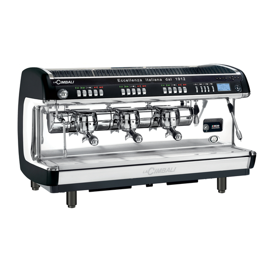
- Page 4 LEGEND Main Switch Selection panel Pump Pressure Gauge Hot water outlet Steam pipe Turbosteam pipe Filter-Holder Hot water button Turbosteam selector Tray Graphical display Ad display (*) Steam supply knob Electrical cup warmer button (*) Cups warmer (*) “RES” key (to quit programming mode / cancel entered data) Coffee circuit flushing key "i"...
- Page 5 tipo di macchina 2 gruppi 3 gruppi 4 gruppi type of machine 2 groups 3 groups 4 groups type de la machine 2 groupes 3 groupes 4 groupes Maschinentyp 2 Einheiten 3 Einheiten 4 Einheiten PED / DESP modelo de la máquina 2 grupos 3 grupos 4 grupos...
- Page 6 306 (12) 565 (22.2) 425 (16.7) DIMENSIONS 2 gr. 3 gr. 4 gr. 1055 1255 inches 33.7 41.5 49.4 ~ø100(3.9) inches 22.4 30.2 38.1 Weight pounds POWER INSTALLED LINE SUPPLY CABLE MACHINE SUPPLY POWER POWER SECTION 5x1,5 mm² or 5x2,5 mm² 380-415V3N 50/60Hz 4.2-5.0 kW 2 GR.
-
Page 7: Table Of Contents
Index Page Page PROGRAMMING - ENGINEER MODE Check - control messages Data flow chart - Technician programming Disassembly Access the programming menu Setting Electric heating Wiring diagram Key menu - Coffee selection Hydraulic circuit Key menu - Test Frame (Key “i”) Hydraulic Diagram Legend Key menu - Hot water selection Key menu - Select Steam and Air... -
Page 8: Data Flow Chart - Technician Programming
PROGRAMMING - ENGINEER MODE 1. Data flow chart - Technician programming To access menu press key + TECHNICAL PROG. 1.3 bar KEY MENU SELF.LEARNING CONFIGURATION TESTING To EXIT menu press key - key OK KEY MENU CONFIGURATION SELF.LEARNING TESTING Press Press Press SELECTION... -
Page 9: Electric Heating
2. Technical Programming Access 23 April 2014 Changing menus and sub-menus: position the cursor on the desired wednesday 15:15:04 line using the and keys and then press KEY MENU Type 1 coffee + Water dose 0100 Select grinder key and then OK for 3 seconds. To enter programming, press the The following message will appear on the display: Change the selection or value, again using the and keys TECHNICAL PROG. Note: when editing data, the cursor becomes “”, or a slider bar appears KEY MENU with the minimum and maximum values that can be set: + ... -
Page 10: Key Menu - Test Frame (Key "I")
4.1 KEY Menu - Test Frame (Key “i”) After entering the programming menu, access the key menu by pressing Pushing the “i” key (27), dispensing occurs and the relative settings are one of the drink-dispensing keys (the associate LED remains lit); the displayed on the screen: following will be shown on the display: - (E.g. Group 2 Key) MENU TASTO Type 1 coffee + Water dose 0100 Select grinder Key menu - Coffee selection T E S T M L / S ... - Page 11 Key menu - Turbosteam selection T E S T E t s L I V R C 1 5 ° Key menu - Grinding Control Selection T E S T M L / S L I V R C 1 5 °...
-
Page 12: Key Menu - Hot Water Selection
4.2 Key menu - Hot water selection Press key (12) hot water dispensing; the display will show: The hot water selection settings that can be changed are: - water dispensing time (water dispensing time from 0 to 60 seconds).. KEY MENU Type dosed + disp. time 20.0 4.3 Key Menu - Select Steam and Air Press one of the Turbosteam (13) selector keys (TS1 ÷ TS4). The following will appear on the display: TURBOSTEAM + T stop steam 072°C emulsion level 050 ... -
Page 13: Self. Learning Clone
Self. learning - Clone Press the key CLONE FUNCTION Place the cup or cups underneath the filter-holder nozzles and press the key to be programmed, holding until This function allows coffee dose settings of the right group to be the desired level is reached in the cup or cups. copied to all other groups. During this phase, the value of the impulses of the volumetric dosing device Once programming of the right group is complete, push OK. (top right on the display) is increased; when the key is released, At the end of the process, all the groups will have the same settings. the value reached is stored and appears on the display. TECHNICAL PROG. KEY MENU + Self. learning CONFIGURATION TESTING 6. - Page 14 6. Configuration menu Boiler - not active. Wi-Fi Menu - see section “Wi-Fi Configuration” in the pages that follow. MAINTENANCE - includes five items for setting maintenance parameters: Max cycles - the number of cycles initially set: 40000. Bluetooth Menu - see section “Bluetooth Connection” in the pages that follow Max days - the number of days initially set: 185. No. cycles - the number of cycles until the next maintenance activity. No. days- the number of days until the next maintenance activity. see section “BDS Activation” in the pages that follow. Reset - the choices are: NO, countdown of the cycles and days until the next maintenance activity YES, the number of cycles (40,000) and days (185) are reset OFF, all controls related to scheduled maintenance and the “No. cycles” and “No. days” on the maintenance panel are deactivated.
-
Page 15: Wifi Configuration
Service hours Washing Groups 1, 2, 3 - time: the time that washing must take place. These are the washes where the time can be programmed, each of The WASHES can be deactivated by setting to OFF. which contains two modifiable settings, including: - block coffee: when the function is set (YES), if washing has not been performed within 60 minutes of the “PERFORM GROUP WASH” message being displayed, the machine is blocked, disabling all coffee- WASH1 based selections. hour 15:30 + ... -
Page 16: Bluetooth Connection
Bluetooth Connection Bluetooth Card Bluetooth Menu - The parameters that can be set are: - MM1-MM2 - 1 to 2 grinders can be connected. - PassKey - on the configuration screen, enter the same code (7290) used for the grinder/dispenser and then press OK to confirm. - Search - the machine will find all bluetooth devices within 10 m. - Reset - cancels the connection with the associated device. Note: during connection with bluetooth grinders/dispensers, the first one connected is set as MM1. 10 EN... - Page 17 Procedure for Bluetooth connection with the machine-grinder unit Turn the machine on; the initial menu appears on the display. With the keys, place the cursor on: “CONFIGURATION” symbol indicates that the machine can be linked to a in the machine Technical Prog. menu and press the key: Bluetooth device. 23 April 2014 TECHNICAL PROG. wednesday 15:15:04 + KEY MENU SELF.LEARNING CONFIGURATION TESTING To enter TECHNICAL programming, press the key and then OK for 3 seconds. The message in Point 2 will appear on the display. Position the cursor on the “BLUETOOTH” entry and press the Position the cursor on the “Find” entry and press the key: key: CONFIGURATION ...
-
Page 18: Bds Activation
In the SW 047.00.H0 and subsequent versions, the connection is automatic and the symbol is displayed immediately. It is no longer necessary to press a dispensing key if the configuration has been completed successfully. In the event of communication problems, the “COMMUNICATION FAILURE” message will appear on the display followed by the name of the disconnected grinder/dispenser. The message disappears automatically when the Bluetooth connection is restored. A common cause of this failure is the grinder/dispenser being turned off with the machine turned on. -NOTE: Only for previous versions does the symbol remain on the display of the machine and the grinder/dispenser after setting wireless communication mode; when a double coffee dispensing key is pressed, the icons change to to indicate successful wireless communication. When the machine or grinder/dispenser are turned off, at the next power-on the symbol is shown on the display BDS activation and sensor configuration Return to the “CONFIGURATION” parameters by pressing the Use the keys to indicate... - Page 19 CONFIGURATION MAGNUM BLUETOOTH GRINDER/DISPENSER SENSORS 0: sensor disabled 1: single dose (Red) 2: double dose (Green) SINGLE DOSE (Red) B D S 1 - - 2 DOUBLE DOSE (Green) SPECIAL DOSE (White) B D S 1 - - 2 Single dose – Left sensor (Red) Double dose – Right sensor (Green) B D S 2 - - 1 B D S Double dose – Left sensor (Green) 0 - - 1...
- Page 20 Setting recipes and connections with grinder/dispenser -NOTE: POSSIBILITY TO CONNECT ALSO GRINDER/DISPENSER 1 WITH GRINDER/DISPENSER 2 KEY MENU type 1 coffee + Water dose 0100 Select grinder KEY MENU KEY MENU + type 1 coffee + coffee type 2 Water dose...
- Page 21 Operating logic BDS system enabled. Dispensing disabled (LED off) NOTE: Start/Stop key is always active. Dose grinding and dispensing activated (LED on) Dispensing will remain active for 2 minutes. During this time, the grinder/dispenser used will be blocked and therefore unable to grind a second dose of coffee. The grinder/dispenser will automatically release when the enabled key is pressed or when the two minutes of waiting time have elapsed. B L O C K E D 15 EN...
- Page 22 Configuration of grinding parameters Position the cursor on the “GRINDER CONTROL” entry in the machine The parameters that can be set are: configuration menu and press the key: Enabled - YES/NO. Set to “NO” during the machine configuration phase; “YES” once CONFIGURATION settings have been entered. Grinder control RELOAD COFFEE Grinder adjustment - YES/NO. USB log Before entering new flow rates (Q ref.), use the keys to Archive reset change the display to “YES” and then press OK to confirm. Note: after the operation, the setting returns to “NO”.
- Page 23 Dose time variation relative to the Magnum Bluetooth grinder/dispenser Note: single-measure’s and continuous measure grinding time variation in user mode is ± 25 hundredths of second To increase or decrease the measure-time operate as follows: (0 ÷ 1/4 second). 1) press the icon from the main screen: Double-measure’s grinding time variation in user mode is ±...
-
Page 24: Manual Control Panel
7. Manual control panel MANUAL CONTROLS - allows the components to be activated manually To access the manual control panels, position the cursor on the line using the and keys “Testing” using the keys When you press , the following message appears on the display: TECHNICAL PROG. TESTING + KEY MENU + MANUAL COMMANDS CONFIGURATION TESTING When the key is pressed again, the box below appears on the display: Panel 1 G R 1... - Page 25 Panel 2 G R 1 G R 2 G R 3 0 0 0 0 0 0 0 0 0 0 7 % R C 1 5 ° → → ± R E S Pressing or activates the components: if they have a direction, use or to alternate (“+” Left/”-” Right). Pressing takes you back to panel M1. Panel G R 1 G R 2 G R 3 0 0 0...
-
Page 26: Data Menu : Counters
Legend Below are the symbols used to define the components that can be accessed for movement: Pump Motor Boiler resistance Anti-backflow solenoid valve Boiler load solenoid valve Drying solenoid valve Boiler pressure Mc Autosteam compressor motor Boiler water level Ets Autosteam solenoid valve Steam temperature (if the Turbosteam system is not present, Evc Charge-boiler solenoid valve this parameter is not displayed) Cold-water solenoid valve Water solenoid valve G1÷G4... -
Page 27: Data Menu : Archive Rinsing
8.1 DATA menu: Wash 1 Archive For Wash 1, the settings that can be displayed are: DATA MENU - Requested: indicates the number of washes that were requested by + COUNTERS the machine. - Performed: indicates the number of washes that were performed WASH 1 ARCHIVE within the timeout of 60 minutes. Archive Rinsing MALFUNCT. ARCHIVE Averages Archive WASH 1 ARCHIVE Required 00005 Performed... -
Page 28: Data Menu : Malfunctions Archive
8.3 DATA menu: MALFUNCTIONS ARCHIVE The digits after the “malfunction code” indicate the time elapsed since the last recorded malfunction, in hours and minutes. DATA MENU COUNTERS + Pressing the key is again takes you to a detailed display that shows: WASH 1 ARCHIVE - day and time when the malfunction occurred Archive Rinsing - condition of each group at the time of the malfunction. MALFUNCT. ARCHIVE Averages Archive MALFUNCTION DETAIL Monday 23/04/14 098 11:22:25 When you press the key at the line “Malfunctions Archive”, the GR1: STANDBY display shows: GR2: STANDBY... -
Page 29: Data Menu : Info
DATA menu: INFO DATA MENU + INFO Serial number Pressing the key on the line “serial number”, the display shows. Positioning the cursor on the line “INFO” and pressing the keys, and then pressing the key, the following is displayed: SERIAL NUMBER INFO 123456 + SERIAL N° + VERSION SW SETUP DIP SETTINGS Version The submenus under “Version” show the memory versions: For some settings, pressing the key on the lines, data on the revision - Master 047.00.H0; and the date of the memory is also displayed in addition to the version. - Slave 050.00.H0; - Bluetooth;... -
Page 30: Entering Standard Data
Entering Standard Data Before performing this operation, turn off the machine and set CPU board During Standard Data entry, several parameters are to be set based on DIP switch 1 to ON, and then turn the machine on. the model and type of the machine: - TYPE: 2, 3, 4 groups; - TURBOSTEAM YES/NO; Using the keys choose the settings and then press the to confirm the entry. At the end of the operation, turn the machine off and reset CPU board DIP switch 1 to OFF. Then: - turn the machine on again - set the date and time and, if necessary, the desired language - reset the maintenance parameters, if desired (see “Configuration Menu - Maintenance”) -
Page 31: Check - Control Messages
NEWTON CHECK-CONTROL MESSAGES 25 EN... - Page 32 MALFUN. DESCRIPTION POSSIBLE CAUSES VERIFICATIONS and SOLUTIONS CODE (x)21* Group boiler pressure sensor x • Sensor failure • C heck cabling out of range (x = 1, 2, 3, 4) • Card failure • R eplace the sensor Note: Group 1 is to the far left. • R eplace the card Clock battery spent or missing • Oxidized contacts.
- Page 33 MALFUN. DESCRIPTION VERIFICATIONS and SOLUTIONS POSSIBLE CAUSES CODE Boiler-level signal errors. • Check the earthing and insulation of the machine. (x)66 E r r or in t he gr oup t ha t is • No water • C heck water is supplied from the main line. dispensing. • Flowmeter failure • C heck there are no fitting obstructions or leakage. (x = 1, 2, 3, 4) • Water circuit blocked • C heck flowmeter electrical connections.
-
Page 34: Disassembly
Smontaggio - Disassembly - Demontage - Abmontierung - Desmontaje - Desmontage Smontaggio - Disassembly - Demontage - Abmontierung - Desmontaje - Desmontage SCALDATAZZE: svitare le viti A e rimuovere le griglie. FIANCATE: svitare le viti B posizionate sotto le griglie, quindi rimuovere la fiancata. CUPWARMER: unscrew screws A and remove the grids. SIDE PANELS: unscrew screws B under the grids and then remove side panel. CHAUFFE-TASSES: dévisser les vis A et enlever les grilles. FLANCS: dévisser les vis B placées sous les grilles et puis enlever le flanc. - Page 35 Smontaggio - Disassembly - Demontage - Abmontierung - Desmontaje - Desmontage Smontaggio - Disassembly - Demontage - Abmontierung - Desmontaje - Desmontage PANNELLO FRONTALE INOX Togliere la bacinella appoggiatazze Svitare le due viti di fissaggio (D) e rimuovere il pannello frontale inox. STAINLESS STEEL FRONT PANEL Remove the cup tray Loosen the two fixing screws (D) and remove the stainless steel front panel.
-
Page 36: Setting
Regolazioni - Setting - Reglages - Einstellungen - Regulaciones - Regulações POMPA VOLUMETRICA CON FILTRO BY- PASS A - Dado di regolazione pressione pompa VOLUMETRIC PUMP WITH FILTER BY-PASS A - Nut for adjusting the pump pressure POMPE VOLUMETRIQUE AVEC FILTRE BY-PASS A - Ecrou de réglage pression pompe VOLUMETRISCHE PUMPE MIT FILTER BY-PASS A - Pumpendruck-Einstellschraube BOMBA VOLUMETRICA CON FILTRO BY-PASS A - Tuerca de regulación bomba BOMBA VOLUMETRICA COM FILTRO... - Page 37 Regolazioni - Setting - Reglages - Einstellungen - Regulaciones - Regulações SCATOLA ELETTRICA Togliere la bacinella appoggiatazze. Svitare la vite (C) e togliere il coperchio (D) della scatola elettrica facendolo scorrere verso l'interno macchina. JUNCTION BOX Remove the cup tray and the electric box protection below. Loosen the screw (C) and remove cover (D) from the junction box, making it to slide towards the machine. BOITE ÉLECTRIQUE Enlever le petit bassin appuie-tasses.
- Page 38 Regolazioni - Setting - Reglages - Einstellungen - Regulaciones - Regulações Chiudere il rubinetto di alimentazione idrica Close the water tap Fermer le robinet d’alimentation hydrique Sperren sie den hahn zur wasserversorgung ab Cerrar el grifo de alimentación hídrica Fechar a torneira de alimentação hídrica REGOLAZIONE DELLA TEMPERATURA DELL'ACQUA CALDA Per variare la temperatura, dell'acqua sostituire l'ugello (A) da...
-
Page 39: Wiring Diagram
Schema elettrico - Wiring diagram - Schéma éléctrique - Elektrischer Shaltplan - Esquema electrico - Esquema eléctrico... - Page 40 Schema elettrico - Wiring diagram - Schéma éléctrique - Elektrischer Shaltplan - Esquema electrico - Esquema eléctrico...
- Page 41 Schema elettrico - Wiring diagram - Schéma éléctrique - Elektrischer Shaltplan - Esquema electrico - Esquema eléctrico...
- Page 42 Schema elettrico - Wiring diagram - Schéma éléctrique - Elektrischer Shaltplan - Esquema electrico - Esquema eléctrico...
- Page 43 Schema elettrico - Wiring diagram - Schéma éléctrique - Elektrischer Shaltplan - Esquema electrico - Esquema eléctrico...
- Page 44 Schema elettrico - Wiring diagram - Schéma éléctrique - Elektrischer Shaltplan - Esquema electrico - Esquema eléctrico...
- Page 45 Schema elettrico - Wiring diagram - Schéma éléctrique - Elektrischer Shaltplan - Esquema electrico - Esquema eléctrico...
- Page 46 Schema elettrico - Wiring diagram - Schéma éléctrique - Elektrischer Shaltplan - Esquema electrico - Esquema eléctrico...
-
Page 47: Hydraulic Circuit
Circuito idraulico - Hydraulic circuit - Circuit hydraulique Hydraulikplan - Circuito hidraulico - Circuito hidráulico... - Page 48 Circuito idraulico - Hydraulic circuit - Circuit hydraulique Hydraulikplan - Circuito hidraulico - Circuito hidráulico...
-
Page 49: Hydraulic Diagram Legend
HYDRAULIC DIAGRAM LEGEND Ca = Boiler DV = Volumetric meter (flowmeter) Ea = Anti-suction solenoid valve Eac = Hot water solenoid valve Eaf = Cold water solenoid valve Ets = Turbosteam solenoid valve Evc = Service boiler water inlet solenoid valve Eds = EDS solenoid valve Fi = Pump filter = Coffee solenoid valve Gc = Coffee preparation group In = Injector MC = Compressore motor... - Page 50 Il Costruttore si riserva il diritto di modificare senza preavviso le caratteristiche delle apparecchiature presentate in questa pubblicazione The Manufacturer reserves the right to modify the appliances presented in this publication without notice Le fabricant se réserve le droit de modifier sans préavis les caractéristiques des appareils présentés dans cette publication Der Hersteller behält sich das Recht vor, die in dieser Veröffentlichung vorgestellten Geräte ohne Vorankündigung zu ändern...