Table of Contents
- 1 Table of Contents
- 2 Layout
- 3 Main Menus
- 4 Authorization Verification
- 5 System Configuration
- 6 Ground Speed Calibration
- 7 Hydraulic Valve Configuration
- 8 Material Calibration
- 9 Data Saving/Loading/Displaying
- 10 Sub Menus
- 11 Errors
- 12 Unload
- 13 Spreading Screen
- 14 Pause/Blast
- 15 Update Firmware
- 16 Logging Report
Table of Contents

Related Manuals for REXROTH CS 530


Summary of Contents for REXROTH CS 530
- Page 1 CS 530 Spreader Controller Configuration Manual...
-
Page 2: Table Of Contents
Please check for updates at www.boschrexroth.ca/compu-spread Rexroth reserves the right to revise this information at any time, without notice or obligation, to the information in this literature. Please check for updates at: www.boschrexroth.ca/cs... -
Page 3: Layout
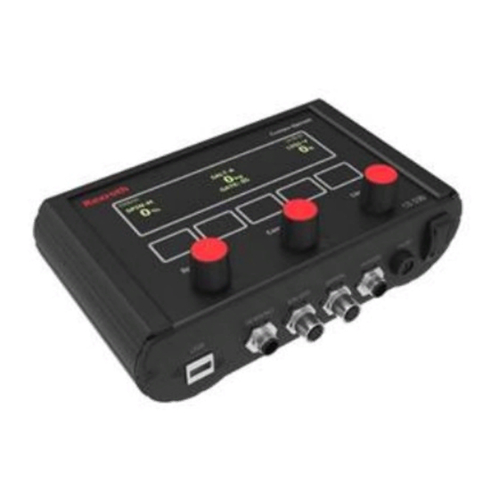
LAYOUT CS 530 is a three function programmable controller, available in Manual, Closed or Open Loop mode, for the controlled application of granular solids and liquids in snow and ice control. Three Encoders with push buttons Touch Pads Power Switch... -
Page 4: Authorization Verification
Key pads from left to right are for TOTAL, SETUP, MISC, SUBMENU and REVERSE. Pressing the touch panel pad enters the corresponding menu screen or holding REVS to reverse the conveyor. TOTAL ---- trip and season totals, data display / save / load / log SETUP ---- access to all settings of the system MISC ---- adjust the brightness of screen or driver ID if AVL attached... -
Page 5: System Configuration
SYSTEM CONFIGURATION If the password is correct or a program key is present, the setup screen below will be shown: * REGN: REGION BLST: 60X ALM: 88 UNIT: METRIC SPIN: S&P DI: N/A LOCK: P000000 MODE: STD DF: 150 TIME: 00:00:00 USER: M+G M/D/Y: 00-00-00 LIQU: PRE... - Page 6 Blast Timer and Mode BLST: The first two digits of ‘BLST’ is the blast timer in seconds & the last one digit is the mode of blasting. F --- Blast disabled C --- Blast at close loop with rate set at material screen. S --- 100% output even at zero ground speed X --- 100% output except at zero ground speed The default setting for blast timer is 60 seconds.
-
Page 7: Ground Speed Calibration
GROUND SPEED CALIBRATION There are two ways to input the ground speed calibration. If the resolution is known, just manually input the pulses per KM or Mile. The other way is to set a predetermined speed (speed the truck will be spreading at most often, is recommended). -
Page 8: Hydraulic Valve Configuration
HYDRAULIC VALVE CONFIGURATION The left side of screen is used to set up the valve configuration. * CONVEYOR 1 SALT MODE: AUTO BLAST: 0270 M99% SENSOR: 0050 RATE1: 0032 NULL: 15.0 75.0 WT/REV: 1.00 GAIN: 60% CAL GATE: 05 AUTONULL AUTOCAL PPAGE NPAGE... - Page 9 If the Closed loop mode is selected for Conveyor, V-Flow or Return Oil mode for Prewet, and 1Boom is selected for Anti-icing it is able to run Auto Null. --- Manual Mode-(M) This mode allows the driver to manually control the spread rate. Each setting on the Conveyor Dial 1–9 is a percentage of maximum valve null setting.
- Page 10 Null 1. Press ENTER to manually null the minimum and maximum current (in %) to the valve solenoids. WARNING: Once selected the conveyor or spinner has the ability to turn, and caution must be exercised. 2. Use up and down arrows to adjust the speed so that the motor just begins to turn. 3.
-
Page 11: Material Calibration
MATERIAL CONFIGURATION There are four solid material under the standard mode and two solid materials with air gate mode. Within the valves configuration page, the right side of the screen is for the corresponding material configuration. * CONVEYOR 1 SALT MODE: AUTO BLAST: 0270 M99% SENSOR: 0050... - Page 12 Note: This number will automatically be generated as a result of the weight / rev. calibration process (AUTOCAL) or you can input this value manually. CAL GATE Enter the correct gate setting at which the current solid material was calibrated at. AUTOCAL Here is where you can perform the material calibration if the controller is set to ‘Auto’...
-
Page 13: Data Saving/Loading/Displaying
DATA SAVING / LOADING / DISPLAYING Save parameters to the system All the changes made to the parameters will be updated and saved after pressing EXIT on the setup screen, the system will also give a text message screen as shown below. =============================== SAVE CONFIGURATION KEEP POWER ON! - Page 14 8.4 Loading parameters from USB key to Controller It is also possible to load saved parameters from a USB key to the controller on the screen. By pressing LPARA, the screen (as shown below) will list all the saved parameters files on the USB key. * REGION_TURC01 REGION_TURC06 REGION_TURC02...
-
Page 15: Sub Menus
SUB Menus SPEED SIMULATION When the truck is stopped (ground speed = 0), press to enter the screen as shown below. 0KMh 11:35:07 SPIN‒M SALT‒C LIQ1‒V GATE: 05 SMSPD SETUP Press SMSPD to enter speed simulation mode. 0KMh 11:35:07 SPIN‒M SALT‒C LIQ1‒V GATE: 05... - Page 16 Material change Depending on the setting of the USER options in the setup screen, GAT and MAT may show up on the sub menus. If, MAT is there, press MAT to enter the material adjustment screen. 0KMh 11:35:07 SPIN‒M SALT‒C LIQ1‒V GATE: 05 SMSPD...
-
Page 17: Errors
0KMh 11:35:07 SPIN‒M SALT‒C LIQ1‒V GATE: 05 HIGH ENTER Press ENTER again to exit. 10 ERRORS The controller continuously checks for errors during operation. E.g. the below screen shows that the ground speed is too high. (operator is driving faster than the programmed maximum speed setting) Warn: OVERSPEED Please Slow Down Truck An audible alarm and error message will display on screen for 4 seconds when an error occurs, then it will go off... -
Page 18: Unload
11 UNLOAD To unload remaining material after completion of the spreading operation, activate by pressing both the conveyor and the spinner dials simultaneously when spinner and conveyor rates are zero. (Note: The vehicle must be stationary.) WARNING: Once selected the conveyor or spinner has the ability to turn, and caution must be exercised. 0KMh 11:35:07 SPIN‒M... -
Page 19: Pause/Blast
14 UPDATE FIRMWARE Copy the latest .bin file to the root directory of a USB Program Key and rename it to Rexroth.bin. With the controller powered “off” insert the USB key into the USB port and then power “on” the controller, the controller will upgrade the firmware automatically. - Page 20 Data Zone 15.2 Select Report All the logging data will be displayed in the data zone. It is also possible to select the logging data involving multiple trucks under a single region. When selecting data, if the All Data option is selected and no specific truck is selected, then all the trucks in that region will be used.
- Page 21 15.3 View Report The logging reports will be displayed on the sheet called “Report” by clicking on ‘Display Truck’ after choosing the criteria from the above sections. For example, here you can select region “Toroto” and truck “TUCK03”. • Click Display Truck and it will go to the Report Sheet...
- Page 22 15.4 Delete Truck Truck data or region can be erased by clicking “Delete Truck”. A warning message will pop up to confirm the operation.