
Related Manuals for Samsung MCU-S6NEE1N


Summary of Contents for Samsung MCU-S6NEE1N
- Page 2 MCU-S6NEE1N MCU-S4NEE1N MCU-S4NEE2N MCU-S2NEK1N installation manual This manual is made with 100% recycled paper. imagine the possibilities Thank you for purchasing this Samsung product. EN ZH DB68-03490A-06...
-
Page 3: Table Of Contents
Contents Safety precautions ..........................................3 Preparing the installation ........................................5 Space requirements ..........................................7 Installing the unit ........................................... 8 Refrigerant piping works ......................................... 11 Wiring works ............................................13 Commisioning ............................................21... -
Page 4: Safety Precautions
Safety precautions The safety information and precautions below must be kept for the safety of users and installers. Before installing an air conditioner, please read this manual thoroughly to ensure that you know how to safely and efficiently install a new appliance. DVM S air conditioner uses R-410A refrigerant. - Page 5 Safety precautions FOR INSTALLATION WARNING Make sure to connect wires thoroughly and fix them firmly so that no outer pressure of the wires would put on the terminal block. If the terminal is loose, it may generate heat and cause a fire. Supplied power should be more or less than 2% of the rated power.
-
Page 6: Preparing The Installation
Preparing the installation Accessories Please check if items below are included in installation accessories. Insulation Insulation Installation Pattern Pipe Drain Name Cable tie (for base) (for pipe) manual sheet socket socket Shape Y-connector [Ø9.52mm(3/8") ,Ø15.88mm(5/8") Name (Except MCU-S2NEK1N)] Shape Selecting the refrigerant pipe for installation The design pressure of MCU for R-410A is about 4.1 MPa. - Page 7 Preparing the installation MCU indoor/outdoor unit compatible table Before installing MCU, refer to the compatible table below and find the model before installation. Outdoor Unit Indoor Unit MCU-S6NEE1N MCU-S4NEE1N AM✴✴✴✴X✴✴✴✴ AM✴✴✴✴N✴✴✴✴ MCU-S4NEE2N MCU-S2NEK1N Model Description Below 6 indoor units, below 56 kW (192MBH)
-
Page 8: Space Requirements
Space requirements 1. Since refrigerant noise can be generated during the MCU operation, do not install the unit on the ceiling of the places that requires silence such as bedrooms, libraries, hospitals and offices etc. 2. Do not install the MCU in the ceiling of the living area. Otherwise, noise generated from the MCU may disturb people in that area and cause inconvenience. -
Page 9: Installing The Unit
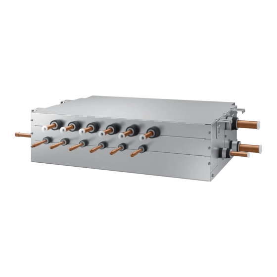
500mm(20") or more or more 700mm(28") or more Installing the unit 1. MCU specification MCU-S2NEK1N Model MCU-S6NEE1N MCU-S4NEE1N MCU-S4NEE2N Exterior of MCU Up to 2 units ❋ Refer to the detail Number of connectable Up to 6 units Up to 4 units... - Page 10 2. Installing the indoor unis MCU-S2NEK1N Model MCU-S6NEE1N MCU-S4NEE1N MCU-S4NEE2N Example installing The indoor unit's capacity of 20 14 kW(48 MHB) or under: kw(60 MBH) or over, must use the Single capacity range 10 kW(30 MBH) or under: Connect the liquid, gas pipe of...
- Page 11 Installing the unit 4. Cautions about MCU installation. When fixing the unit at the upper place using suspension bolts, use a nut and washer to vertically fasten the unit. There are four spots to fix the suspension bolts. Make sure every spot is fixed. The upper and the lower side of MCU is distinguished, so be careful not to turn the unit upside down when installing the unit.
-
Page 12: Refrigerant Piping Works
Refrigerant piping works Method and cautions on brazing the pipe Keeping refrigerant pipe clean and dry To prevent foreign materials or water from entering the pipe, it is important to keep the refrigerant pipe clean, dry and sealed during installation. Exposure place Exposure time Sealing type... - Page 13 Refrigerant piping works 5. Select the insulation of the refrigerant pipe. Insulate the gas side and liquid side pipe referring to the thickness according to the pipe size. Indoor temperature of 30°C(86°F) and humidity of 85% is the standard condition. If install in a high humidity condition, use one grade thicker insulator by referring to the table below.
-
Page 14: Wiring Works
Refrigerant piping works Draining form In a standard condition, drain installation is not required In a high humidity condition, drain installation is required High humidity condition: Indoor temperature of 30°C, relative humidity of 85% within MCU installation space Without the drain pump 1. - Page 15 Wiring works Earth cable Communication cable Indoor unit Power supply MCCB [A] ELB [A] Power cable (mm 1Ø, X [A], 0.0039 inch 220~240 V/50 Hz DVM Hydro X [A] 30 mA, (2.5 mm unit Max : 264 V 0.1 sec (Single Installation) Min : 198 V 1Ø, X [A], 0.0062 inch...
- Page 16 Installing the wire Supply the 220-240V/208-230V power to L1, L2 of MCU separately with outdoor unit. Connect the communication cable from the outdoor unit to F1, F2 of MCU. Power Line and communication line must be connected as shown in drawing. Case 1 Case 2 Indoor...
- Page 17 Wiring works Choose the compressed socket based on the cross-section of the connecting wire. Silver solder 1.5 (0.002) 2.5 (0.003) 4 (0.006) Nominal dimensions for cable [mm (inch2)] 4 (0.157) 4 (0.157) 4 (0.157) 4 (0.157) 4 (0.157) Nominal dimensions for screw [mm (inch)] 6.6 (0.259) 8 (0.314) 6.6 (0.259) 8.5 (0.334)
- Page 18 Setting MCU address Set the rotary switch of the indoor unit ADDRESS on the MCU PCB same as the ADDRESS of connected indoor unit. When installing more than 2 MCU, set each rotary switch for MCU ADDRESS properly. Outdoor Unit PCB Setting the number Setting the of Indoor Unit...
- Page 19 Wiring works Setting MCU option DIP switch for indoor unit setting (ON:Use, OFF:Not use) Rotary switch for Indoor unit ADDRESS Rotary switch for MCU ADDRESS Address on the rotary switch at the MCU PCB and the rotary switch on the indoor unit must be same. When installing more than 2 MCU’s set each rotary switch of MCU differently.
- Page 20 Key operation Display MCU status Display indoor unit's address EEV valve passive control Display segment Display Contents Remarks (Pushed time) Blank MCU address 0 Blank MCU address 1 MCU address Blank MCU address 2 Blank MCU address 11 Blank MCU address 15 Mode switching EEV1 step Ex) 480 steps Mode switching EEV2 step...
- Page 21 Wiring works K4 Switch (Electronic Valve Manual Control) According to the push time of K4 Switch, A_C, A_H, …, F_C, F_H, Liquid bypass solenoid valve opens in order. In Electronic Valve Manual Control mode, valve operates by K4 Push time irrespective of indoor operation mode. In Electronic Valve Manual Control mode, push K1 Switch makes DATA DISPLAY MODE to start and valves will operate following indoor operation mode.
-
Page 22: Commisioning
Commisioning ❈ After installing MCU, check those items below. If you find something unfulfilled, refer to the manual to complete it. Item Check 1. If the gas leaking test has been completed or not. 2. If MCU has been fixed securely enough to avoid the danger of vibration and falling or not. 3. - Page 23 Memo...
- Page 24 Memo...