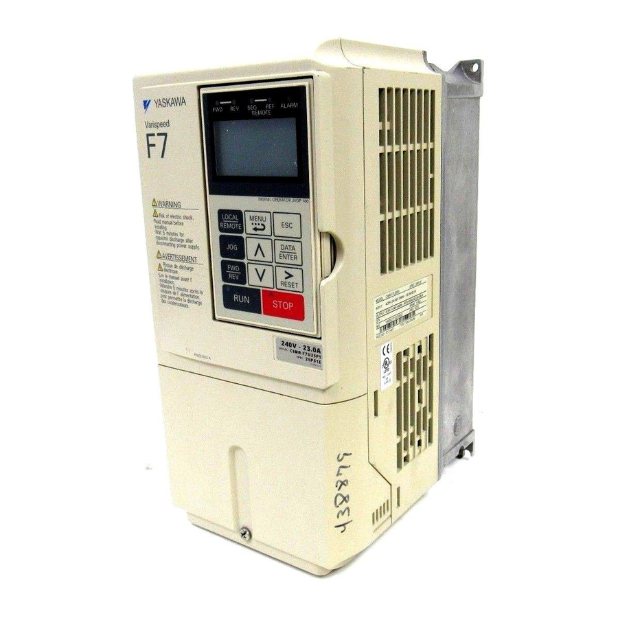
YASKAWA F7 Technical Manual
Enhanced pid for air compressors f7 drive software
Hide thumbs
Also See for F7:
- Instruction manual (463 pages) ,
- User manual (256 pages) ,
- Programming manual (202 pages)
Quick Links
See also:
Instruction Manual, User Manual
Software Number: VSF11020X, Drive Models: CIMR-F7UXXXXXX-096
Document Number: TM.F7SW.096, Date: 08/01/05, Rev: 05-08
Enhanced PID for
Air Compressors
F7 Drive Software
Technical Manual

Related Manuals for YASKAWA F7


Summary of Contents for YASKAWA F7
- Page 1 Enhanced PID for Air Compressors F7 Drive Software Technical Manual Software Number: VSF11020X, Drive Models: CIMR-F7UXXXXXX-096 Document Number: TM.F7SW.096, Date: 08/01/05, Rev: 05-08...
- Page 2 This document is intended to provide proper installation and use of the Yaskawa drive with custom software. This document is a supplement to the standard drive technical manual. It describes the effects on the drive parameters and functions with the software installed. Read and understand this document and the standard drive technical manuals before attempting to install, adjust, operate, inspect or maintain the drive.
- Page 3 1.1 Simplified Block Diagram of Enhanced PID: 2 Input (B5-01 = 1 or 2) 1.2 Simplified Block Diagram of Enhanced PID: 3 Input (B5-01 = 3 or 4) (PID setpoint is independent of frequency reference) 1.3 Simplified Block Diagram of Enhanced PID: 2 Input (B5-01 = 3 or 4) (PID setpoint is same as the frequency reference) Date: 08/01/05, Rev: 05-08 Page 3 of 17...
- Page 4 2.0 Changes from Standard Product 2.1 Enhanced PID versus Standard Software Enhanced Standard Feature Software √ √ Full Range PID (2-input) √ √ PID + Frequency Reference Capable (3-input) √ PID x Frequency Reference Capable (3-input) √ PID Setpoint Offset Parameter PID + Trim is Accomplished Algebraically, Regardless of Commanded √...
- Page 5 4. Related Parameters and Functions 4.1 Parameters Parameter Name Description Digital Operator Display Frequency Selects the frequency reference source. Reference 0: Operator Selection 1: Control Terminal Strip B1-01 180H 0 ~ 4 2: Modbus RTU (Terminals R+, R-, S+, S-) 3: Option Card Reference 4: Pulse Input (Terminal RP)
- Page 6 4.1 Parameters (continued) Parameter Name Description Digital Operator Display Feedback Detection -100.0 This parameter sets the detection level Level (High) P1-02 601H for PID feedback (high) detection 100.0 +100.0 function. Fb Det Lvl High Feedback On- This parameter sets the on-delay time for Delay Time (High) P1-03 602H...
- Page 7 4.1 Parameters (continued) Parameter Name Description Digital Operator Display This parameter sets the gain at the output of the PID. Functions the same PID Output Gain 2 0.00 as PID Output Gain (B5-10), but with P2-02 60BH 1.00 finer resolution (0.01 versus 0.1). The 25.00 Output Gain 2 total output gain is determined by B5-...
- Page 8 4.1 Parameters (continued) Parameter Name Description Digital Operator Display This parameter determines what custom units are displayed for U1-01, D1-XX, and U1-90 thru U1-96. Custom Units 0: No units displayed Display Selection P2-09 612H 1: PSI 0 ~ 3 2: kPa Custom Units Note: Only applicable when O1-03 ≥...
- Page 9 4.2 Monitors (U1-XX) Control Mode *1 Scaling for Multi- Monitor Name function Analog Outputs Description Unit Digital Terminals Operator FM and AM Display (H4-01, H4-04) Frequency 100%: Reference Displays the 0.01 Maximum Output U1-01 040H frequency Frequency reference. Frequency (E1-04) Output 100%: Displays the output...
- Page 10 4.2 Monitors (U1-XX) (continued) Control Mode *1 Scaling for Multi- Monitor Name function Analog Outputs Description Unit Digital Terminals Operator FM and AM Display (H4-01, H4-04) Displays the PID PID Integral 100%: integral value as a Output Maximum Output 0.1% U1-94 724H percentage of...
- Page 11 4.5 Modbus Registers Modbus Monitor Description Unit Address Name 024H Output Frequency Output frequency monitor 0.01Hz *4 *4: Scaling based on P2-10 (Output Monitor Units) setting. Parameter P2-10 programs and functions exactly like standard parameter O1-03. 4.6 Faults Fault Display Description Cause Countermeasures...
- Page 12 5.2 Modified PID “Sleep” Function In standard software, parameter B5-16 controls both the sleep delay, and the wake-up delay. In this software, parameter B5-16 controls the sleep delay, and P2-06 controls the wake-up delay. maximum settable range of B5-16 is increased from 25.5 seconds to 600.0 seconds. An additional timer has been added (P2-07) to the sleep function to insure that when the drive does go into the sleep mode, it remains in sleep mode even if the PID is calling for the drive to run.
- Page 13 6.1 Enhanced PID with 2 Inputs (B5-01 = 1 or 2) Date: 08/01/05, Rev: 05-08 Page 13 of 17 TM.F7SW.096...
- Page 14 6.2 Enhanced PID with 2 Inputs (B5-01 = 3 or 4) Date: 08/01/05, Rev: 05-08 Page 14 of 17 TM.F7SW.096...
- Page 15 6.3 Enhanced PID with 3 Inputs (B5-01 = 3 or 4) Date: 08/01/05, Rev: 05-08 Page 15 of 17 TM.F7SW.096...
- Page 16 6.4 Enhanced PID Feedback Detection Date: 08/01/05, Rev: 05-08 Page 16 of 17 TM.F7SW.096...
- Page 17 6.5 PID Sleep Function and Blowdown Valve Digital Output Date: 08/01/05, Rev: 05-08 Page 17 of 17 TM.F7SW.096...