Siemens SITRANS P DS III Operating Instructions Manual
Pressure transmitter with hart
Hide thumbs
Also See for SITRANS P DS III:
- Manual (282 pages) ,
- Operating instructions manual (266 pages) ,
- Service manual (74 pages)
Table of Contents
Quick Links
Table of Contents

Related Manuals for Siemens SITRANS P DS III


Summary of Contents for Siemens SITRANS P DS III
- Page 3 ___________________ SITRANS P DS III with HART Introduction ___________________ Safety instructions ___________________ Description SITRANS ___________________ Installing/mounting Pressure transmitter ___________________ SITRANS P DS III with HART Connecting ___________________ Operation Operating Instructions ___________________ Operating functions through HART ___________________ Functional safety ___________________ Commissioning...
- Page 4 Note the following: WARNING Siemens products may only be used for the applications described in the catalog and in the relevant technical documentation. If products and components from other manufacturers are used, these must be recommended or approved by Siemens. Proper transport, storage, installation, assembly, commissioning, operation and maintenance are required to ensure that the products operate safely and without any problems.
-
Page 5: Table Of Contents
Measuring cell for absolute pressure, front-flush membrane ............32 Remote seal ..........................33 SIMATIC PDM ..........................34 Installing/mounting ..........................35 Basic safety instructions ......................35 4.1.1 Installation location requirements ....................39 4.1.2 Proper mounting........................... 39 SITRANS P DS III with HART Operating Instructions, 06/2013, A5E00047092-09... - Page 6 6.5.5.3 Blind setting of full scale value ....................90 6.5.5.4 Blind adjusting of the start of scale value ..................90 6.5.5.5 Blind adjustment of the full scale value ..................91 SITRANS P DS III with HART Operating Instructions, 06/2013, A5E00047092-09...
- Page 7 Trimming the sensor ........................130 7.17 Current sensor trim ........................130 7.18 Factory calibration ........................132 7.19 Static configuration data ......................132 7.20 Flow rate measurement (only differential pressure) ..............134 SITRANS P DS III with HART Operating Instructions, 06/2013, A5E00047092-09...
- Page 8 Display in case of a fault ......................170 10.2.4 Changing the measuring cell and application electronics ............170 10.3 Cleaning ............................ 171 10.3.1 Servicing the remote seal measuring system ................172 10.4 Return procedure ........................173 SITRANS P DS III with HART Operating Instructions, 06/2013, A5E00047092-09...
- Page 9 SITRANS P, DS III for gauge pressure and absolute pressure from the gauge pressure series ............................203 12.2 SITRANS P DS III for differential pressure, flow rate and absolute pressure from the differential pressure series ......................205 12.3 SITRANS P DS III for level ......................208 12.4...
- Page 10 Table of contents SITRANS P DS III with HART Operating Instructions, 06/2013, A5E00047092-09...
-
Page 11: Introduction
The programming manual is an integral part of the CD, which is either supplied or can be ordered. The programming manual is also available on the Siemens homepage. On the CD, you will also find the catalog extract with the ordering data, the Software Device Install for SIMATIC PDM for additional installation, and the required software. -
Page 12: History
Absolute pressure from the differential pressure series 7MF4433 Differential pressure and flow rate, PN 32/160 (MAWP 464/2320 psi) 7MF4533 Differential pressure and flow rate, PN 420 (MAWP 6092 psi) 7MF4633 Level SITRANS P DS III with HART Operating Instructions, 06/2013, A5E00047092-09... -
Page 13: Checking The Consignment
● Devices/replacement parts should be returned in their original packaging. ● If the original packaging is no longer available, ensure that all shipments are properly packaged to provide sufficient protection during transport. Siemens cannot assume liability for any costs associated with transportation damages. -
Page 14: Notes On Warranty
The sales contract contains all obligations on the part of Siemens as well as the complete and solely applicable warranty conditions. Any statements regarding device versions described in the manual do not create new warranties or modify the existing warranty. -
Page 15: Safety Instructions
● National Electrical Code (NEC - NFPA 70) (USA) ● Canadian Electrical Code (CEC) (Canada) Further provisions for hazardous area applications are for example: ● IEC 60079-14 (international) ● EN 60079-14 (EC) SITRANS P DS III with HART Operating Instructions, 06/2013, A5E00047092-09... -
Page 16: Conformity With European Directives
Due to the large number of possible applications, each detail of the described device versions for each possible scenario during commissioning, operation, maintenance or operation in systems cannot be considered in the instructions. If you need additional information not covered by these instructions, contact your local Siemens office or company representative. Note... -
Page 17: Use In Hazardous Areas
• Connect the device with type of protection "Intrinsic safety" solely to an intrinsically safe circuit. • Observe the specifications for the electrical data on the certificate and in Chapter "Technical data (Page 175)". SITRANS P DS III with HART Operating Instructions, 06/2013, A5E00047092-09... - Page 18 • Devices and tools used must be free of static charge. • Hold modules only by their edges. • Do not touch connector pins or conductor tracks on a module with the ESD notice. SITRANS P DS III with HART Operating Instructions, 06/2013, A5E00047092-09...
-
Page 19: Description
● PC with HART modem, on which appropriate software is installed, e.g. SIMATIC PDM (load 230 ... 500 Ω) ● Control system which can communicate via the HART protocol, e.g. SIMATIC PCS7 Figure 3-1 Possible system configurations SITRANS P DS III with HART Operating Instructions, 06/2013, A5E00047092-09... -
Page 20: Application Range
● Gauge pressure, suitable for small positive or negative pressure value ● in combination with a restrictor device: flow rate q ~ The smallest measuring span is 1 mbar (0.0145 psi), the largest 30 bar (435 psi). SITRANS P DS III with HART Operating Instructions, 06/2013, A5E00047092-09... - Page 21 100 bar a (1450 psi a). The smallest measuring span of the "gauge pressure" series is 8.3 mbar a (0.12 psi a), and the largest is 30 bar a (435 psi a). SITRANS P DS III with HART Operating Instructions, 06/2013, A5E00047092-09...
-
Page 22: Structure
● The protective conductor terminal/equipotential bonding terminal is located at the back of the enclosure. ⑩ ● The electrical terminal compartment for the auxiliary power and shield is accessible ⑨ when you remove the back cover SITRANS P DS III with HART Operating Instructions, 06/2013, A5E00047092-09... -
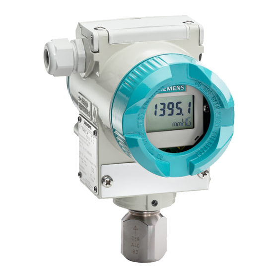
Page 23: Nameplate Layout
The nameplate bearing the Order No. and other important information, such as design details and technical data, is on the side of the enclosure. ① ② Order number (machine-readable product Serial number code) Figure 3-3 Example of a nameplate SITRANS P DS III with HART Operating Instructions, 06/2013, A5E00047092-09... -
Page 24: Measuring Point Label Layout
Example of a nameplate Measuring point label layout Figure 3-5 Example of measuring point label Functional principle 3.6.1 Overview of mode of operation This chapter describes how the transmitter works. SITRANS P DS III with HART Operating Instructions, 06/2013, A5E00047092-09... -
Page 25: Operation Of The Electronics
● This signal is amplified by the measuring amplifier and digitized in an analog-to-digital ③ converter ④ ● The digital signal is analyzed in a microcontroller and corrected with regard to linearity and thermal characteristics. SITRANS P DS III with HART Operating Instructions, 06/2013, A5E00047092-09... -
Page 26: Measuring Cell Operation
In the following sections, the process variable to be measured is called general inlet pressure. Overview The following modes of operation are described: ● Gauge pressure ● Absolute pressure ● Differential pressure and flow rate ● Level SITRANS P DS III with HART Operating Instructions, 06/2013, A5E00047092-09... -
Page 27: Measuring Cell For Gauge Pressure
Transmitters with measuring span ≤ 63 bar measure the inlet pressure against atmosphere, those with measuring spans ≥ 160 bar against vacuum. SITRANS P DS III with HART Operating Instructions, 06/2013, A5E00047092-09... -
Page 28: Measuring Cell For Differential Pressure And Flow Rate
(bridge circuit) of the differential pressure sensor. ● The change in the resistance causes a bridge output voltage proportional to the differential pressure. SITRANS P DS III with HART Operating Instructions, 06/2013, A5E00047092-09... -
Page 29: Measuring Cell For Level
The displacement changes the resistance of the four doped piezoresistors in the bridge circuit. ● The change in the resistance causes a bridge output voltage proportional to the differential pressure. SITRANS P DS III with HART Operating Instructions, 06/2013, A5E00047092-09... -
Page 30: Measuring Cell For Absolute Pressure From The Differential Pressure Series
(bridge circuit) of the absolute pressure sensor. ● The change in the resistance causes a bridge output voltage proportional to the absolute pressure. SITRANS P DS III with HART Operating Instructions, 06/2013, A5E00047092-09... -
Page 31: Measuring Cell For Absolute Pressure From The Gauge Pressure Series
, displacing its measuring diaphragm. The displacement changes the resistance of the four piezoresistors (bridge circuit) of the absolute pressure sensor. The change in the resistance causes a bridge output voltage proportional to the inlet pressure. SITRANS P DS III with HART Operating Instructions, 06/2013, A5E00047092-09... -
Page 32: Measuring Cell For Gauge Pressure, Front-Flush Membrane
Measuring cell Filling liquid ② ⑤ Process connection Absolute pressure sensor ③ Seal diaphragm Inlet pressure Figure 3-13 Function chart of the measuring cell for absolute pressure, flush mounted diaphragm SITRANS P DS III with HART Operating Instructions, 06/2013, A5E00047092-09... -
Page 33: Remote Seal
● The loss of transmission fluid results in inaccuracies in the measurement and failure of the measuring system. ● In order to avoid leaks and measuring errors, please observe the installation and maintenance instructions in addition to the safety notes. SITRANS P DS III with HART Operating Instructions, 06/2013, A5E00047092-09... -
Page 34: Simatic Pdm
SIMATIC PDM allows the process device data to be: ● displayed ● set ● modified ● saved ● diagnosed ● checked for plausibility ● managed ● simulated SITRANS P DS III with HART Operating Instructions, 06/2013, A5E00047092-09... -
Page 35: Installing/Mounting
Note Material compatibility Siemens can provide you with support concerning selection of sensor components wetted by process media. However, you are responsible for the selection of components. Siemens accepts no liability for faults or failures resulting from incompatible materials. - Page 36 • In the case of a conduit system, mount a spark barrier at a defined distance from the device input. Observe national regulations and the requirements stated in the relevant approvals. See also Technical data (Page 175) SITRANS P DS III with HART Operating Instructions, 06/2013, A5E00047092-09...
- Page 37 Loss of explosion protection Danger of explosion in hazardous areas if the device is open or not properly closed. • Close the device as described in Chapter "Connecting the device (Page 62)". SITRANS P DS III with HART Operating Instructions, 06/2013, A5E00047092-09...
- Page 38 Damage to device by severe external stresses and loads (e.g. thermal expansion or pipe tension). Process media can be released. • Prevent severe external stresses and loads from acting on the device. SITRANS P DS III with HART Operating Instructions, 06/2013, A5E00047092-09...
-
Page 39: Installation Location Requirements
• Make sure that process connectors are clean, and suitable gaskets and glands are used. • Mount the device using suitable tools. Refer to the information in Chapter "Technical data (Page 175)", for example installation torques requirements. SITRANS P DS III with HART Operating Instructions, 06/2013, A5E00047092-09... -
Page 40: Disassembly
• If the device contains dangerous media, it must be emptied prior to disassembly. Make sure that no environmentally hazardous media are released. • Secure the remaining connections so that no damage can result if the process is started unintentionally. SITRANS P DS III with HART Operating Instructions, 06/2013, A5E00047092-09... -
Page 41: Installation (Except Level)
Install the transmitter below the pressure tapping point. Lay the pressure tubing with a constant gradient to the pressure tapping point so that any gas pockets can escape in the main line. SITRANS P DS III with HART Operating Instructions, 06/2013, A5E00047092-09... -
Page 42: Installation (Except Level)
● On a wall or a mounting frame using two screws ● On a vertical or horizontal mounting tube (Ø 50 to 60 mm) using a tube bracket Fasten the transmitter mounting bracket using the two screws provided. SITRANS P DS III with HART Operating Instructions, 06/2013, A5E00047092-09... - Page 43 Fastening the transmitter on the mounting bracket Figure 4-2 An example of fastening the transmitter on the mounting bracket in the case of differential pressure and horizontal differential pressure lines SITRANS P DS III with HART Operating Instructions, 06/2013, A5E00047092-09...
-
Page 44: Level" Installation
Instructions for level installation Requirements Note Compare the desired operating data with the data on the nameplate. Please also refer to the information on the remote seal if this is fitted. SITRANS P DS III with HART Operating Instructions, 06/2013, A5E00047092-09... -
Page 45: Installation For Level
Ensure that the seal is centrically positioned and that it does not restrict the movement of the flange's seal diaphragm in any way as otherwise the tightness of the process connection is not guaranteed. 2. Screw on the transmitter's flange. 3. Observe the installation position. SITRANS P DS III with HART Operating Instructions, 06/2013, A5E00047092-09... -
Page 46: Connection Of The Negative Pressure Line
Measurement assembly on an open container Lower filling level Δp Start of scale value Upper filling level Δp Full-scale value Pressure ρ Density of the measured medium in the container Acceleration due to gravity SITRANS P DS III with HART Operating Instructions, 06/2013, A5E00047092-09... - Page 47 (mostly with the condensate of the measured medium) and install a condensate pot. You can cut off the device using the dual pneumatic block 7MF9001-2. SITRANS P DS III with HART Operating Instructions, 06/2013, A5E00047092-09...
- Page 48 The process connection on the negative side is a female thread -18 NPT or an oval flange. Lay the line for the negative pressure using a seamless steel tube 12 mm x 1.5 mm. SITRANS P DS III with HART Operating Instructions, 06/2013, A5E00047092-09...
-
Page 49: Remote Seal" Installation
The pressure rating specified on the remote seal applies to reference conditions according to IEC 60770. • For the maximum permissible pressure at higher temperatures, please refer to the standard specified on the remote seal. SITRANS P DS III with HART Operating Instructions, 06/2013, A5E00047092-09... -
Page 50: Installation Of The Remote Seal With The Capillary Line
– If halocarbon oil is used as the filling liquid, this maximum height difference is only = 4 m, see installation types A and B. 1max. If negative overpressure is observed during measurements, reduce the permissible height difference accordingly. SITRANS P DS III with HART Operating Instructions, 06/2013, A5E00047092-09... - Page 51 Distance between the container flange and the pressure transmitter For absolute pressure measurements (vacuum), install the measuring device at least at the height of the remote seal or below it (see installation types C). SITRANS P DS III with HART Operating Instructions, 06/2013, A5E00047092-09...
- Page 52 Full scale pressure ρ Density of the filling oil in the capillary line of the remote seal Acceleration due to gravity Distance between the container flange and the pressure transmitter SITRANS P DS III with HART Operating Instructions, 06/2013, A5E00047092-09...
- Page 53 Full-scale value Start of scale pressure start Full scale pressure ρ Density of the filling oil in the capillary line of the remote seal Acceleration due to gravity Gland distance SITRANS P DS III with HART Operating Instructions, 06/2013, A5E00047092-09...
- Page 54 Density of the process medium in the container ρ Density of the filling oil in the capillary line of the remote seal Acceleration due to gravity Lower filling level Upper filling level Gland distance SITRANS P DS III with HART Operating Instructions, 06/2013, A5E00047092-09...
- Page 55 = ρ * g * H - ρ * g * H Full-scale value: = ρ * g * H - ρ * g * H Below the lower measuring point SITRANS P DS III with HART Operating Instructions, 06/2013, A5E00047092-09...
-
Page 56: Turing The Measuring Cell Against Housing
③ electronic housing. An orientation mark is provided at the throat of the measuring cell. This mark must remain in the marked section when turning. SITRANS P DS III with HART Operating Instructions, 06/2013, A5E00047092-09... - Page 57 (Allen screw 2.5 mm). 2. Turn the electronic housing against the measuring cell. Follow the marked turning range ① while doing so. 3. Tighten the retaining screw (torque: 3.4 to 3.6 Nm). SITRANS P DS III with HART Operating Instructions, 06/2013, A5E00047092-09...
-
Page 58: Rotating The Display
You can turn it by ±90° or ±180°. 3. Screw the covers back on as far as they will go. 4. Secure the covers with the cover catch. SITRANS P DS III with HART Operating Instructions, 06/2013, A5E00047092-09... -
Page 59: Connecting
• Connect the device in accordance with the specified power supply and signal circuits. The relevant specifications can be found in the certificates, in Chapter "Technical data (Page 175)" or on the nameplate. SITRANS P DS III with HART Operating Instructions, 06/2013, A5E00047092-09... - Page 60 • Circuits of limited energy may also be connected in the energized state in hazardous areas. • Exceptions for type of protection "Non-sparking nA" (Zone 2) are regulated in the relevant certificate SITRANS P DS III with HART Operating Instructions, 06/2013, A5E00047092-09...
- Page 61 For metal housings there is an increased electromagnetic compatibility compared to high- frequency radiation. This protection can be increased by grounding the housing, see Chapter "Connecting the device (Page 62)". SITRANS P DS III with HART Operating Instructions, 06/2013, A5E00047092-09...
-
Page 62: Connecting The Device
• Refer to HART communication information in Chapter "Technical data (Page 175)". Connecting the device Opening the device 1. Unscrew the cover of the electrical cable compartment. An identification text "FIELD TERMINAL" is provided at the side of the housing. SITRANS P DS III with HART Operating Instructions, 06/2013, A5E00047092-09... - Page 63 Safety catch ③ ⑦ Cable entry for auxiliary power/analog Protective conductor connection/ output equipotential bonding terminal ④ ⑧ Connecting terminals Process connection ⑨ Ground terminal Figure 5-1 Electrical connection, power supply SITRANS P DS III with HART Operating Instructions, 06/2013, A5E00047092-09...
-
Page 64: Connecting The Han Plug
Structure (Page 22) Connecting the Han plug WARNING The connector may only be used for Ex ia devices and non-Ex devices; otherwise the safety required for the approval is not guaranteed. SITRANS P DS III with HART Operating Instructions, 06/2013, A5E00047092-09... - Page 65 3. Crimp the contact parts on the cable ends. 4. Assemble the coupling socket. Output current Auxiliary power Connector pin assignment with Han 7D or Han 8D plug See also Technical data (Page 175) SITRANS P DS III with HART Operating Instructions, 06/2013, A5E00047092-09...
-
Page 66: Connecting The M12 Connector
Figure 5-3 Preparing the connecting cable ① ③ Reference edge for stripping Insulating sleeve over the shield ② ④ Reference edge for the dimension Shrink sleeve specifications for cable assembly SITRANS P DS III with HART Operating Instructions, 06/2013, A5E00047092-09... - Page 67 Layout for M12 jack ① ① M12 x 1 thread Positioning slot ② Positioning catch Not connected Not connected Shield Shield Middle jack contact not connected See also Technical data (Page 175) SITRANS P DS III with HART Operating Instructions, 06/2013, A5E00047092-09...
- Page 68 Connecting 5.4 Connecting the M12 connector SITRANS P DS III with HART Operating Instructions, 06/2013, A5E00047092-09...
-
Page 69: Operation
Blind adjustment of the full scale value Zero point calibration (position correction) Current transmitter Fault current Keyboard lock and write protection Yes, release except for write protection Unit type, unit SITRANS P DS III with HART Operating Instructions, 06/2013, A5E00047092-09... -
Page 70: Basic Safety Instructions
The operating instructions in the "Local operation without display" section apply if the device has been delivered with a blind cover. SITRANS P DS III with HART Operating Instructions, 06/2013, A5E00047092-09... -
Page 71: Display
Violation of upper limit displays are also referred to as status since they have meanings dependent on the settings. ⑧ If the communication display blinks, this indicates an active communication. SITRANS P DS III with HART Operating Instructions, 06/2013, A5E00047092-09... -
Page 72: Units Display
The status of one of the device variables is • "UNCERTAIN". "SIMULATION" Is always displayed when the simulation of a pressure value or temperature value is active. See also Measured value status (Page 116) SITRANS P DS III with HART Operating Instructions, 06/2013, A5E00047092-09... -
Page 73: Error Display
Event counter for limit values exceeded – Calibration time expired – Current saturation reached the status of one of the device variables is "BAD". • "SENSOR BREAK" Appears when there is a sensor break. SITRANS P DS III with HART Operating Instructions, 06/2013, A5E00047092-09... -
Page 74: Mode Display
Adjusting damping if the upper damping value is if the value falls below the exceeded lower damping value only for the pressure device version only for the pressure device version SITRANS P DS III with HART Operating Instructions, 06/2013, A5E00047092-09... -
Page 75: Overflow Range
Violations of the measured value limits are output on the display by or . Note The setting of the overflow range and the fault current range can be freely selected via HART communication. SITRANS P DS III with HART Operating Instructions, 06/2013, A5E00047092-09... -
Page 76: Local Operation
Display Increment key ② ⑤ Connecting plug for the display Decrement key ③ ⑥ Mode key Key symbols shown in the key cover Figure 6-5 Position of keys and display SITRANS P DS III with HART Operating Instructions, 06/2013, A5E00047092-09... - Page 77 Measured value in pressure unit Current Current Current switch on constant output current in mA transmitter higher lower "3.6"; "4", "12", "20" or "22.8" Switch off using the [M] key. SITRANS P DS III with HART Operating Instructions, 06/2013, A5E00047092-09...
- Page 78 Y22, unit as from the specified) table of the physical unit Not relevant for gauge and absolute pressure) See also Overview of operation (Page 69) Operating functions through HART communication (Page 105) SITRANS P DS III with HART Operating Instructions, 06/2013, A5E00047092-09...
-
Page 79: Operation Using Buttons
Modes 2 and 3 are used for this. Rising and falling characteristic curves can be realized with appropriate use of the buttons. If the transmitter is not in "Pressure" measuring mode, this mode is skipped in local operation. SITRANS P DS III with HART Operating Instructions, 06/2013, A5E00047092-09... - Page 80 Current calculation formula for setting Example of setting with reference pressure A Initial situation B Setting start of scale value C Setting full scale value Explanations for the example of setting with reference pressure SITRANS P DS III with HART Operating Instructions, 06/2013, A5E00047092-09...
- Page 81 To calculate the output currents when setting the start of scale value or the full scale value, the reference pressure must be selected such that a value between 4 and 20 mA results for the current. SITRANS P DS III with HART Operating Instructions, 06/2013, A5E00047092-09...
- Page 82 The "Current calculation formula for adjusting" can be used to calculate the current to be adjusted for the desired full scale value I (16 mA at 14 bar) with the existing reference pressure. It can be adjusted with the [↑] or [↓] buttons I SITRANS P DS III with HART Operating Instructions, 06/2013, A5E00047092-09...
-
Page 83: Setting/Adjusting The Start Of Scale Value
To set the output current of the start of scale value to 4 mA, proceed as follows: 1. Create the reference pressure. 2. Set mode 2. 3. Set the start of scale value to 4 mA. 4. Save with the [M] button. SITRANS P DS III with HART Operating Instructions, 06/2013, A5E00047092-09... -
Page 84: Setting/Adjusting The Full Scale Value
Set or adjust the full scale value of the pressure transmitter in mode 3. You can also adjust the start of scale value or the full scale value separately as well as adjust both these values one after the other. SITRANS P DS III with HART Operating Instructions, 06/2013, A5E00047092-09... - Page 85 You have a device with a cover that does not have an inspection window and you do not wish to set the full scale value, but adjust it continuously. You will need an ammeter for this purpose. SITRANS P DS III with HART Operating Instructions, 06/2013, A5E00047092-09...
-
Page 86: Setting/Adjusting Electrical Damping
Condition for "adjusting" The default setting of steps is an interval of 0.1 seconds. If you press the [↑] or [↓] button for a longer time, the step is increased. SITRANS P DS III with HART Operating Instructions, 06/2013, A5E00047092-09... -
Page 87: Blind Start Of Scale Value/Full Scale Value
(measuring span ratio = r, turn down). The correlation between the measured pressure and the output current generated is linear. The square root extracting characteristic curve for differential pressure transmitters is an exception. SITRANS P DS III with HART Operating Instructions, 06/2013, A5E00047092-09... - Page 88 With a marked elevation of the zero point, the full scale value must therefore previously be reduced such that it still lies within the permitted range after elevation of the zero point. SITRANS P DS III with HART Operating Instructions, 06/2013, A5E00047092-09...
-
Page 89: Blind Setting Of Start Of Scale Value
You have not created any reference pressure and have selected a pressure unit. Procedure To the set the start of scale value blindly, proceed as follows: 1. Set mode 5. 2. Press the [↑] and [↓] buttons simultaneously for 2 seconds. SITRANS P DS III with HART Operating Instructions, 06/2013, A5E00047092-09... -
Page 90: Blind Setting Of Full Scale Value
You can toggle between rising and falling characteristic curves. Condition You are familiar with the correct operation of the transmitter and the associated safety notes. You have not created any reference pressure and have selected a pressure unit. SITRANS P DS III with HART Operating Instructions, 06/2013, A5E00047092-09... -
Page 91: Blind Adjustment Of The Full Scale Value
The device type determines the way in which you proceed. SIMATIC PDM or the HART communicator will display the total of all zero point corrections. SITRANS P DS III with HART Operating Instructions, 06/2013, A5E00047092-09... -
Page 92: Current Transmitter
The following output current can be adjusted irrespective of the input pressure: ● 3.6 mA ● 4.0 mA ● 12.0 mA ● 20.0 mA ● 22.8 mA You can use HART communication to adjust intermediate values. SITRANS P DS III with HART Operating Instructions, 06/2013, A5E00047092-09... -
Page 93: Output Current In Case Of Fault
3. Save using the [M] key. Note If a current saturation interrupt is active, the setting of the output current may deviate from your setting in the case of a fault. SITRANS P DS III with HART Operating Instructions, 06/2013, A5E00047092-09... -
Page 94: Locking Buttons And Functions
The device can be operated by means of HART communication. Keys on the transmitter are partially locked. Exception: Setting start of scale value • Releasing key lock • The device can be operated by means of HART communication. SITRANS P DS III with HART Operating Instructions, 06/2013, A5E00047092-09... - Page 95 In the measured value display function, check whether the desired setting is displayed. Procedure To disable the buttons, proceed as follows: 1. Set mode 10. 2. Select the desired lock mode. 3. Confirm the lock mode with the [M] button. SITRANS P DS III with HART Operating Instructions, 06/2013, A5E00047092-09...
-
Page 96: Releasing Key Lock Or Function Lock
Variable application point The output current for the "srlin" and "sroff" functions can be displayed linearly or set to zero below the application point of the square root extracting characteristic curve. SITRANS P DS III with HART Operating Instructions, 06/2013, A5E00047092-09... - Page 97 The root extraction function "srli2" is set in "flow rate" measuring mode. You therefore set the "characteristic curve" parameter in SIMATIC PDM to "linear". SITRANS P DS III with HART Operating Instructions, 06/2013, A5E00047092-09...
- Page 98 Characteristic curves and application point of square root extracting characteristic curves SITRANS P DS III with HART Operating Instructions, 06/2013, A5E00047092-09...
-
Page 99: Measured Value Display
SIMATIC PDM. You will finds details of the relation between primary variable (PV) assignment and the DV in the following section: Measuring mode "Pressure" (Page 108) SITRANS P DS III with HART Operating Instructions, 06/2013, A5E00047092-09... -
Page 100: Unit
3. Save with the [M] button. See also Measured value display (Page 127) 6.5.13 Unit Introduction In mode 14, select the physical unit in which the measured value display of the device should be shown. SITRANS P DS III with HART Operating Instructions, 06/2013, A5E00047092-09... - Page 101 FTH2O g/cm2 Gcm2 mm mercury column mmHG Kg/cm2 KGcm2 Inch mercury column in_HG Torr TORR mm water column (4°C / 39 °F) m4H2O Inch water column (4°C / 39°F) i4H2O SITRANS P DS III with HART Operating Instructions, 06/2013, A5E00047092-09...
- Page 102 Long ton / d lT/d T / d Table 6- 11 Units available for temperature Temperature unit Display Temperature unit Display ° Celsius ° / C Kelvin ° Fahrenheit ° / F Rankine SITRANS P DS III with HART Operating Instructions, 06/2013, A5E00047092-09...
- Page 103 British barrel liquid / minute bbl/m Gallon / second Gal/S British barrel liquid / hour bbl/h Gallons/minute Gal/m British barrel liquid / day bbl/d See also Selection of the physical unit (Page 128) SITRANS P DS III with HART Operating Instructions, 06/2013, A5E00047092-09...
- Page 104 Operation 6.5 Local operation SITRANS P DS III with HART Operating Instructions, 06/2013, A5E00047092-09...
-
Page 105: Operating Functions Through Hart
"Pressure", "Level", "Flow rate" and a user programmable "Characteristic curve". One or more device variables are permanently allocated to each measuring mode in order to execute corresponding measuring tasks. See also Overview of operation (Page 69) SITRANS P DS III with HART Operating Instructions, 06/2013, A5E00047092-09... -
Page 106: Process Tag Data
One or more device variables are permanently allocated to each measuring mode. The following device variables are always active and are therefore always displayed: ● Pressure ● Sensor temperature ● Electronics temperature ● Pressure (untrimmed) SITRANS P DS III with HART Operating Instructions, 06/2013, A5E00047092-09... -
Page 107: Measuring Mode Selector
The dynamic variables "Primary", "Secondary", "Tertiary" and "Quarternary" (PV, SV, TV, QV) can be interconnected with any active device variables. Various different measuring mode examples are conceivable with a 4 bar pressure transmitter. See also Measured value status (Page 116) SITRANS P DS III with HART Operating Instructions, 06/2013, A5E00047092-09... -
Page 108: Measuring Mode "Pressure
SIMATIC PDM or the HART communicator. Device variable Start of scale value Full scale value Primary variable Quarternary variable Secondary variable Tertiary variable Figure 7-1 Measuring mode "Pressure" SITRANS P DS III with HART Operating Instructions, 06/2013, A5E00047092-09... -
Page 109: Customized Characteristic Curve
With regard to the device variable status, rising characteristic curves are however preferred. Otherwise the meanings of HIGH LIMIT and LOW LIMIT are swapped. See also Measured value status (Page 116) SITRANS P DS III with HART Operating Instructions, 06/2013, A5E00047092-09... -
Page 110: Measuring Mode "Level
0 bar process pressure, 10 m is displayed in DV4 and 20 m is displayed at 2 bar. The values for the start of scale value and the full scale value, which are effective for the analog output, are configured in the "analog output" block. SITRANS P DS III with HART Operating Instructions, 06/2013, A5E00047092-09... - Page 111 Activate the "Level" measuring mode for this purpose. For all settings, the measuring limits may be exceeded by +/-20%. Values which lie above or below that will be rejected by the device. SITRANS P DS III with HART Operating Instructions, 06/2013, A5E00047092-09...
-
Page 112: Measuring Mode "Flow Rate
In the calculation example, the input value for the "root extraction function" is approx. 25 % for a prevailing process pressure of 0.5 bar. The output value is approximately 50%. SITRANS P DS III with HART Operating Instructions, 06/2013, A5E00047092-09... - Page 113 In SIMATIC PDM or the HART communicator, the "Flow rate" block is configured in an online dialog box in an extremely compact manner. In this online dialog box, you can compile all values in a menu and transfer them to the device collectively. SITRANS P DS III with HART Operating Instructions, 06/2013, A5E00047092-09...
-
Page 114: Measuring Mode "User
All alphabetic a...z, A...Z and numeric 0...9 inputs are allowed for the customized unit. The following characters are also allowed: ° " $ / < > * , _ + - = @ SITRANS P DS III with HART Operating Instructions, 06/2013, A5E00047092-09... - Page 115 0.5 bar, there is a value of 25% on the characteristic curve. DV [x] Device variable x Start of scale value Pressure Full scale value Figure 7-7 Functions of the "User" block SITRANS P DS III with HART Operating Instructions, 06/2013, A5E00047092-09...
-
Page 116: Measured Value Status
● LOW LIMIT A higher-level diagnosis program can display and analyze these states. GOOD status During smooth, uninterrupted operation, the measured value status of all active device variables is GOOD. SITRANS P DS III with HART Operating Instructions, 06/2013, A5E00047092-09... - Page 117 The reasons for changes in the status of a device variable are summarized in the table. If there were several reasons for a change in status, MANUAL always has the highest priority. BAD has the second highest and UNCERTAIN the third highest priority. SITRANS P DS III with HART Operating Instructions, 06/2013, A5E00047092-09...
- Page 118 When DV2 more than 20% Analog-to- Analog-to- temperature digital converter DV2 is outside the sensor digital digital simulated limits converter in converter in over/underrang overrange underrange e, fault in linearization SITRANS P DS III with HART Operating Instructions, 06/2013, A5E00047092-09...
- Page 119 If you use falling characteristic curves in the blocks, the meanings of HIGH LIMIT and LOW LIMIT are swapped around. If you mix falling and rising characteristic curves, the meanings will be swapped each time a falling characteristic curve is run. SITRANS P DS III with HART Operating Instructions, 06/2013, A5E00047092-09...
-
Page 120: Analog Output
In this case, a current of 4 mA is output for a measured height of 12 m, and a current of 20 mA for 18 m. Device variable Start of scale value Primary variable Full scale value Secondary variable Tertiary variable Quarternary variable Figure 7-9 "Analog output" scaling SITRANS P DS III with HART Operating Instructions, 06/2013, A5E00047092-09... -
Page 121: Scaling The Display Value
This display option has the highest priority amongst all options. A switch over to %, mA or any other unit is not possible in this status. You need to deactivate the LCD scaling again for this purpose. SITRANS P DS III with HART Operating Instructions, 06/2013, A5E00047092-09... -
Page 122: Setting Zero Point And Limit Point
Communicator. You can use this function to realize rising or falling characteristic curves. The pressure unit can be set separately for the display and for HART communication. See also Difference between setting and adjusting (Page 79) SITRANS P DS III with HART Operating Instructions, 06/2013, A5E00047092-09... -
Page 123: Blind Setting Of Zero Point And Limit Point
With an upstream pressure of 100 mbar, the effective measuring range of a 1-bar transmitter is reduced to a point between 0 and 0.9 bar. See also Trimming the sensor (Page 130) SITRANS P DS III with HART Operating Instructions, 06/2013, A5E00047092-09... -
Page 124: Electrical Damping
SIMATIC PDM or the HART Communicator. Reference NAMUR recommendation NE43 dated 03.02.2003 "Standardization of the signal level for the breakdown information of digital transmitters" SITRANS P DS III with HART Operating Instructions, 06/2013, A5E00047092-09... -
Page 125: Setting The Current Limits
Recommended setting range for lower fault current range and lower control range limit ⑦ Recommended setting range for upper fault current range and upper control range limit Figure 7-12 Current limits SITRANS P DS III with HART Operating Instructions, 06/2013, A5E00047092-09... -
Page 126: Key Lock And Write Protection
The device can be operated by means of HART communication. Write protection You can now only release the lock using HART communication. See also Locking buttons and functions (Page 94) Releasing key lock or function lock (Page 96) SITRANS P DS III with HART Operating Instructions, 06/2013, A5E00047092-09... -
Page 127: Measured Value Display
GAUGE (G) or ABS (A). The add-on has no effect on the real measured value. To do so, select the option Gauge or Absolute under the "Pressure display type" menu item. There are two options for the display: SITRANS P DS III with HART Operating Instructions, 06/2013, A5E00047092-09... -
Page 128: Selection Of The Physical Unit
The unit can be set separately for the display and for HART communication. You can also choose to link the setting of the two units. See also Unit (Page 100) SITRANS P DS III with HART Operating Instructions, 06/2013, A5E00047092-09... -
Page 129: Bar Graph
100 mbar is available. You can carry out zero point correction by performing a lower sensor trim at 100 mbar. Note The accuracy of the test device should be at least three times as high as that of the transmitter. SITRANS P DS III with HART Operating Instructions, 06/2013, A5E00047092-09... -
Page 130: Trimming The Sensor
The current that is output by the transmitter can be trimmed independently of the pressure measuring circuit. This function is designed for compensating inaccuracies in the processing chain following the transmitter. SITRANS P DS III with HART Operating Instructions, 06/2013, A5E00047092-09... - Page 131 If a multimeter is used, it must always be sufficiently accurate. Original characteristic Characteristic curve after current transmitter trim 4 mA Characteristic curve after current transmitter trim 20 mA Figure 7-15 Current transmitter trim SITRANS P DS III with HART Operating Instructions, 06/2013, A5E00047092-09...
-
Page 132: Factory Calibration
These values are not contained in the "Factory calibration" function; in other words, changes in the device are permanently saved. List of variable material parameters: ● Flange type ● Flange material ● Remote seal type SITRANS P DS III with HART Operating Instructions, 06/2013, A5E00047092-09... - Page 133 ● Material of vent valve ● Vent valve position ● Remote seal type ● Remote seal ● Diaphragm material ● Remote seal filling medium You can use up to 16 characters for each entry. SITRANS P DS III with HART Operating Instructions, 06/2013, A5E00047092-09...
-
Page 134: Flow Rate Measurement (Only Differential Pressure)
HART communication allows you to activate and evaluate a wide range of diagnostic functions from a central control room or onsite: ● Calibration/service timer ● Min/max indicator ● Limit monitoring modules SITRANS P DS III with HART Operating Instructions, 06/2013, A5E00047092-09... -
Page 135: Operating Hours Counter
On expiry of a second time span set by parameter as a time difference, a diagnostic alarm is reported and a fault current is output. The calibration intervals for the electronics are calculated using the following formula: SITRANS P DS III with HART Operating Instructions, 06/2013, A5E00047092-09... - Page 136 The timer immediately starts running again from zero and will report again when the warning/alarm limit is next reached. The next calibration interval is therefore immediately active. SITRANS P DS III with HART Operating Instructions, 06/2013, A5E00047092-09...
-
Page 137: Min/Max Indicator
Consequently, the values are available even after the device is restarted. The min/max indicators are also updated during a simulation. Pressure Time Figure 7-16 Basic representation of min/max indicators SITRANS P DS III with HART Operating Instructions, 06/2013, A5E00047092-09... -
Page 138: Limit Modules
Example 3 shows the direction of fault current with the "Saturated current value" setting. Example 4 shows the direction of fault current with the "Active upper interrupt value" setting. SITRANS P DS III with HART Operating Instructions, 06/2013, A5E00047092-09... - Page 139 "Active upper interrupt value" setting. The upper fault current is outputted although the direction of current saturation is downward. Figure 7-17 Four examples of saturation monitoring See also Fault current (Page 124) SITRANS P DS III with HART Operating Instructions, 06/2013, A5E00047092-09...
-
Page 140: Simulation
You can simulate the pressure and both temperature values. It should be noted here that changing the temperatures by simulation will have no effect on the measured pressure value. Figure 7-18 Block diagram of simulation SITRANS P DS III with HART Operating Instructions, 06/2013, A5E00047092-09... -
Page 141: Simulation As Fixed Value
Upper limit value Upper limit value in the unit of the device variable. Lower limit value Lower limit value in the unit of the device variable. SITRANS P DS III with HART Operating Instructions, 06/2013, A5E00047092-09... - Page 142 Limit monitoring, warning/interrupt: lower limit Select whether a warning or a warning plus an interrupt should be triggered when the event counter lower limit is violated. SITRANS P DS III with HART Operating Instructions, 06/2013, A5E00047092-09...
- Page 143 Figure 7-20 Limit monitor and event counter Messages from the limit monitor and from the event counter can be acknowledged separately. Resetting the event counter starts a new monitoring interval. SITRANS P DS III with HART Operating Instructions, 06/2013, A5E00047092-09...
- Page 144 Operating functions through HART 7.23 Limit monitor SITRANS P DS III with HART Operating Instructions, 06/2013, A5E00047092-09...
-
Page 145: Functional Safety
Note Use of remote seals If remote seals are used, the application-specific measurement error is the product of the transmitter and remote seal measurement errors. SITRANS P DS III with HART Operating Instructions, 06/2013, A5E00047092-09... - Page 146 Only one SITRANS P DS III device is required for single-channel operation for SIL 2. Safety-instrumented system in multi-channel operation (SIL 3) Figure 8-2...
-
Page 147: Safety Integrity Level (Sil)
P DS III devices. As soon as the measured values differ by e.g. 2% or more, the system must be brought into the safe state and the fault must be located. Two SITRANS P DS III devices are required for multi-channel operation for SIL 3. Operation with one DS III is not permitted. - Page 148 ● The configuration level of the firmware is blocked against unauthorized operation. ● The function requires SIL of less than 4. SITRANS P DS III with HART Operating Instructions, 06/2013, A5E00047092-09...
-
Page 149: Settings
Requirement: See Releasing key lock or function lock (Page 96). We recommend that: SITRANS P DS III with HART Operating Instructions, 06/2013, A5E00047092-09... -
Page 150: Safety Characteristics
Functional safety 8.4 Safety characteristics ● Check both SITRANS P DS III devices as follows for a safety-instrumented system in multi-channel operation (SIL 3). ● You check the status for warnings and alarms. ● You check the measured value limits. -
Page 151: Maintenance/Checking
(order option C20) or 72 hours (order option C23). Special points to note for multi-channel operation (SIL 3) ● Two SITRANS P DS III devices are required for multi-channel operation in accordance with SIL 3. ● The automation system must monitor the measured values of both devices. The system must be put into safe mode as soon as the measured values differ too greatly. -
Page 152: Add-On Parts
1. Check the connection between the transmitter and remote seal and between the remote seal and the plant for leaks. 2. Observe the safety information and specifications in chapter Installing/mounting (Page 35). SITRANS P DS III with HART Operating Instructions, 06/2013, A5E00047092-09... -
Page 153: Commissioning
• Check prior to commissioning that the cover, cover locks, and cable inlets are assembled in accordance with the directives. Exception: Devices having the type of protection "Intrinsic safety Ex i" may also be opened in energized state in hazardous areas. SITRANS P DS III with HART Operating Instructions, 06/2013, A5E00047092-09... -
Page 154: Introduction To Commissioning
The operating data must correspond to the values specified on the nameplate. If you switch on the auxiliary power, the transmitter will operate. The following commissioning cases are typical examples. Configurations different from those listed here may be meaningful depending on the system configuration. SITRANS P DS III with HART Operating Instructions, 06/2013, A5E00047092-09... -
Page 155: Gauge Pressure, Absolute Pressure From The Differential Pressure Series And Absolute Pressure From The Gauge Pressure Series
Shut-off module Shut-off valve ③ Shut-off valve to process ⑦ Shut-off valve (optional) ④ Shut-off valve for test connection or for ⑧ Condensate vessel (optional) bleed screw ⑨ Drain valve SITRANS P DS III with HART Operating Instructions, 06/2013, A5E00047092-09... - Page 156 ④ 5. Close the shut-off valve for the test connection ⑥ 6. Open the shut-off valve at the pressure tapping point. ③ 7. Open the shut-off valve for the process SITRANS P DS III with HART Operating Instructions, 06/2013, A5E00047092-09...
-
Page 157: Commissioning With Steam Or Liquid
④ 5. Close the shut-off valve for the test connection ⑥ 6. Open the shut-off valve at the pressure tapping point. ③ 7. Open the shut-off valve for the process SITRANS P DS III with HART Operating Instructions, 06/2013, A5E00047092-09... -
Page 158: Differential Pressure And Flow Rate
Measure • Make sure the locking screw and/or the vent valve are screwed in and tightened. • Ensure that the valves are operated correctly and properly. SITRANS P DS III with HART Operating Instructions, 06/2013, A5E00047092-09... -
Page 159: Commissioning In Gaseous Environments
Differential pressure valves Condensate vessels (optional) ⑤ ⑨ Differential pressure lines Differential pressure transducer Transmitter above the differential Transmitter below the pressure transducer differential pressure transducer Condition All shut-off valves are closed. SITRANS P DS III with HART Operating Instructions, 06/2013, A5E00047092-09... -
Page 160: Commissioning For Liquids
④ ⑨ Differential pressure valves Differential pressure transducer ⑤ ⑩ Differential pressure lines Vent valves ⑥ Shut-off valves Transmitter below the differential pressure Transmitter above the transducer differential pressure transducer SITRANS P DS III with HART Operating Instructions, 06/2013, A5E00047092-09... - Page 161 12.Check and if required adjust the zero point (4 mA) if the start of scale value is 0 bar. ② 13.Close the stabilizing valve ③ ④ 14.Open the differential pressure valves ( ) completely. SITRANS P DS III with HART Operating Instructions, 06/2013, A5E00047092-09...
-
Page 162: Commissioning With Vapor
② ① stabilizing valve is then opened, the transmitter can be damaged by the flow of vapor. • Follow the specified procedure for commissioning. SITRANS P DS III with HART Operating Instructions, 06/2013, A5E00047092-09... - Page 163 12.Close the stabilizing valve ③ ④ 13.Fully open the differential pressure valves ⑦ 14.You can briefly open the drain valves to clean the line. ⑦ 15.Close the drain valve before vapor escapes. SITRANS P DS III with HART Operating Instructions, 06/2013, A5E00047092-09...
- Page 164 Commissioning 9.4 Differential pressure and flow rate SITRANS P DS III with HART Operating Instructions, 06/2013, A5E00047092-09...
-
Page 165: Service And Maintenance
WARNING Impermissible repair of explosion protected devices Danger of explosion in areas subject to explosion hazard. • Repair must be carried out by Siemens authorized personnel only. WARNING Impermissible accessories and spare parts Danger of explosion in areas subject to explosion hazard. - Page 166 • As long as the device is under pressure, do not loosen process connections and do not remove any parts that are pressurized. • Before opening or removing the device ensure that process media cannot be released. SITRANS P DS III with HART Operating Instructions, 06/2013, A5E00047092-09...
- Page 167 • Disconnect the device before you open the enclosure or remove enclosure parts. • Observe the special precautionary measures if maintenance is required while the device is live. Have maintenance work carried out by qualified personnel. SITRANS P DS III with HART Operating Instructions, 06/2013, A5E00047092-09...
-
Page 168: Maintenance And Repair Work
• Define a maintenance interval for regular tests in line with device use and empirical values. • The maintenance interval will vary from site to site depending on corrosion resistance. SITRANS P DS III with HART Operating Instructions, 06/2013, A5E00047092-09... -
Page 169: Checking The Gaskets
Siemens. 1. Clean the enclosure and seals. 2. Check the enclosure and seals for cracks and damage. 3. Grease the seals if necessary. - or - 4. Replace the seals. SITRANS P DS III with HART Operating Instructions, 06/2013, A5E00047092-09... -
Page 170: Display In Case Of A Fault
PC with HART modem and HART software or PC with HART modem and PDM software). Factory settings will be used if application-specific data are not backed up before the measuring cell is changed. SITRANS P DS III with HART Operating Instructions, 06/2013, A5E00047092-09... -
Page 171: Cleaning
WARNING Electrostatic charge Danger of explosion in hazardous areas if electrostatic charges develop e.g. when cleaning plastic enclosures with a dry cloth. • Prevent electrostatic charging in hazardous areas. SITRANS P DS III with HART Operating Instructions, 06/2013, A5E00047092-09... -
Page 172: Servicing The Remote Seal Measuring System
NOTICE Improper cleaning of diaphragm Device damage. The diaphragm can be damaged. • Do not use sharp or hard objects to clean the diaphragm. SITRANS P DS III with HART Operating Instructions, 06/2013, A5E00047092-09... -
Page 173: Return Procedure
Any devices/replacement parts returned without a decontamination declaration will be cleaned at your expense before further processing. The forms can be found on the Internet as well as in the documentation which comes with the device. SITRANS P DS III with HART Operating Instructions, 06/2013, A5E00047092-09... -
Page 174: Disposal
Note Special disposal required The device includes components that require special disposal. • Dispose of the device properly and environmentally through a local waste disposal contractor. SITRANS P DS III with HART Operating Instructions, 06/2013, A5E00047092-09... -
Page 175: Technical Data
● Measuring accuracy (Page 184) ● Operating conditions (Page 191) ● Construction (Page 194) ● Display, keyboard and auxiliary power (Page 199) ● Certificates and approvals (Page 200) ● HART communication (Page 202) SITRANS P DS III with HART Operating Instructions, 06/2013, A5E00047092-09... -
Page 176: Input Point
(1450 psi g) for oxygen measurement) 100 bar g (1450 psi g) for oxygen ambient temperature/process temperature measurement) ambient temperature/process 60°C temperature 60°C Start of scale value Between the measuring limits (fully adjustable) SITRANS P DS III with HART Operating Instructions, 06/2013, A5E00047092-09... - Page 177 5 bar a 10 bar a 30 bar a 5000 mbar a (145 psi a) (435 psi a) (72.5 psi a) (145 psi a) (435 psi a) (2.32 … 72.5 psi a) SITRANS P DS III with HART Operating Instructions, 06/2013, A5E00047092-09...
- Page 178 100% of max. measuring range 1 bar g (14.5 psi g) only in PMC-Style Standard, not in Minibolt For PMC-Style Minibolt, the span should not be less than 500 mbar SITRANS P DS III with HART Operating Instructions, 06/2013, A5E00047092-09...
- Page 179 (1450 psi g) for oxygen measurement) 100 bar g (1450 psi g) for oxygen ambient temperature/process temperature measurement) ambient temperature/process 60°C temperature 60°C Start of scale value Between the measuring limits (fully adjustable) SITRANS P DS III with HART Operating Instructions, 06/2013, A5E00047092-09...
- Page 180 (1450 psi g) for oxygen measurement) 100 bar g (1540 psi g) for oxygen ambient temperature/process temperature measurement) ambient temperature/process 60°C temperature 60°C Start of scale value Between the measuring limits (fully adjustable) SITRANS P DS III with HART Operating Instructions, 06/2013, A5E00047092-09...
- Page 181 -100% of max. measuring range Measuring cell with • (-33 % for 30 bar (435 psi) measuring cell) or 30 mbar a (0.44 psi a) silicone oil filling Measuring cell with • inert liquid SITRANS P DS III with HART Operating Instructions, 06/2013, A5E00047092-09...
- Page 182 -100% of the max. measuring range or 30 mbar a (0.44 psi a) depending on the mounting Measuring cell with • flange inert liquid Upper measuring limit 100% of maximum span 100% of max. measuring range Start of scale value between the measuring limits continuously adjustable SITRANS P DS III with HART Operating Instructions, 06/2013, A5E00047092-09...
-
Page 183: Output
Linearly increasing or linearly decreasing • Linear increase or decrease or square root extracting increasing (only for • DS III differential pressure and flow rate) Bus physics – IEC 61158-2 Polarity-independent – SITRANS P DS III with HART Operating Instructions, 06/2013, A5E00047092-09... -
Page 184: Measuring Accuracy
Effect of auxiliary power supply In percent per change in voltage – 0.005 % per 1 V Measuring value resolution – 3 • 10 of the rated measuring range SITRANS P DS III with HART Operating Instructions, 06/2013, A5E00047092-09... - Page 185 Correction via zero offset Effect of auxiliary power supply In percent per change in voltage – 0.005 % per 1 V Measuring value resolution – 3 • 10 of the rated measuring range SITRANS P DS III with HART Operating Instructions, 06/2013, A5E00047092-09...
- Page 186 In percent per change in voltage – 0.005 % per 1 V Measured value resolution – 3 • 10 of the rated measuring range *) not for 4 bar PMC Minibolt SITRANS P DS III with HART Operating Instructions, 06/2013, A5E00047092-09...
- Page 187 Correction via zero offset Effect of auxiliary power supply In percent per change in voltage – 0.005 % per 1 V Measured-value resolution – 3 • 10 of the rated measuring range SITRANS P DS III with HART Operating Instructions, 06/2013, A5E00047092-09...
- Page 188 As percentage (double values for measuring cell 20 mbar g (0.29 psi g)) ≤ (0.08 • r + 0.1) % ≤ 0.3% At -10 … +60°C (14 … 140°F) • SITRANS P DS III with HART Operating Instructions, 06/2013, A5E00047092-09...
- Page 189 – 10 < r ≤ 30 • ≤ (0.0075 • r + 0.075) % – 30 < r ≤ 100 • Settling time T without electrical Approx. 0.2 s damping SITRANS P DS III with HART Operating Instructions, 06/2013, A5E00047092-09...
- Page 190 Effect of auxiliary power supply In percent per change in voltage 0.005 % per 1 V Measured-value resolution – 3 • 10 of the rated measuring range SITRANS P DS III with HART Operating Instructions, 06/2013, A5E00047092-09...
-
Page 191: Operating Conditions
Measuring cell with inert liquid • -10 … +85 °C (14 … 185 °F) Measuring cell with Neobee • (FDA-compliant) -30 … +85 °C (-22 … +185 °F) Display • SITRANS P DS III with HART Operating Instructions, 06/2013, A5E00047092-09... - Page 192 -50 … +85 °C (-58 … +185 °F) Storage temperature • Climate class Condensation Permitted IP65, IP68 Degree of protection in • accordance with EN 60529 NEMA 4X Degree of protection in • accordance with NEMA 250 SITRANS P DS III with HART Operating Instructions, 06/2013, A5E00047092-09...
- Page 193 30 bar (435 psi) Measuring cell with inert liquid -20 … +100 °C (-4 … +212 °F) -20 … +85 °C (-4 … +185 °F) Measuring cell • 30 bar (435 psi) SITRANS P DS III with HART Operating Instructions, 06/2013, A5E00047092-09...
-
Page 194: Construction
Approx. 1.5 kg (3.3 lb) for aluminum enclosure Material Wetted parts materials • Process connection Stainless steel, mat. no. 1.4404/316L or Hastelloy C4, mat. no. 2.4610 Oval flange Stainless steel, mat. no. 1.4404/316L SITRANS P DS III with HART Operating Instructions, 06/2013, A5E00047092-09... - Page 195 Non-copper aluminum die casting GD-AlSi 12 or stainless steel precision • casting, mat. no. 1.4408 Standard: Polyester-based paint • Option: 2 coats: Coat 1: epoxy-based; coat 2: polyurethane Stainless steel nameplate • SITRANS P DS III with HART Operating Instructions, 06/2013, A5E00047092-09...
- Page 196 Option: 2 coats: Coat 1: epoxy-based; coat 2: polyurethane Stainless steel nameplate • Mounting bracket Steel or stainless steel Measuring cell filling Silicone oil • Inert liquid • Process connection SITRANS P DS III with HART Operating Instructions, 06/2013, A5E00047092-09...
- Page 197 Stainless steel Mounting bracket Steel or stainless steel Measuring cell filling Silicone oil • Neobee M20 • Inert liquid • (max. 120 bar g (2320 psi g) for oxygen measurement) SITRANS P DS III with HART Operating Instructions, 06/2013, A5E00047092-09...
- Page 198 Sealing material in the pressure caps Viton for standard applications • Copper for underpressure • applications on the mounting flange Minus side Stainless steel, mat. no. 1.4404/316L Seal diaphragm • SITRANS P DS III with HART Operating Instructions, 06/2013, A5E00047092-09...
-
Page 199: Display, Keyboard And Auxiliary Power
Display, keyboard and auxiliary power Display and user interface Keys 3 for on-site programming directly at the device Display With or without integrated display (optional) • Cover with inspection window (optional) • SITRANS P DS III with HART Operating Instructions, 06/2013, A5E00047092-09... -
Page 200: Certificates And Approvals
-40 … +85 °C (-40 … +185 °F) temperature class T4 -40 … +70 °C (-40 … +158 °F) temperature class T5 -40 … +60 °C (-40 … +140 °F) temperature class T6 SITRANS P DS III with HART Operating Instructions, 06/2013, A5E00047092-09... - Page 201 =17.5 V, I = 570 mA = 45 V Linear barrier = 32 V, I = 132 mA, P = 1 W Effective inner capacitance = 6 nF = 1.1 nF SITRANS P DS III with HART Operating Instructions, 06/2013, A5E00047092-09...
-
Page 202: Hart Communication
IBM-compatible, user memory > 32 MB, hard disk > 70 MB, depending on the type of modem: RS 232 interface or USB connection, VGA graphic Software for computer SIMATIC PDM SITRANS P DS III with HART Operating Instructions, 06/2013, A5E00047092-09... -
Page 203: Dimension Drawings
Connection side ⑦ Mounting bracket (optional) ⑧ Process connection: -14 NPT, • Connection pin G A or • Oval flange • ⑨ Electronics side, display (longer for cover with inspection window) SITRANS P DS III with HART Operating Instructions, 06/2013, A5E00047092-09... - Page 204 For Pg 13.5 with adapter, approx 45 mm (1.77 inches) Minimum distance for rotating Figure 12-1 Pressure transmitter SITRANS P DS III for absolute pressure, from the gauge pressure series, dimensions in mm (inches) SITRANS P DS III with HART...
-
Page 205: Sitrans P Ds Iii For Differential Pressure, Flow Rate And Absolute Pressure From The Differential Pressure Series
Dimension drawings 12.2 SITRANS P DS III for differential pressure, flow rate and absolute pressure from the differential pressure series 12.2 SITRANS P DS III for differential pressure, flow rate and absolute pressure from the differential pressure series ① Key cover ②... - Page 206 Dimension drawings 12.2 SITRANS P DS III for differential pressure, flow rate and absolute pressure from the differential pressure series Not for "FM + CSA [is + XP]" type of protection For Pg 13.5 with adapter, approx 45 mm (1.77 inches) 92 mm (3.62 inches) minimum distance for rotating the enclosure with display...
- Page 207 Dimension drawings 12.2 SITRANS P DS III for differential pressure, flow rate and absolute pressure from the differential pressure series ① Key cover ② Blanking plug ③ Cover catch (only for "flameproof enclosure" type of protection) ④ Sealing plug, with valve (optional) ⑤...
-
Page 208: Sitrans P Ds Iii For Level
Dimension drawings 12.3 SITRANS P DS III for level 12.3 SITRANS P DS III for level ① Key cover ② Blanking plug ③ Cover catch (only for "flameproof enclosure" type of protection) ④ Process connection: Minus side -18 NPT (EN 61518) ⑤... -
Page 209: Sitrans P Ds Iii (Flush-Mounted)
92 mm (3.62 inches) minimum distance for rotating the enclosure with display Figure 12-5 SITRANS P DS III (flush mounted) The screen consists of a SITRANS P DS III with an example flange. On this screen, the height is divided into H and H... -
Page 210: Note 3A And Ehdg
Dimension drawings 12.4 SITRANS P DS III (flush-mounted) In the flange dimensions, only the height H is specified. 12.4.1 Note 3A and EHDG Note Approvals The references to the approvals for "EHEDG" and "3A" refer to the respective process connections and are not device-specific. Please refer to the technical data of the respective transmitter to see whether the desired certificate is available for your device/flange combination. -
Page 211: F&B And Pharma Flange
Dimension drawings 12.4 SITRANS P DS III (flush-mounted) Flanges as per ASME ASME B 16.5 CLASS ⊘D 110 mm (4.3'') Approx. 52 mm (2'') 125 mm (4.9'') 1½'' 130 mm (5.1'') 1½'' 155 mm (6.1'') 150 mm (5.9'') 165 mm (6.5'') 190 mm (7.5'') - Page 212 Dimension drawings 12.4 SITRANS P DS III (flush-mounted) DIN 11864-1 Form A - sterile threaded sockets ⊘D Approvals EHEDG DIN 11864-2 Form A - sterile collar flange ⊘D 94 mm (3.7'') Approx. 52 mm (2'') 113 mm (4.4'') 133 mm (5.2'') 159 mm (6.3'')
- Page 213 Dimension drawings 12.4 SITRANS P DS III (flush-mounted) Tri-Clamp as per DIN 32676 ⊘D 64 mm (2.5'') Approx. 52 mm (2'') 91 mm (3.6'') Other connections Varivent connector ® ⊘D 40-125 84 mm (3.3'') Approx. 52 mm (2'') Approvals EHEDG Connection in accordance with DRD ⊘D...
- Page 214 Dimension drawings 12.4 SITRANS P DS III (flush-mounted) BioConnect screwed joint ⊘D 2½" 105 mm (4.1'') 3" 105 mm (4.1'') 4" 145 mm (5.7'') Approvals EHEDG BioConnect flange connector ⊘D 110 mm (4.3'') Approx. 52 mm (2'') 140 mm (5.5'') 150 mm (5.9'')
-
Page 215: Pmc Style
Dimension drawings 12.4 SITRANS P DS III (flush-mounted) Connect S flanged joint ⊘D 125 mm (4.9'') Approx. 52 mm (2'') 145 mm (5.7'') 155 mm (6.1'') 180 mm (7.1'') 2" 125 mm (4.9'') 2½" 135 mm (5.3'') 3" 145 mm (5.7'') 4"... -
Page 216: Special Connections
Dimension drawings 12.4 SITRANS P DS III (flush-mounted) PMC-Style Minibolt ⊘D – – 26.3 mm (1.0'') Approx. 33.1 mm (1.3'') 12.4.5 Special connections Tank connection TG52/50 and TG52/150 ⊘D TG52/50 43.5 mm 63 mm (2.5'') Approx. 63 mm (2.5'') TG52/150 43.5 mm... - Page 217 Dimension drawings 12.4 SITRANS P DS III (flush-mounted) SMS threaded sockets ⊘D 2" 70 x 1/6 mm (2.8") Approx. 52 mm (2.1'') 2½" 85 x 1/6 mm (3.3") 3" 98 x 1/6 mm (3.9") IDF connectors IDF sockets with union nut ⊘D...
- Page 218 Dimension drawings 12.4 SITRANS P DS III (flush-mounted) SITRANS P DS III with HART Operating Instructions, 06/2013, A5E00047092-09...
-
Page 219: Spare Parts/Accessories
Subject to export regulations AL: N, ECCN, EAR99H Selection and order data Order no. Mounting bracket and fastening parts For SITRANS P DS III, DS III PA and DS III FF For gauge pressure transmitter (7MF403.-..-..C.) For transmitter for absolute pressure (7MF423.-..-..C.) 7MF4997-1AB Made of steel •... - Page 220 Selection and order data Order no. Mounting bracket and fastening parts For SITRANS P DS III, DS III PA and DS III FF For gauge pressure transmitter (7MF403.-..-..A., -..B. and -..D.) For transmitter for absolute pressure (7MF423.-..-..A., -..B. and - ..D.)
-
Page 221: Order Data For Simatic Pdm
For SITRANS P DS III FF • Network card 7MF4997-1DN For SITRANS P DS III • 7MF4997-1DP For SITRANS P DS III PA and DS III FF • Sealing rings for pressure caps made of 7MF4997-2DA FPM (Viton) • 7MF4997-2DB PTFE (Teflon) •... - Page 222 Spare parts/accessories 13.2 Order data for SIMATIC PDM SITRANS P DS III with HART Operating Instructions, 06/2013, A5E00047092-09...
-
Page 223: Appendix
Electronic • Programmable • Target group: Manufacturers and suppliers of equipment IEC 61511 Functional safety - Safety systems for the process industry Section 1-3 Target group: Planners, constructors and users SITRANS P DS III with HART Operating Instructions, 06/2013, A5E00047092-09... -
Page 224: Literature And Catalogs
Products for Totally Integrated Automation Catalog ST 80 SIMATIC Siemens AG E86060-K4680-A101-B4 HMI operation and observation products Catalog IK PI Siemens AG Internet address: Industrial Communication IK PI Catalog (http://www.automation.siemens.com/net/ html_76/support/printkatalog.htm) E86060-K6710-A101-B5 SITRANS P DS III with HART Operating Instructions, 06/2013, A5E00047092-09... -
Page 225: Overview Of Hart Operating Structure
Appendix A.4 Overview of HART operating structure Overview of HART operating structure The following overview applies to the HART communicator operating structure. SITRANS P DS III with HART Operating Instructions, 06/2013, A5E00047092-09... - Page 226 Appendix A.4 Overview of HART operating structure SITRANS P DS III with HART Operating Instructions, 06/2013, A5E00047092-09...
- Page 227 Appendix A.4 Overview of HART operating structure SITRANS P DS III with HART Operating Instructions, 06/2013, A5E00047092-09...
-
Page 228: Technical Support
● Information about field service, repairs, spare parts and lots more under "Services." Additional Support Please contact your local Siemens representative and offices if you have any questions about the products described in this manual and do not find the right answers. -
Page 229: List Of Abbreviations
Number of faults within 10 hours Hardware Fault Tolerance Hardware fault tolerance: Capability of a function unit to continue executing a required function in the presence of faults or deviations. SITRANS P DS III with HART Operating Instructions, 06/2013, A5E00047092-09... - Page 230 A safety-instrumented system (SIS) executes the safety functions that are required to achieve or maintain a safe status in a system. It consists of sensors, logic unit/control system and final controlling elements. SITRANS P DS III with HART Operating Instructions, 06/2013, A5E00047092-09...
-
Page 231: Glossary
Failure: A resource is no longer capable of executing a required function. Fault/Error: Undesired state of a resource indicated by its incapability of executing a required function. Fault/Error Failure/Fault/Error → SITRANS P DS III with HART Operating Instructions, 06/2013, A5E00047092-09... - Page 232 Typical applications include transmitters for measuring mechanical and electrical dimensions. MAWP (PS) Maximum Allowable Working Preassure (PS) Non-volatile memory EEPROM → Risk Combination of the probability of damage occurring and the extent of the damage. SITRANS P DS III with HART Operating Instructions, 06/2013, A5E00047092-09...
- Page 233 The SIL which can be achieved is determined by the following safety-instrumented characteristics: ● Average probability of failure on demand (PFD ● Hardware fault tolerance (HFT) ● Safe failure fraction (SFF) srli2 srlin2 → SITRANS P DS III with HART Operating Instructions, 06/2013, A5E00047092-09...
- Page 234 "srli2" is used in sections that refer to the on-site operation of the pressure transmitter. The reason for the abbreviation is that the pressure transmitter display is restricted to five characters. The abbreviation "srlin2" is used for HART operation. SITRANS P DS III with HART Operating Instructions, 06/2013, A5E00047092-09...
-
Page 235: Index
Fast recording of measured values, 124 Characteristic curve Fast Response Mode, 124 lin, 96 Filling liquid, 27, 29, 30 srlin, Firmware, 12 srlin2, Flange, 29, 45 sroff, 96 Full scale value Characteristics Set, 79 SITRANS P DS III with HART Operating Instructions, 06/2013, A5E00047092-09... - Page 236 Primary variable, 99 Mass, 110, 111 MAWP, 229 Full scale value, 108 Qualified personnel, 17 Measured value display, 79, 100 Measured value status, 117 Quarternary variable, Measuring accuracy, 150 Measuring cell SITRANS P DS III with HART Operating Instructions, 06/2013, A5E00047092-09...
- Page 237 Set, 79 Stop time, 138 Structure, 22 Support, 228 Secondary variable, Tank connection, 216 Test certificates, 15 Trimming lower trim point, upper trim point, 130 Turning range, 56 Tertiary variable, SITRANS P DS III with HART Operating Instructions, 06/2013, A5E00047092-09...