
Related Manuals for Honeywell HA71


Summary of Contents for Honeywell HA71
- Page 1 HA71 Digital Gas Controller Technical Manual • • • Main I/O Interfac e PCB HA71 Enclosure • • • General Descriptio System Diagnostic Ordering Informatio • • • ® Basic Operatio Modbus RS485 Ports Warrant...
- Page 2 HA71 Digital Gas Controller local and national codes. If a switch is used instead of a circuit Important Safety Issues breaker, a properly rate CERTIFIED fuse or current limiter is The following symbols are used in this manual to alert the user of required to installed as per local or national codes.
-
Page 3: Table Of Contents
HA71 Digital Gas Controller Table of Contents 1 General Description 2.2.6 Marker Menus ..........2-6 1.0 General Description ..........1-2 2.2.7 Linearization Menu ........2-6 1.1 Data Display Screens ......... 1-2 2.2.8 Configure Menu ........... 2-6 1.1.1 Trend Screen ..........1-2 2.2.9 Eunits / Measurement Name ASCII Data Fields . - Page 4 6.2 HA71N4 NEMA 4X Fiberglass Wall Mount Encl . 6-3 6.3 HA71SS NEMA 4X 316 Stainless Steel Wall Mount Encl . 6-5 6.4 HA71XP NEMA 7 Explosion-Proof Wall Mount Encl . 6-6 6.5 HA71 Main I/O and Option PCB Footprint Dimensions ..............6-7 A Ordering Information A Ordering Information ..........A-2...
-
Page 5: General Description
HA71 Digital Gas Controller 1 General Description HA71 Technical Manual Revision 3 (04/08) -
Page 6: Data Display Screens
24Hr Data 0 Min 80 Max 30 Avg worth of data. The trend is 100 pixels may be input to the HA71 by optional analog inputs or the standard high so each represents 1% of full ® ® Modbus RTU master RS-485 port. A Modbus RTU slave RS-485 scale in amplitude. -
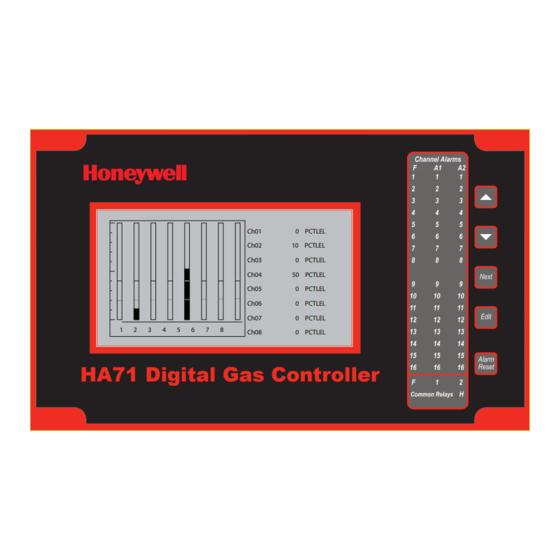
Page 7: Bar Graphs Screen
) is for powering HA71 Digital Gas Controller and MIN indicates peak to peak the HA71 and up to 16 detectors. A minimum of 5 watts per channel excursions over the one hour period is available for powering of external transmitters. -
Page 8: Relays
1.2.8 Non-Intrusive Magnetic Keypad Common relays are standard for ALARM 1, ALARM 2, FAULT and The HA71 operator interface includes five front panel touch keys. A HORN. Discrete relays are optional. All relays are rated at 5 Amp for magnetic keypad option offers these five keys with adjacent magnetic 28 VDC and 250 ~VAC RESISTIVE loads. -
Page 9: Basic Operation
HA71 Digital Gas Controller 2 Basic Operation HA71 Technical Manual Revision 3 (04/08) -
Page 10: Setup Menu Configuration
HA71 Digital Gas Controller 2.0 Basic Operation 2.1 Setup Menu Configuration The HA71 offers 3 graphic screens for viewing monitored data and Variables inside system and channel menu trees allow optimum HA71 a Set-Up menu screen for operator interface to configuration menus. -
Page 11: Channel Configuration Menus
HA71 Digital Gas Controller 2.2 Channel Configuration Menus 2.2.1 Channel Setup Entry Menu The entry menu shown on the left side of Figure 2-2 allows access to Figure 2-2 illustrates the menu tree for configuring Channel variables. all configuration variables for the selected channel. These are, Alarm These items affect only the specific channel selected. -
Page 12: Alarm 3 / Fault Alarm Menu
HA71 Digital Gas Controller • ON DELAY / OFF DELAY entries allow ON and OFF time The fault out of range threshold for the channel is the most recent Fault delays affecting how long the setpoint must be surpassed before trip point entered prior to changing the menu to Alarm 3. -
Page 13: Min/Max Raw Counts Menu
Input option described in section 3.1.3. This application requires the on the bottom of the screen displays actual raw A/D counts currently HA71 to be used as the calibration point since the sensors have no being read by this channel. This reading may be used to test the input zero or span controls. -
Page 14: Marker Menus
Calibrate 80.00 80.00 90.00 90.00 such events (see Figure 2-6). While active, the HA71 displays a 6-digit Entry menu Linearization menu ASCII message to indicate the special event and if equipped with Figure 2-6. Linearization Menu 10-0167 4-20mA output option, the HA71 also transmits the same <4mA value. -
Page 15: Input Measurement Range
HA71 Digital Gas Controller 2.2.10 Input Measurement Range to be activated, the HA71 may be set for 8 channel mode, deactivating channels 9-16. This is done in the System Setup menu described in The ZERO / SPAN entries allow configuration of the measurement Section 2.3. -
Page 16: System Configuration Menus
Some items needing configuration are not specific to a channel but may be monitored by recording zero and span readings at Unity Gain affect the entire HA71 system. when it is new, and again at later dates when degradation may have These are located in the system occurred. -
Page 17: Common Alarm Relays 1 And 2
CAutIoN Fault relay is always failsafe and may be monitored separately to indicate loss of power conditions in many applications. Read this section carefully and test all settings by simulating HA71 • A1 and A2 Votes allows creation of logical AND function input conditions that should activate these alarm relays! equations that control common relay 1 &... -
Page 18: 10-0195 Discrete Relay "Failsafe" Mode
2.3.3 Common Horn Relay and Local Piezo 10-0195 Discrete relay options may also be configured to function in The HA71 is equipped with a low decibel audible piezo which chirps when keys are pressed and may be configured to audibly indicate a Failsafe mode using the System Setup menu shown in Figure 2-11. -
Page 19: Modbus ® Master / Slave Serial Port Menus
8 or 16 channels. If 8 channels are selected by this menu they automatically (all channels are displayed on the Bar Graphs are channels 1-8 and 9-16 are disabled. One way HA71 cost is kept low screen). is Input / Output option PCB’s are arranged into groups of 8 channels. -
Page 20: Authorization Mode
HA71 Digital Gas Controller 2.4 Authorization Mode A password entered in the AUTHORIZATION menu allows locking all menus. Viewing menus is not denied but attempts to edit variables flashes the Locked message on the LCD. Authorized individuals locking the system should first enter a name, phone #, or other contact information into the 10 digit field. -
Page 21: Main I/O Interface Pcb
HA71 Digital Gas Controller 3 Main I/O Interface PCB HA71 Technical Manual Revision 3 (04/08) - Page 22 3.0 Main I/O Interface PCB J1 is 26 pin ribbon to main controller The most basic HA71 Controller requires only the I/O PCB shown in Spare shorting strips Figure 3-1 for interfacing to field wiring. The HA71 primary power supply is applied to terminals 9 and 11 of TB2.
-
Page 23: Input / Output Optional Pcbs
ANALOG ANALOG ANALOG ALARM2 assemblies are required for 16 connectors used to add option INPUT INPUT OUTPUT OUTPUT RELAY channels. PCB assemblies to the HA71. 9-16 9-16 FOUND FOUND FOUND FOUND FOUND ALARM2 INPUT 9-16 FOUND PRESS NEXT KEY TO EXIT Figure 3-2. -
Page 24: Optional Discrete Relay Pcb
J3. However, I C cables are limited in ability to carry this power further than a few feet without a significant voltage drop. Some HA71 5 amp form C dry contacts. Contacts are unfused. Switching applications with relays for all 48 alarms may require up to 6 boards. -
Page 25: Optional *Bridge Sensor Input Board
An optional 8-channel, 12 bit Bridge Sensor Input board allows these terminals 1 and 2 as shown in Figure 3-5. Suitable fused power popular gas detectors to be connected directly to the HA71 without is available from the Main I/O board’s TB2 terminal 10 & 12 additional signal conditioning or transmitters. - Page 26 LOW and MED jumpers together provide a gain of 28. Initial setup is now complete and normally only requires repeating if a sensor is replaced. Final calibration of this channel may now be performed using the HA71’s electronic Cal Mode feature described Section 2.2.1.
-
Page 27: Optional Rtd / 4-20Ma Analog Input Board
16 channels allows these popular temperature sensors to be connected directly J1 and J2 are interchangeable I to the HA71 without additional signal conditioning or transmitters. A JP1-JP8 work with JP9-JP16 to connectors used to add option PCB determine if a channel accepts a... -
Page 28: Optional 4-20Ma Analog Output Board
4mA for 0% readings and 20mA for 100% readings. Loop drive 2 PCB assemblies are required for 16 channels. capability depends upon the level of the HA71’s primary DC power supply. With at least 20 volts DC primary power they are capable of J1 & J2 are interchangable I2C connectors used to add option driving 20mA through a 750 ohm load. -
Page 29: Optional Clock/Printer Interface Board
Examples of printed alarm events are shown below. The format of each event, from left to right, is DATE, TIME, 16 character ASCII channel ID from the HA71, HA71 channel #, alarm #, IN or OUT status. A buffer in the HA71 retains the most recent 30 – 35 printed events. -
Page 30: Clock / Printer System Set-Up Menu
Figure 3-9. Date / Time menu providing inputs to the HA71. A 150 watt AC / DC power supply may be entries allow setting of correct local time and date. The ALARM included for these applications (115VAC or 230 VAC selected via slide PRINT ON/OFF entry allows printing to be discontinued if turned to switch). -
Page 31: System Diagnostics
HA71 Digital Gas Controller 4 System Diagnostics HA71 Technical Manual Revision 3 (04/08) - Page 32 HA71 Digital Gas Controller 4.0 System Diagnostics A System Diagnostic Mode shown in Figures 4-1 and 4-2 may be entered during normal operation from the Setup menu. The entry menu indicates firmware revision and offers useful routines for testing front panel LED’s, relays, serial ports and analog I/O.
- Page 33 HA71 Digital Gas Controller Figure 4-2. System Diagnostic Mode (Part 2) HA71 Technical Manual Revision 3 (04/08)
-
Page 34: Modbus
HA71 Digital Gas Controller ® 5 Modbus RS-485 Ports HA71 Technical Manual Revision 3 (04/08) -
Page 35: Modbus Slave Register Locations
The HA71 is equipped with Master (COMM 1), and Slave (COMM 2), Modbus ® RTU ports. Port configurations are described in Sections 2.2 of this manual. This section defines register locations of data available via the HA71 slave port. ® 5.1 Modbus Slave Register Locations The following table describes the HA71’s Modbus... - Page 36 HA71 Digital Gas Controller Six character EUNITS tag: Type Channel First Last Read FC Write FC Notes EUNITS 40529 40531 2 Characters per Register; 3 Registers per Channel EUNITS 40532 40534 2 Characters per Register; 3 Registers per Channel EUNITS 40535 40537 2 Characters per Register;...
- Page 37 HA71 Digital Gas Controller Six character Value ASCII string: Type Channel First Last Read FC Write FC Notes ASCII Value 40577 40579 2 Characters per Register; 3 Registers per Channel ASCII Value 40580 40582 2 Characters per Register; 3 Registers per Channel...
- Page 38 HA71 Digital Gas Controller Analog Output: Notes: 12 bit integer for Channel Reading value = 800 counts = zero value, 4000 counts = 100% value. Type Channel First Last Read FC Write FC Notes Channel Reading 1-16 31001 31016 12bit integer Channel Status words contain configuration and status bits for a channel.
- Page 39 HA71 Digital Gas Controller Alarm status words are bits packed into 16 bit integer where lsb = channel 1 alarm status and msb = channel 16 alarm status. Alarm status (bit = 1 indicates alarm is active): Type Channel First...
- Page 40 HA71 Digital Gas Controller Memory Discretes: Notes: May be read as single discrete or packed with multiple register read. Type Channel First Last Read FC Write FC Notes Channel Alarm 1 1-16 12001-16 discrete, may be packed Type Channel First...
- Page 41 HA71 Digital Gas Controller 24 Hour Trend Database: The 24 hour MAX, MIN and AVERAGE trend data may be retrieved over the Modbus ® serial interface. Each channel consists of 240 MAX, MIN and AVERAGE values, or, one value for every 1/10 hour (6 minutes). Since there are 16 channels this database equals 3,840 registers in addresses 33017-36857.
-
Page 42: Ha71 Enclosures
HA71 Digital Gas Controllers 6 HA71 Enclosures HA71 Technical Manual Revision 3 (04/08) -
Page 43: Ha71Pm Panel / Rack Mount Enclosure
HA71 Digital Gas Controller 6.0 HA71 Enclosures 6.1 HA71PM Panel / Rack Mount Enclosure The HA71PM shown in Figure 6-1 is a half width 19” rack enclosure. It is supplied with hardware that allows mounting in either a full width 19”... -
Page 44: Ha71N4 Nema 4X Fiberglass Wall Mount Encl
HA71 Digital Gas Controller 6.2 HA71N4 NEMA 4X Fiberglass Wall Mount Enclosure The HA71N4 shown in Figure 6-2 is a fiberglass NEMA 4X wall mount enclosure. Seven, 8 channel I/O option PCB’s, such as analog input or discrete relays, may be mounted inside this enclosure. It is suitable for mounting outdoors but an above mounted weather deflector shield is recommended. - Page 45 HA71 Digital Gas Controller Figure 6-3. Grounding Illustration HA71 Technical Manual Revision 3 (04/08)
-
Page 46: Ha71Ss Nema 4X 316 Stainless Steel Wall Mount Encl
HA71 Digital Gas Controller 6.3 HA71SS NEMA 4X 316 Stainless Steel Wall Mount Enclosure The HA71SS shown in Figure 6-4 is a 316 stainless steel NEMA 4X wall mount enclosure. Seven, 8 channel I/O option PCB’s, such as analog input or discrete relays, may be mounted inside this enclosure. It is suitable for mounting outdoors but an above mounted weather deflector shield is recommended. -
Page 47: Ha71Xp Nema 7 Explosion-Proof Wall Mount Encl
HA71 Digital Gas Controller 6.4 HA71XP NEMA 7 Explosion-Proof Wall Mount Enclosure The HA71XP shown in Figure 6-5 is an aluminum NEMA 4X/7 wall mount enclosure designed for mounting into DIV 1 and 2 Groups B,C,D potentially hazardous areas. Eleven, 8 channel I/O option PCB’s, such as analog inputs or discrete relays, may be mounted inside this enclosure. -
Page 48: Ha71 Main I/O And Option Pcb Footprint Dimensions
HA71 Digital Gas Controller 6.5 HA71 Main I/O and Option PCB Footprint Dimensions HA71 controllers have virtually unlimited possibilities for configuration of options such as analog I/O, discrete relays, printer interface and others. All HA71 enclosure styles require the Main I/O PCB (Figure 3-1) but also support the mounting of additional option PCB’s as described below:... -
Page 49: A Ordering Information
HA71 Digital Gas Controller A Ordering Information HA71 Technical Manual Revision 3 (04/08) - Page 50 RS-485 I/O interfaces and has 5 amp form C relays for Alarm 1, Alarm 2, Fail and Horn alarm conditions. Analog and Discrete I/O is available by addition of the appropriate OPTION boards interfaced to the HA71 via an I2C serial expansion bus. Factory packaging of the HA71SM within a rack/panel mount enclosure (HA71PM), a NEMA 4X enclosure (HA71N4) and a NEMA 7 explosion-proof enclosure (HA71XP) is also available.
- Page 51 Replacement Main I/O PCB for HA71PM (ribbon connector on circuit side of PCB) 10-0006 Replacement HA71 Flat Panel LCD Module 10-0185 Replacement Complete HA71 Front Panel Electronic Nest Assembly Including 10-0006 LCD 10-0231 Replacement HA71 Front Graphic Panel 1000-1992 Replacement Main I/O PCB Fuse; 20mm / 2 amp...
-
Page 52: B Warranty
HA71 Digital Gas Controller B Warranty HA71 Technical Manual Revision 3 (04/08) -
Page 53: Honeywell Analytics Warranty Statement
HA71 Digital Gas Controller Honeywell Analytics Warranty Statement Honeywell Analytics shall not be liable for any loss or damage whatsoever or howsoever occasioned which may be a direct or indirect All products are designed and manufactured to the latest internationally... - Page 54 This publication is not intended to form the basis of a contract. Wilstrasse 11-U11 CH-8610 Uster Switzerland Tel: +41 (0)1 943 4300 Fax: +41 (0)1 943 4398 [email protected] Technical Services [email protected] 1998M0650 Rev 3 www.honeywell.com April 2008 © 2008 Honeywell Analytics...