
Related Manuals for Omron CS1W-CT041


Summary of Contents for Omron CS1W-CT041
- Page 1 Cat. No. W902-E2-03 CS1W-CT021 CS1W-CT041 High-speed Counter Units OPERATION MANUAL...
- Page 2 CS1W-CT021/CT041 High-speed Counter Units Operation Manual Revised August 2004...
- Page 3 !"...
- Page 4 OMRON Product References All OMRON products are capitalised in this manual. The word “Unit” is also capitalised when it refers to an OMRON product, regardless of whether or not it appears in the proper name of the product.
- Page 5 "!
-
Page 6: Table Of Contents
TABLE OF CONTENTS PRECAUTIONS ....................Intended Audience................................ xii General Precautions..............................xii Safety Precautions ................................ xii Operating Environment Precautions..........................xiii Application Precautions............................... xiv EC Directives................................xvi SECTION 1 Introduction....................... Features and Functions ............................Basic Configuration..............................Specifications and Characteristics ........................... Quick Start Up Reference Guide ..........................Operating Procedure Guidelines.......................... - Page 7 Maintenance and Inspection............................ SECTION 6 Application Examples ..................151 Flow Control ................................Length Measurement............................... Positioning................................CAM-positioning ..............................Speed Control................................Appendices Appendix A Comparison with C200H-CT021 ....................Appendix B Using Terminal Block Units with Screw-terminals................. Appendix C Assigning External Interrupt Tasks to Outputs ................Appendix D Description of the Response Time....................
- Page 8 This manual describes the installation and operation of the CS1W-CT021/CT041 High-speed Counter Units and includes the sections described below. Both the CS1W-CT021 and the CS1W-CT041 High- speed Counter Units are identical and differ only in the number of Counters that they are equipped with, 2 and 4 Counters respectively.
- Page 9 !WARNING Failure to read and understand the information provided in this manual may result in personal injury or death, damage to the product, or product failure. Please read each section in its entirety and be sure you understand the informa- tion provided in the section and related sections before attempting any of the pro- cedures or operations given.
-
Page 10: Precautions
!"#$%&'()*+ PRECAUTIONS This section provides general precautions for using the Programmable Controller (PLC) and the High-speed Counter Unit. The information contained in this section is important for the safe and reliable application of the High-speed Counter Unit. You must read this section and understand the information contained before attempting to set up or operate a High-speed Counter Unit and PLC system. -
Page 11: Intended Audience
It is extremely important that a PLC and all PLC Units be used for the specified purpose and under the specified conditions, especially in applications that can directly or indirectly affect human life. You must consult with your OMRON repre- sentative before applying a PLC system to the above mentioned applications. -
Page 12: Operating Environment Precautions
!"#$%&'()*+ Operating Environment Precautions !WARNING Do not touch any of the terminals or terminal blocks while the power is being supplied. Doing so may result in electric shock. !WARNING Do not attempt to disassemble, repair, or modify any Units. Any attempt to do so may result in malfunction, fire, or electric shock. -
Page 13: Application Precautions
!"#$%&'()*+ Application Precautions Application Precautions Observe the following precautions when using the High-speed Counter Unit or the PLC. !WARNING Failure to comply with the following precautions could lead to serious or possibly fatal injury. Always follow these precautions. • Always ground the system with 100 Ω or less when installing the system, to pro- tect against electrical shock. - Page 14 !"#$%&'()*+ Application Precautions • Install the Units properly as specified in the operation manuals. Improper !Caution installation of the Units may result in malfunction. • Be sure that all the mounting screws, terminal screws, and cable connector screws are tightened to the torque specified in the relevant manuals. Incorrect tightening torque may result in malfunction.
-
Page 15: Ec Directives
Concepts EMC Directives OMRON devices that comply with EC Directives also conform to the related EMC standards so that they can be more easily built into other devices or the overall machine. The actual products have been checked for conformity to EMC stand- ards (see the following note). -
Page 16: Introduction
SECTION 1 Introduction This section gives specifications of the CS1W-CT021/CT041 and a brief description of the functions and features of the Unit and the areas of application. Features and Functions............................Basic Configuration..............................Specifications and Characteristics........................... 1-3-1 General Specifications ..........................1-3-2 Functional Specifications .......................... -
Page 17: Features And Functions
,#%'&"#+-%*.-,&*$'()*+ Section 1-1 Features and Functions The CS1W-CT021 and CT041 High-speed Counter Units are equipped with 2 and 4 Counters respectively, all able to count over a maximum binary range of 32-bits. Accepting input pulse frequencies of up to 500 kHz allows precise control of fast motions. - Page 18 ,#%'&"#+-%*.-,&*$'()*+ Section 1-1 Digital Input Function The Unit is equipped with 4 Digital Inputs (I0, I1, I2 and I3) that can be freely assigned to any Counter. To meet the requirements of your application every Dig- ital Input can be configured according to one out of 17 available functions. The functions make it possible to use a Digital Input with Gate-, Preset-, Reset- or Cap- ture Functionality (among other functions).
- Page 19 ,#%'&"#+-%*.-,&*$'()*+ Section 1-1 Noise Filtering For the purpose of suppressing noise on the signal lines A and B of every Counter and on the Digital Input lines noise filters can be used. Noise filters can be config- ured independently from each other for Counters 1&2, Counters 3&4, Digital Inputs 0&1 and Digital Inputs 2&3.
-
Page 20: Basic Configuration
/%+($-0)*1(2&"%'()* Section 1-2 Basic Configuration Typical applicable Sensors for Digital Inputs: Typical applicable Actuators for Digital Outputs: Photo Electric Relais Sensor Lamp Push Button Limit Switch Motor Interface ON/OFF High/Low Speed Forward/Reverse Proximity Switch Brake ON/OFF Other Actuators Other Sensors Typical applicable Pulse Generators for Counter Inputs: Incremental... - Page 21 1. Directly connecting the wires by soldering them to the external connector. 2. Indirectly connecting the wires by connecting them to screw terminals on a Ter- minal Block Unit. The Omron Terminal Block Unit (XW2B-40G4 or XW2B- 40G5) is connected to the Unit via standard available Omron flat-cables (XW2Z-xxxB).
-
Page 22: Specifications And Characteristics
-20 to +75 °C Storage Temperature Humidity 10 to 90% without condensation Internal Current Consumption 450 mA (CS1W-CT041), 360 mA (CS1W-CT021) (at 5V via backplane) Dimensions (mm) 35 x 130 x 100 (W x H x D) Weight 245 g... -
Page 23: Functional Specifications
Item CS1W-CT021/CT041 • 2 run-time configurable Counters for the CS1W-CT021 Number of Counters • 4 run-time configurable Counters for the CS1W-CT041 • Simple Counter (refer to 3-2-1 "Simple Counter") Counter Type • Circular Counter (refer to 3-2-2 "Circular Counter") • Linear Counter (refer to 3-2-3 "Linear Counter") The Counter Type can be chosen by DIP switch at the back of the Unit. - Page 24 34#$(1($%'()*+-%*.-05%"%$'#"(+'($+ Section 1-3 Item CS1W-CT021/CT041 Output State Control On changing the Operating Mode of the PLC from RUN/MONITOR → PROGRAM, an I/O Bus Error or an Overflow/Underflow Error, the Digital Outputs can be configured to: • Continue automatic updating Output States •...
- Page 25 34#$(1($%'()*+-%*.-05%"%$'#"(+'($+ Section 1-3 Item CS1W-CT021/CT041 IORD- and IOWR-instructions Run-time configuration and operation of the High-speed Counter Unit is possible by using IORD- and IOWR-instructions. The following data can be read or written: • DM-configuration data* (refer to 4-5-1 "DM-data") • Range- and Comparison Data* (refer to 4-5-2 "Range- and Comparison data") •...
-
Page 26: Input Specifications
34#$(1($%'()*+-%*.-05%"%$'#"(+'($+ Section 1-3 1-3-3 Input Specifications Item Counter Inputs A and B Digital Inputs (I0, I1, I2 and I3) Input Voltage 24 VDC 12 VDC 5 VDC Line Driver 24 VDC (19.6 to 26.4 V) (9.8 to 13.2V) (4.5 to 5.5V) (19.6 to 26.4 V) Input Current 8 mA... - Page 27 34#$(1($%'()*+-%*.-05%"%$'#"(+'($+ Section 1-3 Counter Inputs A, B, Z and Digital Inputs 5/12/24V input signals RS-422 Line Driver signals Counter inputs A and B Counter inputs A and B Input pulses with a duty factor of 50% Input pulses with a duty factor of 50% Counter Inputs A, B and Z signals RS-422 Line Driver signals...
-
Page 28: Output Specifications
34#$(1($%'()*+-%*.-05%"%$'#"(+'($+ Section 1-3 want to generate count pulses with higher frequencies, you should use a different type of encoder (e.g. E6B2-CWZ1X with Line Driver output or a fast push-pull 24 V encoder, e.g. E6C2-CWZ5GH) or reduce the length of the encoder cable. 1-3-4 Output Specifications Item... -
Page 29: Quick Start Up Reference Guide
6&($7-3'%"'-84-9#1#"#*$#-:&(.# Section 1-4 Power Supply The power supplied to the Unit, to feed the Digital Outputs, has to be supplied Characteristics externally and should be a double insulated class II (over-voltage) type with rat- ings from 12 to 24 VDC (10.2 to 26.4 VDC). Characteristics of the Power Supply Input circuitry are summarized in the following table. - Page 30 6&($7-3'%"'-84-9#1#"#*$#-:&(.# Section 1-4 Exchanging data with CPU The diagram below shows you all the functional blocks that the Unit has available to you to exchange data with the CS1-CPU (refer to "Exchanging Data with CPU"). CS1W-CT021/ CS1-CPU CT041 IOWR IORD Interrupts Unit Output Pattern Interrupts...
- Page 31 6&($7-3'%"'-84-9#1#"#*$#-:&(.# Section 1-4 Simple Counter Circular / Linear Counter Reference section Input Signal Types • Phase Differential (x1) (=default) • Phase Differential (x1, x2, x4) 3-3-1 • Up & Down 3-3-2 • Pulse & Direction 3-3-3 Counter Control using CIO- software bits •...
- Page 32 6&($7-3'%"'-84-9#1#"#*$#-:&(.# Section 1-4 Simple Counter Circular / Linear Counter Reference section Reset Signals • Software Reset Bit • Software Reset Bit • Digital Input • Z-signal Programmable Output Pulses 3-7-1 • No (=default) • Yes 3-7-1 Rate Measurement 3-7-2 • No (=default) •...
-
Page 33: Configuring The High-Speed Counter Unit
6&($7-3'%"'-84-9#1#"#*$#-:&(.# Section 1-4 1-4-1 Configuring the High-speed Counter Unit Configuration Configuring every Counter starts with choosing the Counter Type (Simple, Circu- lar or Linear). Simple Counter For Simple Counters you do not have to make any DM-configuration settings, since for Simple Counters all default (DM-) settings are used. You can choose to use Simple Counters if you intend to use the Counter only with basic counting functionality (refer to 3-2-1 "Simple Counter"... - Page 34 400 DM-words can be used as work-words in the PLC Ladder Pro- gram. CS1W-CT041: For the CT041 the Special I/O Unit DM-Area is divided in an area of 30 words to make the General Unit Settings and 4 blocks of 45 DM-words each used to make the Counter Specific Settings, which are unique for every Counter.
-
Page 35: Operating Procedure Guidelines
;4#"%'(*2-!")$#.&"#-:&(.#<(*#+ Section 1-5 Operating Procedure Guidelines The DIP switch at the back of the Unit can be used to operate every Counter as Simple Counter or as Circular/Linear Counter. Setting the DIP switch in the appro- priate position defines the Counter Type. The Operation Procedure Guidelines consists of 5 steps. - Page 36 ;4#"%'(*2-!")$#.&"#-:&(.#<(*#+ Section 1-5 3. Install and wire the Unit. Refer to 2-2 "Installation" and 2-3 "Wiring" for further details. 4. Turn ON the Power to the PLC. Power ON 5. Create the I/O table. The I/O table can be created by using CX-Programmer Support Software or a Programming Console.
- Page 37 ;4#"%'(*2-!")$#.&"#-:&(.#<(*#+ Section 1-5 Configuration 1 All Counters as Simple Counters: 1, 2, 3… 1. No (DM-) configuration settings can be made. The Unit is ready to count and will use all default DM-values. All data related to the Simple Counter is now being exchanged between the PLC and the Unit in CIO-memory and available for usage in the PLC Ladder Program.
-
Page 38: Application Areas
=44<($%'()*-="#%+ Section 1-6 Note For using Simple Counters you do not have to clear the corresponding DM-set- tings to zero (=0000), since the Unit does not use this information and always uses the default (=0000) settings. Application Areas The main application areas of the High-speed Counter Unit is where signals with high frequencies are counted and high-speed responses have to be triggered at predefined Counter Values. -
Page 40: Components, Installation And Wiring
SECTION 2 Components, Installation and Wiring This section provides details of the components, switch settings and other information required to install and operate CS1W-CT021/CT041 High-speed Counter Units. Components and Switch Settings..........................2-1-1 Components ............................... 2-1-2 Indicators ..............................2-1-3 Counter Type Switch ..........................2-1-4 Machine Number Switch ........................... -
Page 41: Components And Switch Settings
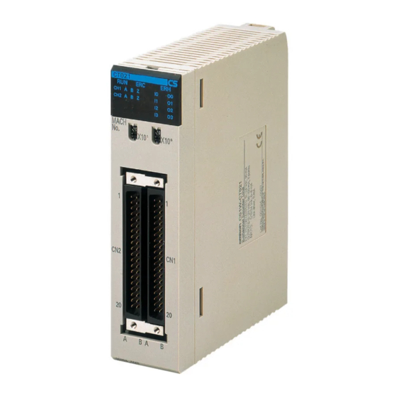
0)>4)*#*'+-%*.-3?('$5-3#''(*2+ Section 2-1 Components and Switch Settings 2-1-1 Components Front and Rear View CT021 CT041 Indicators Counter Mode MACH Machine Switch MACH Number Switch 130 mm Connector 35 mm 35 mm 35 mm Side View Hook 130 mm Connector 100 mm... -
Page 42: Indicators
0)>4)*#*'+-%*.-3?('$5-3#''(*2+ Section 2-1 2-1-2 Indicators The indicators on the LED-display show the operating status of the Unit. The fol- lowing table shows the meaning of the indicators. Colour State Description Green Unit is in operation (i.e. Unit has initialised normally after (re-) starting the Unit). Unit is not in operation (i.e. -
Page 43: Counter Type Switch
Simple Counter Circular/Linear Counter Simple Counter * CS1W-CT041 High-speed Counter Unit only. After having set the DIP switch of the Counter to ON, further selection between Circular and Linear Counter, is done by DM-setting. Counters that are configured for Circular/Linear Counter can make use of all the features that the High-speed Counter Unit offers. -
Page 44: Machine Number Switch
0)>4)*#*'+-%*.-3?('$5-3#''(*2+ Section 2-1 2-1-4 Machine Number Switch The CPU Unit and the High-speed Counter Unit exchange data via the Special I/O Unit Area (CIO) and the Special I/O Unit DM Area. The High-speed Counter Unit is allocated the words for 4 Units. This means that 40 words in the Special I/O Unit Area (CIO) and 400 words in the Special I/O Unit DM Area are allocated. -
Page 45: Installation
@*+'%<<%'()* Section 2-2 Note 1. If two or more Special I/O Units are assigned the same Machine Number, a fatal error “Unit No. Duplication Error” (in the PLC-CPU) will be generated (A40113 will turn ON) and the PLC will not operate. 2. - Page 46 @*+'%<<%'()* Section 2-2 2. While making sure to align the Unit properly with the (bus-) connectors, tighten the mounting screws securely using a flat-blade screwdriver with a maximum tightening torque of 0.4 Nm. Mounting screw Note To remove the Unit, first loosen the mounting screws. Leave enough space below each Rack, as shown in the following diagram to be able to mount or remove Units in a later stage.
-
Page 47: Wiring
CH4: 24V CH3: 5V CH3: 24V * CS1W-CT041 High-speed Counter Unit only. Power Supply External power has to be applied to the Power Supply pins in order to feed the Dig- ital Outputs. Depending on what your application requires you can apply an exter- nal voltage between 12 to 24VDC. -
Page 48: Connector Wiring Methods
Counter. To the CS1W-CT021, 5VDC and 12VDC signals can be applied only to Counters 1 and 2 respectively. The CS1W-CT041 allows connecting 5VDC and 12VDC signals only to Counter 1 and 3 and Counter 2 and 4 respectively. The fol-... - Page 49 A("(*2 Section 2-3 2. Indirectly connecting the wires and cables to the screw terminals of a Terminal Block Unit. The Terminal Block Unit is connected to the Unit with a standard (flat-) cable. Both parts can be ordered separately. External Connector The connector has to be assembled from the separate parts that it exists of and that are supplied together with the Unit.
- Page 50 A("(*2 Section 2-3 Assembling Connectors Three, M2 pan-head screws (8 mm long) Two, M2.6 long screws Case One M2.6 pan-head screw (6 mm long) Connector jack Cable clamp Case One, M2.6 nut Three M2 nuts Note 1. The cross section of the signal wires that can be connected to each soldering terminal must be ≤...
-
Page 51: Important Wiring Considerations
A("(*2 Section 2-3 The length of the cable is indicated by ‘xxx’ in centimetres. The following cables are available: • XW2Z-050B (0.5 m) • XW2Z-100B (1 m) • XW2Z-150B (1.5 m) • XW2Z-200B (2 m) • XW2Z-300B (3 m) • XW2Z-500B (5 m) The next figure shows how to use the Terminal Block Unit in a typical configuration together with the CS1W-CT021/CT041 High-speed Counter: Refer to Appendix B "Using Terminal Block Units with Screw-terminals"... -
Page 52: Internal Circuitry
A("(*2 Section 2-3 2-3-4 Internal Circuitry Digital Input Circuitry Digital Input IO: Digital Input I1: Digital Input I2: Digital Input I3: B5 (24V) B6 (24V) B5 (24V) B6 (24V) A5 (0V) A6 (0V) A5 (0V) A6 (0V) Connector Connector Counter Input Circuitry Counter 1: Counter 2: Counter 3:... - Page 53 A("(*2 Section 2-3 Digital Output Circuitry High-speed Counter Fuse B1 (CN1 and CN2): PS+: 12-24 V DC Power Supply for Digital Outputs O0 - O3 B2 (CN1): Digital Output O0 (PNP) B3 (CN1): Digital Output O1 (PNP) B2 (CN2): Digital Output O2 (PNP) B3 (CN2): Digital Output O3 (PNP) A2 (CN1): Digital Output O0 (NPN) A3 (CN1): Digital Output O1 (NPN)
-
Page 54: Digital I/O Circuit Configurations
A("(*2 Section 2-3 2-3-5 Digital I/O Circuit Configurations The following examples make clear how to wire the Digital Inputs and the Digital Outputs. 24 VDC NPN Sensor 24 V DC Power Supply + 24 V High-speed Counter Shielded twisted-pair cable NPN Sensor Digital Input I0 on Connector CN1 24 VDC PNP Sensor... - Page 55 A("(*2 Section 2-3 Wiring example NPN/PNP Digital Output 12 to 24 V DC Power Suply Fuse (1A) B1 (CN1 or CN2): PS+ -12 to 24 V Load Load B2 (CN1): O0 (PNP) B2 (CN2): O2 (PNP) A3 (CN1): O1 (NPN) A3 (CN2): O3 (NPN) Load Load...
-
Page 56: Counter Input Configurations
A("(*2 Section 2-3 2-3-6 Counter Input Configurations The following examples make clear how to wire the Counter Inputs in different con- figurations according to the output-driver of the encoder or proximity switch that you want to use. The configurations that are shown here, related to a specific out- put-driver, can also be referred to in case you want to use other pulse generating equipment with similar output-drivers. - Page 57 A("(*2 Section 2-3 5/12/24 VDC PNP Open Collector High-speed Counter Terminals (CN2) Black: Phase A B9 (Phase A 24V) A8 (Phase A 0V) Encoder White: Phase B B11 (Phase B 24V) A10 (Phase B 0V) Orange: Phase Z B13 (Phase Z 24V) A12 (Phase Z 0V) Counter 2 Brown: + Vcc...
- Page 58 A("(*2 Section 2-3 Line Driver (RS422) High-speed Counter Terminals (CN1) Black: Phase A+ B15 (Phase A+, LD+) Black/red: Phase A- A15 (Phase A-, LD-) Encoder White: Phase B+ B17 (Phase B+, LD+) White/red: Phase B- A17 (Phase B-, LD-) Orange: Phase Z+ B19 (Phase Z+, LD+) Orange/red: Phase Z- A19 (Phase Z-, LD-)
- Page 59 A("(*2 Section 2-3...
-
Page 60: Operation And Configuration
SECTION 3 Operation and Configuration This section describes how to configure the CS1-CT021/CT041 High-speed Counter Unit and how to operate the Unit according to the specific requirements of your application. Overview ................................. Counter Types ................................. 3-2-1 Simple Counter ............................3-2-2 Circular Counter ............................ -
Page 61: Overview
;B#"B(#? Section 3-1 Overview After you have installed and wired the CS1W-CT021/CT041 High-speed Counter Unit as described in 2-2 "Installation" and 2-3 "Wiring", you have to configure the Unit by making DM-settings. Only Counters that have been configured for Circular/ Linear Counter (corresponding DIP switch at the back of the Unit in the ON-posi- tion) can be DM-configured. -
Page 62: Counter Types
0)&*'#"-CD4#+ Section 3-2 Counter Types Every single Counter of the High-speed Counter Unit can be set independently to one of the following Counter Types (for an overview of the differences between Simple and Circular/Linear Counters refer to 1-4 "Quick Start Up Reference Guide"): •... - Page 63 0)&*'#"-CD4#+ Section 3-2 If you want to use all the available features and functions of the High-speed Coun- ter Unit you must configure a Counter not as Simple Counter but as Circular or Lin- ear Counter. For detailed information on Circular and Linear Counters refer to 3- 2-2 "Circular Counter"...
- Page 64 0)&*'#"-CD4#+ Section 3-2 Controlling Simple Simple Counters can be controlled from CIO. For an overview of all control bits Counters via CIO and words refer to 4-2-3 "CIO-Memory Mapping". The following gives a detailed description of all the features and functions for Sim- ple Counters that are available in CIO: 32 Bits Counting Range A Simple Counter has the full counting range (=32 bits) available to count up- or...
- Page 65 0)&*'#"-CD4#+ Section 3-2 CNT1: CNT2: CNT3: CNT4: 15 14 13 12 11 10 9 8 n+11 Open Gate: 0→1 = Open Gate Close Gate: 0→1 = Close Gate A rising edge of the "Open Gate Bit" opens the Gate regardless of the state of the "Close Gate Bit".
- Page 66 0)&*'#"-CD4#+ Section 3-2 Forcing ON/OFF Digital After you have set the Automatic/Manual Selection bit to Manual Output Control Outputs (=1), the four Digital Outputs can be forced ON and OFF using the corresponding bits in CIO. General Setting: 15 14 13 12 11 10 9 8 O3 O2 O1 O0 Manual Output Control: 0 = Force Output OFF...
-
Page 67: Circular Counter
0)&*'#"-CD4#+ Section 3-2 3-2-2 Circular Counter Configuring Circular Counters CNT1: CNT2: CNT3: CNT4: 15 14 13 12 11 10 9 8 m+30 m+75 m+120 m+165 Counter Type: 0 = Circular Counter A Circular Counter has 32-bits (the full counting range) available to count up- or downwards over the positive counting range between 0 and the Upper Count Limit. -
Page 68: Linear Counter
0)&*'#"-CD4#+ Section 3-2 3-2-3 Linear Counter Configuring Linear Counters CNT1: CNT2: CNT3: CNT4: 15 14 13 12 11 10 9 8 m+30 m+75 m+120 m+165 Counter Type: 1 = Linear Counter A Linear Counter has the full counting range (=32 bits) available to count up- or downwards over the positive and negative counting range between the Minimum Count Limit and the Maximum Count Limit. - Page 69 0)&*'#"-CD4#+ Section 3-2 Configuring Upper and The Upper Count Limit must be positive and the Lower Count Limit must be neg- Lower Count Limits ative (zero is not allowed as Count Limit). To set the Maximum and Minimum Count Limits refer to the following: CNT1: CNT2: CNT3:...
-
Page 70: Input Signal Types
@*4&'-3(2*%<-CD4#+ Section 3-3 Input Signal Types The type of input you require for your application is selected by means of four bits in the Signal Type Word in DM. For every Counter the Signal Type can be selected individually. 15 14 13 12 11 10 9 8 CNT1: CNT2: CNT3:... -
Page 71: Up & Down
@*4&'-3(2*%<-CD4#+ Section 3-3 Multiplication x1 By default the Counter is configured for Multiplication by 1. If the counter is up- counting (signal A leads to signal B) pulses are taken into account by the Counter on the rising edges of signal A. If the Counter is down-counting pulses are taken into account on the falling edges of input A. -
Page 72: Pulse & Direction
@*4&'-3(2*%<-CD4#+ Section 3-3 3-3-3 Pulse & Direction In this configuration, count pulses are applied to input A. The direction of counting is controlled by the level of the signal applied to input B. If input B is high, the Counter increments on the rising edges of input A. If input B is low, the Counter decrements on the rising edges of input A. -
Page 73: Digital Input Functions
E(2('%<-@*4&'-,&*$'()*+ Section 3-4 Digital Input Functions Assigning multiple Digital The High-speed Counter Unit is equipped with four Digital Inputs allowing every Inputs to single Counters Counter to be controlled by a Digital Input. For applications that require a Counter to be controlled by more than one Digital Input, multiple Digital Inputs (i) can be assigned to a Counter (i ≤... - Page 74 E(2('%<-@*4&'-,&*$'()*+ Section 3-4 Digital Input Functions Furthermore, the function of every Digital Input can be selected from one out of 17 available functions. Every function performs its unique action on the Counter to which it is assigned. The action can be performed on the rising or on the falling edge of the Digital Input signal.
- Page 75 E(2('%<-@*4&'-,&*$'()*+ Section 3-4 Gate Function The Gate Function should be assigned to a Digital Input in case you want to use that Digital Input as a Gate. When the Gate is open, the Counter is able to count pulses. When the Gate is closed, the Counter will not count pulses. The Positive Gate Function (01) results in an open Gate when the level of the signal applied to the Digital Input is high and a closed Gate when the level of the signal applied to the Digital Input is low.
- Page 76 E(2('%<-@*4&'-,&*$'()*+ Section 3-4 the Preset Value at a rising edge of the Preset Counter Bit of the corresponding Counter. 15 14 13 12 11 10 9 8 CNT1: CNT2: CNT3: CNT4: n+11 Preset Counter: 0→1 = Preset Counter 15 14 13 12 11 10 9 8 CNT1: CNT2: CNT3:...
- Page 77 E(2('%<-@*4&'-,&*$'()*+ Section 3-4 Capture Function A Digital Input configured to have Capture functionality will capture the current Counter Value into the Capture Register on a rising edge (Capture Rising Edge, Function 07) or falling edge (Capture Falling Edge, Function 08) of the Digital Input signal.
- Page 78 E(2('%<-@*4&'-,&*$'()*+ Section 3-4 Stop, Capture, Reset and A Digital Input configured to have Stop, Capture, Reset and Continue functionality Continue will Stop the Counter (= close the Gate) and Capture the Counter Value into the Capture Register on a rising edge of the signal applied to the Digital Input (Stop, Capture, Reset and Continue, Function 11).
- Page 79 E(2('%<-@*4&'-,&*$'()*+ Section 3-4 Enable, Disable Reset A Digital Input configured to have Enable Reset Functionality (Function 15) or Dis- able Reset Functionality (Function 16) can be used to Enable/Disable resetting a Counter by an external reset signal. The external reset signal can originate from another Digital Input that is configured to have reset functionality (Function 5, 6, 11, 12, 13 or 14) or from the Z-input.
-
Page 80: Output Control
;&'4&'-0)*'")< Section 3-5 Counting Direction For every Counter the (up or down) counting direction is indicated and can be used in the Ladder Program. CNT1: CNT2: CNT3: CNT4: 15 14 13 12 11 10 9 8 n+24 n+29 n+34 n+39 Gate Open/Closed: 0 = Gate Closed 1 = Gate Open... - Page 81 ;&'4&'-0)*'")< Section 3-5 Unit Output Pattern Both in Range and Comparison Mode the 32 Outputs of the Unit are represented by the Unit Output Pattern. The Unit uses the Unit Output Pattern internally to con- trol the Outputs. The Unit Output Pattern consists of 28 Soft Outputs and 4 Digital Outputs.
-
Page 82: Range Mode
;&'4&'-0)*'")< Section 3-5 3-5-1 Range Mode If the Unit is configured to control the Outputs in Range Mode, this Mode can be applied to Circular Counters or Linear Counters (refer to 3-2-2 "Circular Counter" and 3-2-3 "Linear Counter" for more information). Example Range Mode with Linear Counter Minimum Count Limit... - Page 83 ;&'4&'-0)*'")< Section 3-5 Example Range Mode with Circular Counter Range 2 Maximum Count Limit 4,294,967,295 (=00000000 ) (=FFFFFFFF Range 1 Rollover Range 0 Range 3 Counter Value Range Lower Range Limit Upper Range Limit Output ON 60,000 80,500 45000 1, 3 37,000,000 6000 99,000...
-
Page 84: Range Mode Overview
;&'4&'-0)*'")< Section 3-5 3-5-1-1 Range Mode Overview The following figure gives an overview on configuring Counters in Range Mode. Range 0 Counter 1 Upper Range Limit Output Pattern Lower Range Limit Output Pattern Range 31 Upper Range Limit Output Pattern Lower Range Limit Range 0 Counter 2... -
Page 85: Configuration And Operation In Range Mode
;&'4&'-0)*'")< Section 3-5 3-5-1-2 Configuration and operation in Range Mode Specifying Range-Data In Range Mode every Counter can be assigned up to a maximum of 32 Ranges. The Data of every Range is contained by 3 double words: • Lower Range Limit, specifying the Lower Limit of the Range •... - Page 86 ;&'4&'-0)*'")< Section 3-5 A Range becomes active if: Lower Range Limit ≤ Counter Value ≤ Upper Range Reflecting Active / Not Active Ranges Limit. Whether or not a Range is active is reflected in CIO for each Counter. CNT1: CNT2: CNT3: CNT4: 15 14 13 12 11 10 9 8...
-
Page 87: Comparison Mode
;&'4&'-0)*'")< Section 3-5 Note 1. The Counter Output Patterns of Counters which are configured to use no (i.e. zero) Ranges, are ignored in the AND-calculation of the Unit Output Pattern. Like this, Counters that you do not want to use, do not influence the AND-cal- culation of the Unit Output Pattern. - Page 88 ;&'4&'-0)*'")< Section 3-5 CV is crossed in the positive counting direction (+CV crossing) or negative count- ing direction (-CV crossing), one or multiple Outputs can be Set (S) or Reset (R). For example Output 0 is Set on crossing CV5 in the positive counting direction and Reset on crossing CV7 in the negative counting direction.
-
Page 89: Comparison Mode Overview
;&'4&'-0)*'")< Section 3-5 3-5-2-1 Comparison Mode Overview The following figure gives an overview on configuring Counters in Comparison Mode. Counter 1 +Set Pattern CV0 +Reset Pattern CV0 Comparison Value 0 -Set Pattern CV0 -Reset Pattern CV0 +Set Pattern CV31 +Reset Pattern CV31 Comparison Value 31 -Set Pattern CV31 -Reset Pattern CV31... -
Page 90: Configuration And Operation In Comparison Mode
;&'4&'-0)*'")< Section 3-5 3-5-2-2 Configuration and operation in Comparison Mode Specifying Comparison- In Comparison Mode every Counter can be assigned up to a maximum of 32 Com- Data parison Values. The Data of every Comparison Value (CV-Data) is contained by 5 double words: •... - Page 91 ;&'4&'-0)*'")< Section 3-5 Note 1. Multiple Comparison Values of a specific Counter may not have the same value. The Unit will generate an error if multiple CV’s have the same value (refer to 5-2 "Error codes" for more details). 2. CV-Data can also be changed on the fly. Refer to 4-3 "IOWR-Instruction" for more details.
-
Page 92: Manual Output Control
;&'4&'-0)*'")< Section 3-5 Updating Unit Output Besides by crossing CV’s the Unit Output Pattern can also be updated by a Preset Pattern with Preset or Reset or a Reset action. To trigger a Preset or Reset action refer to 3-4 "Digital Input Action Functions"... -
Page 93: Output Control Configuration
;&'4&'-0)*'")< Section 3-5 3-5-4 Output Control Configuration NPN or PNP Output Driver Every single Digital Output (0-3) can be used in a NPN- or PNP-configuration depending on your application needs. By setting the corresponding bit in DM a selection can be made between a NPN- or PNP Output Driver. By default the NPN Output Driver is selected. -
Page 94: Reset Signals
9#+#'-3(2*%<+ Section 3-6 Reset Signals For every Counter a reset of the Counter Value to zero can be triggered by the fol- lowing Sources: • Software Reset Bit • Digital Input • Z-signal In order for a Digital Input or the Z-Signal to trigger a Reset this must be enabled by the Software Reset Enable Bit. - Page 95 9#+#'-3(2*%<+ Section 3-6 Software Reset Enable Bit Resetting the Counter Value to zero by Digital Input or Z-Signal must be enabled. as Reset Enable Source Enabling can be done by setting the Software Reset Enable Bit in CIO for the cor- responding Counter to 1.
-
Page 96: Extra Functions
FG'"%-,&*$'()*+ Section 3-7 Extra Functions 3-7-1 Programmable Output Pulses Depending on the requirements of your application, the timing characteristics of the four Digital Outputs of the High-speed Counter Unit can be modified. The Unit can be either in Range Mode or in Comparison Mode. The following functionality can be assigned to the Digital Outputs: •... - Page 97 FG'"%-,&*$'()*+ Section 3-7 Output Pulse Duration A Digital Output that is configured to have an Output Pulse Duration turns ON immediately and will stay ON for the specified Pulse Duration. After the Pulse Duration has elapsed the Digital Output turns OFF. Note The status of the Outputs is reflected in CIO (words n+14, n+15).
-
Page 98: Rate Measurement
FG'"%-,&*$'()*+ Section 3-7 3-7-2 Rate Measurement For every Counter the Rate of the incoming pulses can be measured, for Units either in Range Mode or Comparison Mode. The measured Rate Values can be used in the Ladder Program for Frequency or Rotational Speed calculations or for monitoring purposes. - Page 99 FG'"%-,&*$'()*+ Section 3-7 3. In case of Circular Mode (refer to 3-2-2 "Circular Mode" for more information), the Rate Value calculated after a Rollover, will be corrected to take this Rollover into account. Rate History Log File The Rate Values, which are calculated during consecutive Time Windows, are stored in the Rate History Log File inside the Unit.
- Page 100 FG'"%-,&*$'()*+ Section 3-7 Configuring Rate Rate Measurement can be configured by setting the Time-Window between 1 ms Measurement and 9999 ms (BCD). By default (=0) the Counters are configured to have no Rate Measurement. CNT1: CNT1: CNT1: CNT1: 15 14 13 12 11 10 9 8 m+39 m+84 m+129...
- Page 101 FG'"%-,&*$'()*+ Section 3-7 bled or disabled. If a Rate Range is disabled (by default) no action will be taken when the Rate Range becomes active. If a Rate Range is enabled the Set & Reset Output Pattern of that Rate Range will be applied to the Unit Output Pattern when that Rate Range becomes active.
- Page 102 FG'"%-,&*$'()*+ Section 3-7 Configuring Set & Reset Output Patterns CNT1: CNT2: CNT3: CNT4: Rate Range 0: 15 14 13 12 11 10 9 8 m+44 m+89 m+134 m+179 15 14 13 12 11 10 9 4 O3 O2 O1 O0 Output Set Pattern Rate Range 0 19 18 17...
-
Page 103: Hysteresis
FG'"%-,&*$'()*+ Section 3-7 3-7-3 Hysteresis An encoder can come to rest at a particular position and then “oscillate” around this position. This state means that the Counter Value fluctuates around a partic- ular value. If, for example, a Range Limit is in this area of fluctuation, the corre- sponding Range would become active and inactive in the rhythm of these fluctuations. -
Page 104: Noise Filtering
FG'"%-,&*$'()*+ Section 3-7 3-7-4 Noise Filtering Configuring Noise Filter For the purpose of suppressing noise on the signal lines A and B of every Counter Counter Inputs a Noise Filter is available. In pairs, for Counter 1 & 2 and for Counter 3 & 4, a Noise Filter can be configured. -
Page 105: Initial Counter Value
FG'"%-,&*$'()*+ Section 3-7 3-7-5 Initial Counter Value Every Counter is equipped with the Initial Counter Value (double word) in DM. At a transfer of the DM-settings from the CPU to the Unit (triggered by a Power Up or Restart of the Unit) the Initial Counter Value is also transferred. The Initial Counter Value overwrites the Counter Value and becomes the new Counter Value. -
Page 106: Exchanging Data With Cpu
SECTION 4 Exchanging Data with CPU This section provides information on exchanging data between CS1W-CT021/CT041 High Speed Counter Units and CS1-series CPU Units. Overview ................................. 4-1-1 Basic Setup ..............................4-1-2 Special I/O Units Restart bits ........................Memory Allocation ..............................4-2-1 Memory Mapping ............................ -
Page 107: Overview
;B#"B(#? Section 4-1 Overview 4-1-1 Basic Setup The status information of the High-speed Counter Unit is exchanged with the CPU every cyclic I/O Refresh via the Special I/O Unit Area (CIO). The Unit configuration data is exchanged at Power ON or after the Unit has been restarted or after issu- ing the IOWR-instruction “(Re) Configure Unit”... -
Page 108: Special I/O Units Restart Bits
;B#"B(#? Section 4-1 Special I/O Unit Area and The Special I/O Unit Area and the Special I/O Unit DM Area are allocated to the Special I/O Unit DM Area Unit according to the Machine Number (=N) set. For the Special I/O Unit Area 40 CIO words are allocated and for the Special I/O Unit DM Area 400 DM words are allocated. -
Page 109: Memory Allocation
H#>)"D-=<<)$%'()* Section 4-2 Memory Allocation 4-2-1 Memory Mapping The following figure shows how the 40 words in the Special I/O Unit Area (CIO) and the 400 words in the Special I/O unit DM Area (DM) are mapped in the mem- ory of the CPU-Unit. -
Page 110: Indirect Addressing
CS1W-CT041 you have 197 free DM-words (from 203 to 399). As a result for the CS1W-CT021 you can store data of up to 47 Ranges or 28 Comparison Values and for the CS1W-CT041 you can store data of up to 32 Ranges or 19 Comparison Values. - Page 111 H#>)"D-=<<)$%'()* Section 4-2 Note If you do not want the Ranges to be consecutive and only intend to use two Ranges (e.g. Range 0 and Range 15) then you still have to define the number of Ranges (M) to be 16. In order to prevent configuration errors from happening you should make sure that the data of Ranges 1 to 14 is also valid, although you do not intend to use Range 1 to 14.
- Page 112 H#>)"D-=<<)$%'()* Section 4-2 CNT1: CNT2: CNT3: CNT4: 15 14 13 12 11 10 9 8 m+64 m+109 m+154 m+199 Total number of Ranges/CV’s: Set between 00 and 32 (BCD) (BCD) CNT1: CNT2: CNT3: CNT4: 15 14 13 12 11 10 9 8 m+65 m+110 m+155...
-
Page 113: Cio-Memory Mapping
H#>)"D-=<<)$%'()* Section 4-2 For an overview all addresses related to Range Data refer to 4-2-5 "Range Mem- ory Mapping". Example Comparison Mode Unit is in Comparison Mode. You want to use 5 Comparison Values (CV 0 to Range 4) for Counter 4 and want to allocate them in Extended Memory starting from EM520. - Page 114 H#>)"D-=<<)$%'()* Section 4-2 CIO Output Words The 14 Output Words (n to n+13) are divided in 5 groups: General, Counter 1, Counter 2, Counter 3 and Counter 4. Word Item Function (output) General 00-03 Manual Output Force ON (=1) / OFF (=0) Digital Outputs [0-3] Control 04-14 Not used...
- Page 115 H#>)"D-=<<)$%'()* Section 4-2 Word Item Function (output) Counter 3 (CS1W-CT041 only) Open Gate* Open Gate (0→1) Close Gate* Close Gate (0→1) Preset Load Preset Value (0→1) Reset Reset Counter (Forced Reset) to zero (0→1) Capture Capture Counter Value (0→1) Reset Enable**...
- Page 116 H#>)"D-=<<)$%'()* Section 4-2 CIO Input Words The 26 Input Words (n+14 to n+39) are divided in 5 groups: General, Counter 1, Counter 2, Counter 3 and Counter 4. Word Item Function (input) General n+14, n+15 00-15 Output Status Current status of Digital and Soft Outputs n+16 00-03 Input Status...
- Page 117 H#>)"D-=<<)$%'()* Section 4-2 Word Item Function (input) Counter 2 n+25, n+26 00-15 Ranges / Ranges Active (=1) / Inactive (=0) / Comparison Values Comparison Values Active (=1) / Inactive (=0) active** n+27, n+28 00-15 Counter Value Counter Value n+29 Counter Overflow Counter Overflow (=1), Upper Count Limit of Linear Counter is reached Counter Underflow...
- Page 118 H#>)"D-=<<)$%'()* Section 4-2 Counter 3 (CS1W-CT041 only) n+30, n+31 00-15 Ranges / Ranges Active (=1) / Inactive (=0) / Comparison Values Comparison Values Active (=1) / Inactive (=0) active** n+32, n+33 00-15 Counter Value Counter Value n+34 Counter Overflow Counter Overflow (=1), Upper Count Limit of Linear...
- Page 119 H#>)"D-=<<)$%'()* Section 4-2 Word Item Function (input) Counter 4 (CS1W-CT041 only) n+35, n+36 00-15 Ranges / Ranges Active (=1) / Inactive (=0) / Comparison Values Comparison Values Active (=1) / Inactive (=0) active** n+37, n+38 00-15 Counter Value Counter Value...
-
Page 120: Dm-Memory Mapping
H#>)"D-=<<)$%'()* Section 4-2 4-2-4 DM-Memory Mapping The High-speed Counter Unit is allocated 400 Words in DM. These 400 Words are divided in 30 General DM-words (m to m+29) and 45 Counter Specific words for every Counter (Counter 1 = m+30 to m+74, Counter 2 = m+75 to m+119, Counter 3 = m+120 to m+164, Counter 4 = m+165 to m+202). - Page 121 H#>)"D-=<<)$%'()* Section 4-2 Word Item Function 00-15 Input Noise Filter Low Byte: Select Noise Filter for Counters 1 and 2: Counters 00 = 50 kHz (default) 01 = 500 kHz 02 = 10 kHz High Byte: Select Noise Filter for Counters 3 and 4: 00 = 50 kHz (default) 01 = 500 kHz 02 = 10 kHz...
- Page 122 H#>)"D-=<<)$%'()* Section 4-2 Word Item Function m+17 00-07 Digital Input 0 Function Digital Input 0 (all in BCD): Function 00 = No function 01 = Gate Positive 02 = Gate Negative 03 = Preset Rising Edge 04 = Preset Falling Edge 05 = Reset Rising Edge 06 = Reset Falling Edge 07 = Capture Rising Edge...
- Page 123 H#>)"D-=<<)$%'()* Section 4-2 Word Item Function Counter 1 m+30 00-15 Counter Type Counter Type: 0 = Circular (=default) 1 = Linear m+31 00-03 Signal Type Signal Type: 0 = Phase Differential (x1) (=default) 1 = Phase Differential (x2) 2 = Phase Differential (x4) 4 = Up &...
- Page 124 H#>)"D-=<<)$%'()* Section 4-2 Word Item Function m+48, m+49 00-15 Rate-Range 1 Rate-Range 1 Lower Limit Lower Limit m+50, m+51 00-15 Rate-Range 1 Rate-Range 1 Upper Limit Upper Limit m+52, m+53 00-15 Set Pattern Output Set Pattern Rate-Range 1 Rate-Range 1 m+54, m+55 00-15 Reset Pattern...
- Page 125 H#>)"D-=<<)$%'()* Section 4-2 Word Item Function Counter 2 m+75 00-15 Counter Type Counter Type: 0 = Circular (=default) 1 = Linear m+76 00-03 Signal Type Signal Type: 0 = Phase Differential (x1) (=default) 1 = Phase Differential (x2) 2 = Phase Differential (x4) 4 = Up &...
- Page 126 H#>)"D-=<<)$%'()* Section 4-2 Word Item Function m+93, m+94 00-15 Rate-Range 1 Rate-Range 1 Lower Limit Lower Limit m+95, m+96 00-15 Rate-Range 1 Rate-Range 1 Upper Limit Upper Limit m+97, m+98 00-15 Set Pattern Output Set Pattern Rate-Range 1 Rate-Range 1 m+99, m+100 00-15 Reset Pattern...
- Page 127 H#>)"D-=<<)$%'()* Section 4-2 Word Item Function Counter 3 (CS1W-CT041 only) m+120 00-15 Counter Type Counter Type: 0 = Circular (=default) 1 = Linear m+121 00-03 Signal Type Signal Type: 0 = Phase Differential (x1) (=default) 1 = Phase Differential (x2) 2 = Phase Differential (x4) 4 = Up &...
- Page 128 H#>)"D-=<<)$%'()* Section 4-2 Word Item Function m+138, m+139 00-15 Rate-Range 1 Rate-Range 1 Lower Limit Lower Limit m+140, m+141 00-15 Rate-Range 1 Rate-Range 1 Upper Limit Upper Limit m+142, m+143 00-15 Set Pattern Output Set Pattern Rate-Range 1 Rate-Range 1 m+144, m+145 00-15 Reset Pattern...
- Page 129 H#>)"D-=<<)$%'()* Section 4-2 Word Item Function Counter 4 (CS1W-CT041 only) m+165 00-15 Counter Type Counter Type: 0 = Circular (=default) 1 = Linear m+166 00-03 Signal Type Signal Type: 0 = Phase Differential (x1) (=default) 1 = Phase Differential (x2) 2 = Phase Differential (x4) 4 = Up &...
- Page 130 H#>)"D-=<<)$%'()* Section 4-2 Word Item Function m+183, m+184 00-15 Rate-Range 1 Rate-Range 1 Lower Limit Lower Limit m+185, m+186 00-15 Rate-Range 1 Rate-Range 1 Upper Limit Upper Limit m+187, m+188 00-15 Set Pattern Output Set Pattern Rate-Range 1 Rate-Range 1 m+189, m+190 00-15 Reset Pattern...
-
Page 131: Range Memory Mapping
H#>)"D-=<<)$%'()* Section 4-2 4-2-5 Range Memory Mapping Word Item Function Counter 1 k1, k1+1 00-15 Lower Limit Range 0 Lower Limit Range 0 k1+2, k1+3 00-15 Upper Limit Range 0 Upper Limit Range 0 k1+4, k1+5 00-15 Output Pattern Range 0 Output Pattern Range 0 k1+6 to k1+11 00-15... - Page 132 H#>)"D-=<<)$%'()* Section 4-2 Word Item Function Counter 2 k2, k2+1 00-15 Lower Limit Range 0 Lower Limit Range 0 k2+2, k2+3 00-15 Upper Limit Range 0 Upper Limit Range 0 k2+4, k2+5 00-15 Output Pattern Range 0 Output Pattern Range 0 k2+6 to k2+11 00-15 Range Data Range 1...
- Page 133 H#>)"D-=<<)$%'()* Section 4-2 Word Item Function Counter 3 (CS1W-CT041 only) k3, k3+1 00-15 Lower Limit Range 0 Lower Limit Range 0 k3+2, k3+3 00-15 Upper Limit Range 0 Upper Limit Range 0 k3+4, k3+5 00-15 Output Pattern Range 0 Output Pattern Range 0...
- Page 134 H#>)"D-=<<)$%'()* Section 4-2 Word Item Function Counter 4 (CS1W-CT041 only) k4, k4+1 00-15 Lower Limit Range 0 Lower Limit Range 0 k4+2, k4+3 00-15 Upper Limit Range 0 Upper Limit Range 0 k4+4, k4+5 00-15 Output Pattern Range 0 Output Pattern Range 0...
-
Page 135: Comparison Memory Mapping
H#>)"D-=<<)$%'()* Section 4-2 4-2-6 Comparison Memory Mapping Word Item Function Counter 1 k1, k1+1 00-15 Comparison Value 0 Comparison Value 0 k1+2, k1+3 00-15 +Set Pattern Output Set Pattern crossing CV0 in + direction k1+4, k1+5 00-15 +Reset Pattern Output Reset Pattern crossing CV0 in + direction k1+6, k1+7 00-15 -Set Pattern... - Page 136 H#>)"D-=<<)$%'()* Section 4-2 Word Item Function Counter 2 k2, k2+1 00-15 Comparison Value 0 Comparison Value 0 k2+2, k2+3 00-15 +Set Pattern Output Set Pattern crossing CV0 in + direction k2+4, k2+5 00-15 +Reset Pattern Output Reset Pattern crossing CV0 in + direction k2+6, k2+7 00-15 -Set Pattern...
- Page 137 H#>)"D-=<<)$%'()* Section 4-2 Word Item Function Counter 3 (CS1W-CT041 only) k3, k3+1 00-15 Comparison Value 0 Comparison Value 0 k3+2, k3+3 00-15 +Set Pattern Output Set Pattern crossing CV0 in + direction k3+4, k3+5 00-15 +Reset Pattern Output Reset Pattern crossing CV0 in + direction...
- Page 138 H#>)"D-=<<)$%'()* Section 4-2 Word Item Function Counter 4 (CS1W-CT041 only) k4, k4+1 00-15 Comparison Value 0 Comparison Value 0 k4+2, k4+3 00-15 +Set Pattern Output Set Pattern crossing CV0 in + direction k4+4, k4+5 00-15 +Reset Pattern Output Reset Pattern crossing CV0 in + direction...
-
Page 139: Iowr-Instruction
@;A9I@*+'"&$'()* Section 4-3 IOWR-Instruction IOWR(223) @IOWR(223) C Control Code. The IOWR-instruction enables you to send messages to the High-speed Coun- ter Unit. The high-byte (=CC1) and the low-byte (=CC2) of the Control Code specify the type of message that is to be send. 15 14 13 12 11 10 9 8 CC2 (=Control Code 2) CC1 (=Control Code 1) - Page 140 @;A9I@*+'"&$'()* Section 4-3 Example ladder program Refer to the following structure for the ladder program if you want to use the IOWR- instruction. For an overview of the supported IOWR-instructions and how to set the C-, S- and D-operands, refer to 4-5 "Supported IOWR/IORD-Instructions". Start Data Transfer Busy IOWR(223)
-
Page 141: Iord-Instruction
@;9EI@*+'"&$'()* Section 4-4 IORD-Instruction IORD(222) @IORD(222) C Control Code. The IORD-instruction enables you to read data from the High-speed Counter Unit. The high-byte (=CC1) and the low-byte (=CC2) of the Control Code spec- ify the type of data that is to be read. 15 14 13 12 11 10 9 8 CC2 (=Control Code 2) CC1 (=Control Code 1) - Page 142 @;9EI@*+'"&$'()* Section 4-4 Example ladder program Refer to the following structure for the ladder program if you want to use the IORD- instruction. For an overview of the supported IORD-instructions and how to set the C-, S- and D-operands, refer to 4-5 "Supported IOWR/IORD-Instructions". Start Data Transfer Busy IORD(222)
-
Page 143: Supported Iowr/Iord-Instructions
3&44)"'#.-@;A9J@;9EI@*+'"&$'()*+ Section 4-5 Supported IOWR/IORD-Instructions 4-5-1 DM-data Memory Item IOWR IORD Control Code No. of Location Words General Output Control Mode AND/OR Counter Output Patterns Interrupt Task Offset (outputs) m+2, m+3 Interrupt Mask Outputs Interrupt Task Offset (inputs) Interrupt Mask Digital Inputs Physical Output NPN/PNP Output State Control Input Noise Filter Counters... -
Page 144: Range- And Comparison Data
3&44)"'#.-@;A9J@;9EI@*+'"&$'()*+ Section 4-5 Example: The High-speed Counter Unit is assigned Machine Number 6. You want to change the Maximum Count Value of Circular Counter 3. The new Maximum Count Limit consists of 2 words, is located in Data-Memory at address D0050 and D0051 and is equal to 2710 (=10,000 decimal). - Page 145 3&44)"'#.-@;A9J@;9EI@*+'"&$'()*+ Section 4-5 Range Data If the Unit is in Range Mode for each Counter the Range Data of one or multiple Ranges can be read from the Unit or written to the Unit. For every Range the Range Data is contained in 6 words. Every IORD- and IOWR-instruction can transfer up to a maximum of 128 words.
- Page 146 3&44)"'#.-@;A9J@;9EI@*+'"&$'()*+ Section 4-5 Comparison Data If the Unit is in Comparison Mode for every Counter the Comparison Data of one or multiple Comparison Values can be read or written. For every Comparison Value the CV Data is contained in 10 words. Every IORD- and IOWR-instruction can transfer up to a maximum of 128 words.
-
Page 147: Special Data
3&44)"'#.-@;A9J@;9EI@*+'"&$'()*+ Section 4-5 change the Comparison Data of CV 00. The new Comparison Data, consisting of 10 words (= 10 words x 1 CV), is located in Data-Memory starting from D0200. IOWR(223) #4A00 CC1= 4A (= Counter 4), CC2= 00 (= first CV Number) D0200 S= D0200 (first word with new CV Data) #000A0003... -
Page 148: Counter Value
3&44)"'#.-@;A9J@;9EI@*+'"&$'()*+ Section 4-5 Rate History Log F ile: Oldest Rate Value Rate Value 1 Rate Value 2 Rate Value 3 Youngest Rate Value Rate V alue R R <= 64 (The Rate Values occupy 2 words each) Item IOWR IORD Control Code No. -
Page 149: Re) Configure Unit
3&44)"'#.-@;A9J@;9EI@*+'"&$'()*+ Section 4-5 Note Reading/writing the Counter Value with IORD/IOWR is also supported for Simple Counters (refer to 3-2-1 "Simple Counter"). 4-5-3-4 (Re) Configure Unit During operation of the Unit (PLC is in RUN/MONITOR-mode), the Unit can be configured by using the IOWR-instruction from the PLC ladder program. Issuing the IOWR-instruction from the PLC ladder program results in transferring all the Unit configuration data to the Unit. -
Page 150: Interrupts
@*'#""&4'+ Section 4-6 Item IOWR IORD Control Code No. of Words Clear Error(s) Example: The High-speed Counter Unit is assigned Machine Number 2. You want to clear all IOWR/IORD-instruction errors by issuing the IOWR-instruction with the Error Clear command. IOWR(223) #EC00 CC1= EC, CC2= 00 S=Not relevant (fill in valid constant, e.g. - Page 151 @*'#""&4'+ Section 4-6 General Setting: 15 14 13 12 11 10 9 8 15 14 13 12 11 10 9 4 O3 O2 O1 O0 Interrupt Enable Data Outputs 31 30 29 28 27 26 25 24 23 22 21 20 19 18 17 16 = Digital Outputs 0-3 (corresponding to Physical Digital Outputs O0, O1, O2 and O3) = Soft Outputs 4-31...
- Page 152 @*'#""&4'+ Section 4-6 For every Output the assigned External Interrupt Task number can be calculated with the following formula (‘O’ = Output): Assigned External Interrupt Task Number to the • rising edge of the Output bit is equal to: Offset + 2xO •...
-
Page 153: Digital Inputs Generating Interrupts
@*'#""&4'+ Section 4-6 4-6-2 Digital Inputs Generating Interrupts Enabling / Disabling The 4 Digital Inputs can all be configured to generate interrupts to the CS1-CPU. Interrupts If a Digital Input is configured to generate interrupts, an interrupt is issued to the CS1-CPU at a rising- or falling edge of the signal applied to the Digital Input. - Page 154 @*'#""&4'+ Section 4-6 All 4 Digital Inputs are assigned in sequential order to consecutive External Inter- rupt Tasks starting from Digital Input 0. By defining an Offset you determine the External Interrupt Task number of the (first) External Interrupt Task that is assigned to Digital Input 0.
- Page 155 @*'#""&4'+ Section 4-6...
-
Page 156: Error Processing, Maintenance And Inspection
SECTION 5 Error Processing, Maintenance and Inspection This section provides details of the CS1W-CT021/CT041 High-speed Counter Unit’s error indicators and error codes and guidelines for maintenance and inspection of the Unit. Error Indicators ............................... 5-1-1 Errors during initial processing ......................... 5-1-2 Errors during normal operation ......................... -
Page 157: Error Indicators
F"")"-@*.($%')"+ Section 5-1 Error Indicators The RUN-, ERC-, and ERH-LEDs, at the front panel of the High-speed Counter Unit, display the following errors. 5-1-1 Errors during initial processing Error Probable cause Remedy Setup error Incorrect Unit number Set correct Unit number and turn Cyclic initial error ON the power again DM-configuration... -
Page 158: Error Codes
F"")"-$).#+ Section 5-2 Error codes Reporting errors The errors that can occur at the Unit are divided in 6 categories: DM-configuration errors, IOWR-instruction errors, overflow/underflow errors, Preset error, Interrupt- FIFO full error and System errors. Every error is assigned a unique error code. The error code consists of two words (error code 1 and error code 2). -
Page 159: Dm-Configuration Errors
F"")"-$).#+ Section 5-2 Error History Log File Up to a maximum of 30 errors can be logged in chronological order inside the High-speed Counter Unit, constituting the Error History Log File. If multiple errors are active at the same time every error (-code) can be read sequentially into CIO (n+17, n+18) by using the Read Next Error bit. - Page 160 F"")"-$).#+ Section 5-2 Error Code 1 Error Code 2 Error Description 0330 Counter Range Invalid If the Unit is in Range Mode: Lower and/or Upper Range Limit(s) / Range Limit is/are outside Counting Range. (BCD) Comparison Counter No. indicates the Counter number and Value Range No.
-
Page 161: Iowr/Iord-Instruction Errors
F"")"-$).#+ Section 5-2 5-2-2 IOWR/IORD-instruction errors IOWR/IORD-instruction errors are detected by the Unit after they have been issued from the ladder program to the High-speed Counter Unit. IOWR-instruc- tions are used to change Counter settings of the Unit. In case you specify faulty operands in the IOWR-instruction the Unit reports this as an error. -
Page 162: Overflow/Underflow Errors
F"")"-$).#+ Section 5-2 Error Code 1 Error Code 2 Error Description 0430 Counter Range Invalid If the Unit is in Range Mode: Lower and/or Range Limit(s) / Upper Range Limit is/are outside Counting (BCD) Comparison Value Range. Counter No. indicates the Counter number and Range No. -
Page 163: Preset Error
F"")"-$).#+ Section 5-2 5-2-4 Preset error A Preset error is generated if a Circular or Linear Counter is preset with an invalid Preset Value (refer to 3-4 "Digital Input Functions" for more information about pre- setting). The Preset Value is invalid if it is outside the counting range of the Circu- lar or Linear Counter. -
Page 164: Maintenance And Inspection
H%(*'#*%*$#-%*.-@*+4#$'()* Section 5-3 5-2-6 System Errors When errors occur in the CS1-CPU Unit or on the I/O Bus the ERH-LED is turned ON. At the occurrence of an I/O Bus error an error code (see n+17, n+18) is gen- erated as well. Error Code 1 Error Code 2 Error... - Page 165 H%(*'#*%*$#-%*.-@*+4#$'()* Section 5-3 Inspection Equipment Prepare the following equipment before inspecting the system. Required Equipment: Have a standard and Phillips-head screwdriver, multimeter, alcohol, and a clean cloth. Equipment that could be needed: Depending on the system conditions, a synchroscope, oscilloscope, thermometer, gas sensor or hygrometer (to measure humidity) might be needed.
-
Page 166: Application Examples
SECTION 6 Application Examples This section gives information about the configuration of the CS1W-CT021/CT041 High-speed Counter Unit and program samples, which can be used to operate the Unit according to five common application examples. At the beginning of each section that describes an application example, all configuration items that are covered in that section are mentioned. Flow Control ................................ -
Page 167: Flow Control
,<)?-0)*'")< Section 6-1 Flow Control Covered configuration items in this example: • Simple Counter (for a Simple Counter no DM-configurations have to be made). Application Description In the following example a tank has to be filled with a fixed amount of liquid. Press- ing the push button resets the Simple Counter, opens the Gate of the Simple Counter and opens the valve. - Page 168 ,<)?-0)*'")< Section 6-1 Relevant CIO-words The following CIO-words are relevant to control the application and must be used in the ladder program. 15 14 13 12 11 10 9 CIO 2000 (= n) Manual Control Digital Output 0: 0 = Close Valve 1 = Open Valve Selection Automatic/Manual: 1 = Manual Output Control...
- Page 169 ,<)?-0)*'")< Section 6-1 Ladder Program A20011 Set Simple C ounter 1 t o 200015 Manual Output Control First Cycle F lag 200015 Manual Output Control 201600 Reset Simple Counter 1 200203 to zero Push Button Open Gate Counter 1 200200 Open Valve 200000 202402...
-
Page 170: Length Measurement
K#*2'5-H#%+&"#>#*' Section 6-2 Length Measurement Covered configuration items in this example: • Circular Counter • Range Mode, setting Range Data • Programmable Output Pulses (Output Pulse Duration) • Digital Input Function (Functions 5 and 11) • Capturing and reading Captured Values •... - Page 171 K#*2'5-H#%+&"#>#*' Section 6-2 To measure the length of objects the pulses of encoder E1 are counted by Circular Counter 1 (corresponding DIP switch at the back of the rear panel is in the ON- position). Photo-electric sensor D1 is connected to Digital Input I0. Digital Input I0 controls Counter 1 and is assigned Digital Input Function 11 (Reset, Stop, Capture and Continue).
- Page 172 K#*2'5-H#%+&"#>#*' Section 6-2 Reset Counter 2 at R ising Edge (Digital Input Function 5) Digital Input I1 (= photo-electric sensor D 2) time Object p asses D 2 Digital Output O0 ON (= pusher) 3000 3500 Counting R ange Circular Counter 2 Range 0 At the rising edge of Digital Input I1, when an object leaves the beam of the photo- electric sensor, Counter 2 is reset but continues counting.
- Page 173 K#*2'5-H#%+&"#>#*' Section 6-2 15 14 13 12 11 10 9 :DM-word (The hyphen “-“ indicates that the contents of the corresponding digit is irrelevant and the value does not care) General DM-Settings: D 20000 (= m) Logically AND Counter Output Patterns (=1), Range Mode (=0) D 20010 (= m+10) Output Pulse Duration for Digital Output O0 1000 ms (=1000 (BCD)
- Page 174 K#*2'5-H#%+&"#>#*' Section 6-2 Ladder Program A short ladder program for the PLC is written to read and store the measured length of improper sized objects in EM starting from EM100 of the CS1-CPU. A 2 0 0 11 M O V R (560) Write physical memory address of First Cycle Flag E M 1 0 0...
-
Page 175: Positioning
!)+('()*(*2 Section 6-3 Positioning Covered configuration items in this example: • Linear Counter • Comparison Mode, setting Comparison Data • Digital Input Function (Function 05) • Using IOWR-instruction to change Comparison Data Application Description In this example a hole is drilled into an object. The drill bit is spun by a single speed, single direction motor (motor 2) which can only be turned ON or OFF. - Page 176 !)+('()*(*2 Section 6-3 Other machinery (that is not visible) now automatically removes the object and the proximity switch becomes inactive. At CV1 the drill-motor turns OFF and at CV0 the feed-motor is switched to move slowly until it reaches the limit switch and is switched OFF (via the ladder program).
- Page 177 !)+('()*(*2 Section 6-3 CV 1 settings of Counter 1 (in EM) EM 01510 Comparison Value 1 is 35000 (=000088B8 EM 01511 EM 01512 +Set Pattern: Set Digital Output O2 (i.e. startdrill-motor) in the positive (=+) counting direction EM 01513 EM 01514 +Reset Pattern: no outputs are reset at the crossing of CV0 in the positive direction EM 01515...
- Page 178 !)+('()*(*2 Section 6-3 2 0 1 6 0 0 0 0 0 1 0 0 Turn ON feed-motor M1 if object is S E T present AND if the drill-motor is in the home position (after the object Limit switch at Proximity switch 0 0 0 0 0 0 is treated it is removed automatically...
-
Page 179: Cam-Positioning
0=HI4)+('()*(*2 Section 6-4 CAM-positioning Covered configuration items in this example: • Circular Counter • Range Mode, setting Range Data • Interrupts (Outputs generating interrupts) • Hysteresis • Input Signal Type, Phase Differential, multiplication x4 • Resetting a Counter with the Z-input combined with the Software Reset Enable Application Description In this example 15 outputs of a machine are controlled according to the position angle of the “electronic CAM-shaft”... - Page 180 0=HI4)+('()*(*2 Section 6-4 The encoder is connected to Circular Counter 1. The 15 outputs are controlled by 5 Ranges (Range 0 to 4). An Hysteresis of 20 counts is defined and will be applied to the Range Limits. The outputs are assigned to the Interrupt Tasks 10 to 39 respectively in the PLC ladder program (i.e.
- Page 181 0=HI4)+('()*(*2 Section 6-4 Range Data Counter 1 Range Data Counter 1 Range 0 settings of Counter 1 (in EM): EM 00100 Lower Range Limit is 500 (=000001F4 EM 00101 EM 00102 Upper Range Limit is 800 (=00000320 EM 00103 EM 00104 Output Pattern: Outputs 0, 1, 5 and 12 are ON (=00001023 EM 00105 Range 1 settings of Counter 1 (in EM):...
- Page 182 0=HI4)+('()*(*2 Section 6-4 Ladder Program A short ladder program (consisting of 30 External Interrupt Tasks) for the PLC is written to control the outputs via the additional output module. All outputs are con- figured to generate interrupts. The Digital Input- and Output Unit is mapped in CIO starting from CIO 000000.
- Page 183 0=HI4)+('()*(*2 Section 6-4 Interrupt Task 24: Output 7 000007 Always ON flag Interrupt Task 25: Output 7 000007 Always OFF flag Interrupt Task 26: Output 8 000008 Always ON flag Interrupt Task 27: Output 8 000008 Always OFF flag Interrupt Task 28: Output 9 000009 Always ON flag...
-
Page 184: Speed Control
34##.-0)*'")< Section 6-5 Speed Control Covered configuration items in this example: • Circular Counter • Rate Ranges, setting Rate Range Data Application Description In this example logs are fed into a saw blade. A conveyor that has two speeds (fast/slow) transports the logs. Via the control panel the conveyor and the saw blade can be started and stopped. - Page 185 34##.-0)*'")< Section 6-5 Speed Saw Blade [ Hz] Conveyor Speed: Conveyor Speed: High frequencies are Fast Slow Slow Fast detected by Rate Range 0 Critical speed 5000 H z Low frequencies are detected by Rate Range 1 Irregularity passes saw blade Time Conveyor Speed...
- Page 186 34##.-0)*'")< Section 6-5 15 14 13 12 11 10 9 :DM-word (The hyphen "-" indicates that the contents of the corresponding digit is irrelevant and the value does not care) General DM-Settings: D 20000 (= m) Range Mode (=0) Counter 1 DM-settings: D 20030 (= m+30) Circular Counter (=0) D 20039 (= m+39)
-
Page 187: Appendix A Comparison With C200H-Ct021
0)>4%"(+)*-?('5-0LMMNI0CMLO Appendix A Appendix A Comparison with C200H-CT021 Item C200H-CT021 CS1W-CT021/CT041 Operating Simple Counter Mode Simple Counter (selected by DIP-switch at the Mode* Counter counts the number of pulses within back of the Unit) the Counting Range (see Counting Range Counter counts the number of pulses within the item) Counting Range (see Counting Range item) - Page 188 100 words in DM-area (DM1000 to DM 2599) Applicable C200H, C200HS, C200HX, C200HG, PLC’s C200HE, CS1 Current 400 mA at 5 VDC (Supplied from Backplane) 450 mA (CS1W-CT041), 360 mA (CS1W-CT021) Consumption (at 5V via backplane) Digital 16 Outputs consisting of: 32 Outputs consisting of:...
- Page 189 0)>4%"(+)*-?('5-0LMMNI0CMLO Appendix A Item C200H-CT021 CS1W-CT021/CT041 Number of 16 per Unit 32 per Counter (Unit in Range Mode) Ranges Number of CV’s Not available 32 per Counter (Unit in Comparison Mode) IORD/IOWR Only limited IORD/IOWR-support, not able Full IORD/IOWR-support to change Unit data at to change Unit data at run-time run-time Interrupts...
-
Page 190: Appendix B Using Terminal Block Units With Screw-Terminals
CH4: 24V CH3: 5V CH3: 24V * CS1W-CT041 High-speed Counter Unit only. Note 1. The top row of the Terminal Block Unit (numbered 1 to 39) corresponds to the pins numbered A1 to A20 of the associated connector (CN1 or CN2) on the High-speed Counter Unit. -
Page 191: Appendix C Assigning External Interrupt Tasks To Outputs
=++(2*(*2-FG'#"*%<-@*'#""&4'-C%+7+-')-;&'4&'+ Appendix C Appendix C Assigning External Interrupt Tasks to Outputs The following table shows which External Interrupt Task Numbers are assigned to rising- and falling edges of the corresponding Output bits in the Unit Output Pattern. Two External Interrupt Tasks are assigned to every Output if that Output has been enabled to generate interrupts. - Page 192 =++(2*(*2-FG'#"*%<-@*'#""&4'-C%+7+-')-;&'4&'+ Appendix C Output Assigned External Interrupt executed at rising/falling edge* Interrupt Task Number Offset + 32 Rising Offset + 33 Falling Offset + 34 Rising Offset + 35 Falling Offset + 36 Rising Offset + 37 Falling Offset + 38 Rising Offset + 39 Falling...
-
Page 193: Appendix D Description Of The Response Time
34##.-0)*'")< Section 6-5 Appendix D Description of the Response Time The Response Time of the CS1W-CT021/CT041 High-speed Counter Unit is the time between the Unit receiving a count pulse (on one of the Counter inputs A or B) and the switching (ON or OFF) of a corresponding Digital Output. -
Page 194: Index
@*.#G INDEX Comparison-Data ! """""""""""""""""""""""""""""""""""""""""""""" !%),!(#+ Allocation !""""""""""""""""""""""""""""""""""""""""""""""""""""""""" !#$ !""""""" !()+ A-indicator Changing at run-time, using IORD/IOWR ! """"""""""""""""""""""""""""""""""""""""""""" !%& !""""""""""""""""""""""""""""""""""""""""""""""""" !$* Allocating Memory Configuration !""""""""""""""""""""""""""""""""""""""""""""""" !#' ! """""""""""""""""""""""""""""""""""""""""""""" !%-,!()+ Application Areas Examples !"""""""""""""""""""""""""""""""""""""""""""""""""""""" !#) Application Examples Components ! """""""""""""""""""""""""""""""""""""""""" !()& !""""""""""""... - Page 195 @*.#G ! """"""""""""""""""""""""""""""""""""""""""""""""""" !&$ Counter Value Driver Types ! """"""""""""""""""""""""""""""""""""""""""""" !)* !""""""""""""""""""""""""""""""""""""""""""""""" !'' Counting Direction Counter Inputs !""""""""""""""""""""""" !'' Counting Range 5/12/14 VDC Open Collector ! """""""""""""""""""""""""""""""""""""""""""" !*# !""""""""""""""""""""""""""""""""""""""""""""""""" !'' Circular Counter Line Driver !""""""""""""""""""""""""""""""""""""""""""""""" !*' !""""""""""""""""""""""""""""""""""""""""""""""" !$- Linear Counter Digital Outputs !""""""""""""""""""""""""""""""""""""""""""""""...
- Page 196 @*.#G !"""""""""""""""""""""""""""""""""""""""""""""" !(#) IORD-Instruction ! """""""""""""""""""""""""""""""""" !(#- IOWR/IORD-Instructions ! """"""""""""""""""""""""""""""""""""""" !# ! """""""""""""""""""""""""""""""""""""" !('& Features and Functions (Re) Configure Unit !"""""""""""""""""""""""""""""""""""""" !(*# !""""""""""""""""""""""""""""""" !('# Flow Control Example Captured Counter Value ! """"""""""""""""""""""""""""""""""" !$$ ! """"""""""""""""""""""""""""""""""""""""""""" !('' Forcing Outputs ON/OFF Counter Value ! """""""""""""""""""""""""""""""""""...
- Page 197 @*.#G ! """""""""""""""""""""""""""""""""""""" !$- ! """""" !(#% Output State Control Changing at run-time, using IORD/IOWR !"""""""""""""""""""""""""""""""""""""""""""""""""" !)$ !""""""""""""""""""""""""""""""""""""""""""""""""" !$+ Range Mode Configuration ! """"""""""""""""""""""""""""""""""""""""""""""""" !-* ! """""""""""""""""""""""""""""""""""""" !%$,!(*-,!()* Rate Ranges Examples ! """"""""""""""""""""""""""""""""" !-&,!('# Output Drivers Rate History Log File !""""""""""""""""""""""""""""""""""""""""""""""""""""""""""""""...
- Page 198 @*.#G ! """"""""""""""""""""""""""""""""""""""""""""""""""""""""" !*& Underflow !""""""""""""""""""""""" !*& Underflow Error-Code Generation ! """""""""""""""""""""""""""""""""""""""""""" !)) Unit Output Pattern !"""""""""""""""""""""""""""""""""""""""""""" !*) Up & Down Signals ! """"""""""""""""""""""""""""""""""""""""""""""""""""""""""""""" !'# Wiring !"""""""""""""""""""""""""""""""""""""" !'# Connector Pin-layout ! """"""""""""""""""""""""""""" !'' Connector Wiring Methods ! """"""""""""""""""""""""""""""""""""" !'& External connector ! """"""""""""""""""""""""""""""""""""...
- Page 199 @*.#G...
-
Page 200: Revision History
Revision History A manual revision code appears as a suffix to the catalog number on the front cover of the manual. Cat. No. W902-E2-3 Revision code The following table outlines the changes made to the manual during each revision. Page numbers refer to the previous version. - Page 201 Revision code Date Revised content August 2004 Page 9: Changed Time-Window range to [1, 9999ms] Page 66: Corrected General Settings register image. Page 70: Added Note 3. Corrected Range Data register image. Page 71: Corrected Range Data register images. Page 75: Corrected Comparison Data register images.