
Related Manuals for Siemens SITRANS FUE950


Summary of Contents for Siemens SITRANS FUE950
- Page 1 Ultrasonic Flowmeters SITRANS FUE950 Energy Calculator Operating Instructions Jan 2010 • SITRANS F...
- Page 3 Introduction Safety notes Description SITRANS F Installing/Mounting Energy calculator type SITRANS FUE950 Connecting Operation (hardware) Operating Instructions Service and maintenance Troubleshooting/FAQs Technical data Dimension drawings Spare parts/Accessories Appendix 01/2010 SFIDK.PS.022.F4.02...
- Page 4 Note the following: WARNING Siemens products may only be used for the applications described in the catalog and in the relevant technical documentation. If products and components from other manufacturers are used, these must be recommended or approved by Siemens. Proper transport, storage, installation, assembly, commissioning, operation and maintenance are required to ensure that the products operate safely and without any problems.
-
Page 5: Table Of Contents
SITRANS F M MAG 5000/6000 ....................24 Power supply options........................26 Add-on output and input modules....................29 Operation (hardware)..........................37 General requirements ........................37 Display ............................38 Menu structure ..........................39 Function test..........................47 Service and maintenance ........................49 Replacing the battery ........................49 Sealing ............................49 SITRANS FUE950 Operating Instructions, 01/2010, SFIDK.PS.022.F4.02... - Page 6 Power supply..........................64 11.4 Temperature sensor pocket ......................65 11.5 Pt500 temperature sensor pair ....................65 Appendix..............................67 Conformity to guidelines......................67 Certificates ..........................67 Error! Reference source not found..............Error! Bookmark not defined. Index................................ 69 SITRANS FUE950 Operating Instructions, 01/2010, SFIDK.PS.022.F4.02...
-
Page 7: Introduction
: Scope of delivery may vary depending on selections at ordering. How to read the Operating Instructions These Operating Instructions describe the SITRANS FUE950 Energy calculator. They are intended for trained personnel and therefore do not include basic working steps. -
Page 8: History
Product information on the Internet The Operating Instructions are available on the CD-ROM shipped with the device, and on the Internet on the Siemens homepage, where further information on the range of SITRANS F flowmeters may also be found: Product information on the internet (http://www.siemens.com/flowdocumentation) -
Page 9: Safety Notes
Material compatibility Siemens Flow Instruments can provide assistance with the selection of wetted sensor parts. However, the full responsibility for the selection rests with the customer and Siemens Flow Instruments can take no responsibility for any failure due to material incompatibility. -
Page 10: Lithium Batteries
The label seal on the calculator (see figures (Page 49)) must not be damaged! A damaged seal will result in immediate invalidation of the factory warranty and calibration. Siemens accepts no liability for amendment of legal metrological data if the seal has been broken. - Page 11 Before removing the inner plastic cover the mains power shall be switched off. After installing main power cable, the inner plastic cover has to be installed with the two screws. SITRANS FUE950 Operating Instructions, 01/2010, SFIDK.PS.022.F4.02...
- Page 12 Safety notes 2.3 General requirements SITRANS FUE950 Operating Instructions, 01/2010, SFIDK.PS.022.F4.02...
-
Page 13: Description
190 °C, or in cooling systems using water as coolant. The energy calculator is modular in construction and can be fitted with optional modules depending on the application. SITRANS FUE950 can be used for up to 9 999.9 m Measuring principle... -
Page 14: Applications
Description 3.2 Applications Applications Heating and cooling applications SITRANS FUE950 is able to perform energy calculation in 3 kinds of applications: ● District heating applications Figure 3-1 District heating applications with flowmeter in cold line ● Chilled water applications Figure 3-2 Chilled water applications with flowmeter in hot line ●... -
Page 15: Design
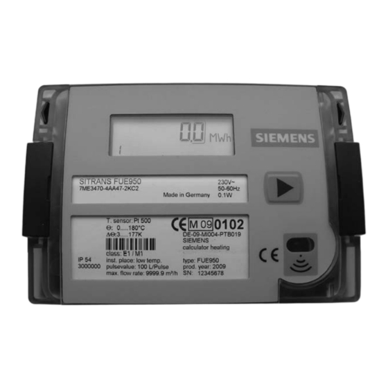
Design Display and push button SITRANS FUE950 has an easy-read 7 digit LCD display with associated pictograms for various functions. As display has been designed for several applications, figures/symbols not used for normal district heating applications will appear in display. - Page 16 Type label A typical FUE950 type label shows the following main information: ● Product name and order number (SITRANS FUE950, 7ME3470-4AA47-2KC2) ● Temperature sensor type and ranges (Pt 500, 0 ...180 °C, ΔT 3 ...177 K) ● Flowmeter installation place (low temp.) ●...
-
Page 17: Installing/Mounting
3. Device installation, see Installation of device (Page 17). Ambient conditions Specifications SITRANS FUE950 energy calculator suitable for indoor and outdoor installations. ● Temperature specifications: – Ambient temperature: 0 ... +55 ºC (+32 ... +131 ºF) – Storage: –25 °C ... +70 °C (-13 ... +158 °F) ●... -
Page 18: Application Settings
SITRANS FUE380). Check both type plates for settings. ● Pt sensor type. Observe information of temperature sensor installation. ● Max. flow rate. Max. flow rate for energy calculator must not be exceeded. SITRANS FUE950 Operating Instructions, 01/2010, SFIDK.PS.022.F4.02... -
Page 19: Installation Of Device
Typically, integrator is mounted on a wall or in a panel. The integrator should be installed in a position that makes operation and service easy. Wall mounting The device is mounted using the wall bracket supplied (ambient temperature: max. 55°C (131°F)). Figure 4-1 Wall mounting of device SITRANS FUE950 Operating Instructions, 01/2010, SFIDK.PS.022.F4.02... - Page 20 Fix sensors in pockets using the screws and make a user sealing for each sensor at the pockets Figure 4-3 Sealing of temperature sensor at pocket SITRANS FUE950 Operating Instructions, 01/2010, SFIDK.PS.022.F4.02...
- Page 21 Flowmeter must be mounted in accordance with the instructions given in the relevant flowmeter operating instructions. Install flowmeter in application as stated on the type label of the energy calculator, i.e. in cold line (low temperature) or hot line (high temperature). SITRANS FUE950 Operating Instructions, 01/2010, SFIDK.PS.022.F4.02...
- Page 22 Installing/Mounting 4.4 Installation of device SITRANS FUE950 Operating Instructions, 01/2010, SFIDK.PS.022.F4.02...
-
Page 23: Connecting
Making cable entries Make a circular hole by dismounting rubber grommet using a flat plier. Note Only use flat pliers as tool Only make the number of cable entries corresponding to the number of cables SITRANS FUE950 Operating Instructions, 01/2010, SFIDK.PS.022.F4.02... - Page 24 (pipe) by heating low temperature Calculator combined Forward "hot line" By heating: cooling/heating, flowmeter in (F) forward "hot line", Blue Return "cold line" forward line (pipe) by heating high temperature Table of type connection for installation SITRANS FUE950 Operating Instructions, 01/2010, SFIDK.PS.022.F4.02...
- Page 25 Pulse input (IN0) of FUE950 must be connected to pulse output external flow meter. The display menu name is IN0, see menu description (Page 39). The pulse input has three terminals, +9, 10 and -11. Only terminals 10 and 11 will be connected to the Siemens flowmeters.
-
Page 26: Sitrans Fue380 And Fus380
For connection of flowmeter, see flowmeter operating instructions. SITRANS F M MAG 5000/6000 When MAG 5000/6000 and SITRANS FUE950 are connected as a heat meter, 2 resistors are required to obtain a correct transmission of pulses. The 2 resistors must be mounted between terminals 57 and 58 in the MAG terminal socket. - Page 27 Connecting 5.2 SITRANS F M MAG 5000/6000 MAG 5000/6000 FUE950 Note Use shielded cable. Connect shield to grounding at flowmeter. For connection of flowmeter, see flowmeter operating instructions. SITRANS FUE950 Operating Instructions, 01/2010, SFIDK.PS.022.F4.02...
-
Page 28: Power Supply Options
If no mains supply is connected, a back-up battery in the mains unit provides the power supply. The date and time remain actual but none of the measuring functions work, incl. flow rate measurement. Figure 5-3 Mains power supply modules, 230 V AC or 24 V AC versions SITRANS FUE950 Operating Instructions, 01/2010, SFIDK.PS.022.F4.02... - Page 29 230 V AC / 24 V AC module Instead of a battery the power can be supplied from a 230 V AC or a 24 V AC power supply module (depending on ordering). Check cable plug connection of power supply module. SITRANS FUE950 Operating Instructions, 01/2010, SFIDK.PS.022.F4.02...
- Page 30 The display is also switched off, but can be switched on again by pressing any button. Communication is retained, e.g. over the M-Bus or the optical interface. WARNING Never connect between two phases, as this will destroy the mains unit SITRANS FUE950 Operating Instructions, 01/2010, SFIDK.PS.022.F4.02...
-
Page 31: Add-On Output And Input Modules
"active" when installed. The settings and functions for the modules can be changed via a free using software tool and the IrDA interface of the FUE950. For more details, please contact Siemens Flow Instruments. The two slots for extension modules are shown in figures below. Slot 1 (to the left) is intended for the M-Bus or RS-232 communication modules or the pulse input module. - Page 32 The functions and settings of the outputs can be freely programmed using a software tool and the IrDA interface, e.g. default settings for pulse values can be changed with the factors 0.1, 1, 10 and 100. SITRANS FUE950 Operating Instructions, 01/2010, SFIDK.PS.022.F4.02...
- Page 33 M-Bus-repeater or M-Bus-master). A number of heat meters can be connected to a control centre. The board contains 2 terminals marked as 24 and 25, which are typically connected to the M-Bus master (M-Bus controlling centre). Figure 5-6 M-Bus module SITRANS FUE950 Operating Instructions, 01/2010, SFIDK.PS.022.F4.02...
- Page 34 M-Bus communication setup Default settings for M-Bus communication can be changed by using a software tool, pc and IrDA adapter. M-Bus communication description is available on request, please contact Siemens. For setup of M-Bus communication, please use HYDRO-SET software tool ®...
- Page 35 1. Remove user sealing (if present) from integrator housing and open lid. 2. Install communication modules (M-Bus, RS-232) in slot 1 (S1). 3. Carefully slide plug onto board. 4. Place module over upper locating stud SITRANS FUE950 Operating Instructions, 01/2010, SFIDK.PS.022.F4.02...
- Page 36 7. Close lid and check meter for correct operation by pressing push button. Renew label seal of housing lid if meter functions correctly. 8. Functions and settings can be checked via display menu 3 and freely programmed using a software tool and the IrDA interface. SITRANS FUE950 Operating Instructions, 01/2010, SFIDK.PS.022.F4.02...
- Page 37 M-Bus or RS-232 module is not used, pulse input module can also be installed in slot 1. 2. Carefully slide plug onto board. 3. Place module over the upper locating stud SITRANS FUE950 Operating Instructions, 01/2010, SFIDK.PS.022.F4.02...
- Page 38 6. Close lid and check meter for correct operation by pressing push button. Renew label seal of housing lid if meter functions correctly. 7. Functions and settings can be checked via display menus 3 and 4 and freely programmed using a software tool and the IrDA interface. SITRANS FUE950 Operating Instructions, 01/2010, SFIDK.PS.022.F4.02...
-
Page 39: Operation (Hardware)
Sensors in forward and return lines must fit right to bottom of sensor pockets. Measurement repeatability stated by manufacturer will be obtained if further described environmental conditions are present. In case of deviating environmental conditions, energy meter has to be remounted regularly for service. SITRANS FUE950 Operating Instructions, 01/2010, SFIDK.PS.022.F4.02... -
Page 40: Display
LCD off to save power and returns to basic display menu when button is pressed again. ● Basic menu loop is number 1 showing the main information (energy, volume, flow, power, temperatures, status information). SITRANS FUE950 Operating Instructions, 01/2010, SFIDK.PS.022.F4.02... -
Page 41: Menu Structure
5. Tariff loop (only visible if activated) 6. Month loop Display menu loops The various loops will show the following information: ("OFF" means display menu is only visible if activated with SW tool, freely changeable) SITRANS FUE950 Operating Instructions, 01/2010, SFIDK.PS.022.F4.02... - Page 42 Tariff energy 2 1.13 (OFF) "In 1" Pulse input counter 1 1.14 (OFF) "In 2" Pulse input counter 2 Sequence Window 1 Window 2 Short press Short press Short press Short press 2 sec. Short press SITRANS FUE950 Operating Instructions, 01/2010, SFIDK.PS.022.F4.02...
- Page 43 Operation (hardware) 6.3 Menu structure Sequence Window 1 Window 2 Short press Short press Short press 1.10 Short press Returns to menu 1.1 SITRANS FUE950 Operating Instructions, 01/2010, SFIDK.PS.022.F4.02...
- Page 44 4 sec. Short press 2 sec. 4 sec. Short press 2 sec. Short press 2 sec. 4 sec. Short press 2 sec. 4 sec. Short press 2 sec. Short press Returns to menu 2.1 SITRANS FUE950 Operating Instructions, 01/2010, SFIDK.PS.022.F4.02...
- Page 45 3.14 Battery remaining day lifetime 3.15 Pulse input flow sensor (text with unit) Sequence Window 1 Window 2 Short press 2 sec. Short press 2 sec. Short press Short press 4 sec. Short press SITRANS FUE950 Operating Instructions, 01/2010, SFIDK.PS.022.F4.02...
- Page 46 Operation (hardware) 6.3 Menu structure 4 sec. Short press Short press Short press 2 sec. Short press 3.10 2 sec. Short press Returns to menu 3.1 SITRANS FUE950 Operating Instructions, 01/2010, SFIDK.PS.022.F4.02...
- Page 47 Accounting date 2 previous "In2" Acc. date 2 previous year year Pulse value 2 Menu Window 1 Window 2 Window 3 2 sec. 4 sec. Short press 2 sec. 4 sec. Short press Returns to menu 4.1 SITRANS FUE950 Operating Instructions, 01/2010, SFIDK.PS.022.F4.02...
- Page 48 In 1 Pulse 1 In 2 Pulse 2 counter counter 6.24 Month - Energy Tariff Tariff Volume Max. Max. In 1 Pulse 1 In 2 Pulse 2 energy energy flow power counter counter rate SITRANS FUE950 Operating Instructions, 01/2010, SFIDK.PS.022.F4.02...
-
Page 49: Function Test
(forward or return). 3. Value of flowmeter pulse output is the same as value of energy meter pulse input. 4. Expected flow rate is within measuring range of SITRANS FUE950 calculator. 5. Temperature sensors are of the same pair. - Page 50 Operation (hardware) 6.4 Function test SITRANS FUE950 Operating Instructions, 01/2010, SFIDK.PS.022.F4.02...
-
Page 51: Service And Maintenance
The SITRANS FUE950 battery can easily be replaced, please refer to chapter Power supply options (Page 26) for detailed instructions. Sealing The individual parts of the SITRANS FUE950 system are to be sealed in accordance with local provisions in the country in which it is installed. SITRANS FUE950... - Page 52 2. Energy calculator is provided with a thread seal or adhesive label seal. Figure 7-2 S - User sealing 3. Sensors are thread-sealed. Note Important It is important that sealing threads are kept as short as possible and are tensioned well to seal. SITRANS FUE950 Operating Instructions, 01/2010, SFIDK.PS.022.F4.02...
-
Page 53: Technical Support
Service and maintenance 7.3 Technical support Technical support CAUTION Repair and service must be carried out by approved Siemens Flow Instruments personnel only. Note Siemens Flow Instrument defines sensors as non-repairable products. Technical Support If you have any technical questions about the device described in these Operating Instructions and do not find the right answers, you can contact Technical Support: ●... -
Page 54: Return Procedures
Waste industrial batteries are accepted back by Siemens or by the local Siemens representative. Please talk to your local Siemens contact or follow the return procedures of Siemens Flow Instruments described in chapter: Return procedures (Page 52) SITRANS FUE950 Operating Instructions, 01/2010, SFIDK.PS.022.F4.02... -
Page 55: Troubleshooting/Faqs
– "-" (if communication is working properly) – "5" (if communication is impossible) 7. Shows: – "-" (if there is no power failure) – "8" or "9" (if mains power or battery power, respectively, is insufficient) SITRANS FUE950 Operating Instructions, 01/2010, SFIDK.PS.022.F4.02... - Page 56 E - 9 Display Battery empty (checked Monitors: Replace battery. switched off every day). remaining usage time displayed Shows: permanently error if remaining time < 400 days Disables: no functions SITRANS FUE950 Operating Instructions, 01/2010, SFIDK.PS.022.F4.02...
- Page 57 SW-tool Leak detection water meter at Disables: Error is used as a warning. In2, check by end of day no functions Remedy depends on settings by local user programming via SW-tool SITRANS FUE950 Operating Instructions, 01/2010, SFIDK.PS.022.F4.02...
- Page 58 Troubleshooting/FAQs 8.1 Error information and codes SITRANS FUE950 Operating Instructions, 01/2010, SFIDK.PS.022.F4.02...
-
Page 59: Technical Data
EN1434, connection via separate IrDA-adapter Rated operation Enclosure IP54 in accordance with IEC 529 conditions Material PC Lexan 141R Transparent 111 • Pipe/wall fitting PA 6,6 GF25 • Other plastic parts ABS Cycolac GPM500 • SITRANS FUE950 Operating Instructions, 01/2010, SFIDK.PS.022.F4.02... - Page 60 Pulse output module, 2 outputs (Out1, Out2) Combination module of 2 inputs (In1, In2) and 1 output (Out1) Communication modules M-Bus or RS 232 Pulse output Type Passive "open collector" pulse output, outputs potential isolated to each other SITRANS FUE950 Operating Instructions, 01/2010, SFIDK.PS.022.F4.02...
- Page 61 RS 232 output Type The optional plug-in RS232 communication module is a serial interface and permits data exchange with the calculator. For this purpose a special data cable is necessary Protocol M-Bus according EN1434 SITRANS FUE950 Operating Instructions, 01/2010, SFIDK.PS.022.F4.02...
- Page 62 50/60 Hz (incl. battery backup) 24 V AC module Plug-in module for 24 V AC (incl. battery backup) Battery backup Only with mains supply modules by internal 3.0 V lithium battery (type BR 2732) SITRANS FUE950 Operating Instructions, 01/2010, SFIDK.PS.022.F4.02...
-
Page 63: Dimension Drawings
Dimension drawings 10.1 Dimensional drawings FUE950 energy meter Figure 10-1 FUE950, dimensions in mm (in) Figure 10-2 Panel mounting, dimensions in mm (in) SITRANS FUE950 Operating Instructions, 01/2010, SFIDK.PS.022.F4.02... -
Page 64: Temperature Sensor
Dimension drawings 10.1 Dimensional drawings Temperature sensor Figure 10-3 Pt500 temperature sensor, dimensions in mm (in) Figure 10-4 Sensor pocket (stainless steel), dimensions in mm (in) Figure 10-5 Sensor pocket (brass), dimensions in mm (in) SITRANS FUE950 Operating Instructions, 01/2010, SFIDK.PS.022.F4.02... -
Page 65: Spare Parts/Accessories
Spare parts/Accessories 11.1 Ordering In order to ensure that the ordering data you are using is not outdated, the latest ordering data is always available on the Internet: Catalog process instrumentation (http://www.siemens.com/processinstrumentation/catalogs) 11.2 Accessories Option modules Description Pulse input module... -
Page 66: Power Supply
Description Data RS 232 module Data RS 232 module incl. serial data cable (1.5 m incl. serial PC plug) M-Bus slave module 11.3 Power supply Description 3.0 V C-cell battery 3.6 V D-cell battery SITRANS FUE950 Operating Instructions, 01/2010, SFIDK.PS.022.F4.02... -
Page 67: Temperature Sensor Pocket
Stainless steel pocket 6 mm, G½B x 210 mm (PN 25) 11.5 Pt500 temperature sensor pair Description Pt500 temperature sensor, 2-wire, with MID/EN approval and verification Cable length: 2 m, 3 m, 5 m, 10 m SITRANS FUE950 Operating Instructions, 01/2010, SFIDK.PS.022.F4.02... - Page 68 Spare parts/Accessories 11.5 Pt500 temperature sensor pair SITRANS FUE950 Operating Instructions, 01/2010, SFIDK.PS.022.F4.02...
-
Page 69: Appendix
Appendix Conformity to guidelines Declaration of conformity Siemens hereby declares that this product meets the essential requirements of the following guidelines: ● EMC – Directive (2004/108/EC) ● R&TTE – Directive (1999/5/EC) ● MID – Directive (2004/22/EC) ● Council Directive (2006/95/EC) ●... - Page 70 Appendix A.2 Certificates SITRANS FUE950 Operating Instructions, 01/2010, SFIDK.PS.022.F4.02...
-
Page 71: Index
Hotline, 51 Internet Contact person, 6, 51 Flowdocumentation, 6 Support, 51 Introduction, 5 IrDA interface, 29, 30 Items supplied, 5 Laws and directives, 7 Lithium batteries Return, 52 Safety, 8 Loop, 39 Material compatibility, 7 SITRANS FUE950 Operating Instructions, 01/2010, SFIDK.PS.022.F4.02... - Page 72 Further information www.siemens.com/flow Siemens Flow Instruments A/S Subject to change without prior notice A5E02518958-01 Nordborgvej 81 Order No.:A5E02518958-01 DK-6430 Nordborg Lit. No.: SFIDK.PS.022.F4.02 © Siemens AG 01.2010 All rights reserved www.siemens.com/processautomation...