Table of Contents
Quick Links
See also:
Installation Manual
Instruction Manual
Form 5007
August 2008
133 Series Self-Operated Regulators
W1327
TYPES 133H, 133L, anD 133Z REgULaTORS
Introduction
WaRnIng
!
Installation, operation and maintenance
procedures performed by unqualified
personnel may result in improper
adjustment and unsafe operation. Either
condition may result in equipment
damage or personnel injury. Use qualified
personnel when installing, operating and
maintaining the 133 Series regulators.
If a leak develops in the system, the
escaping gas may accumulate and
become a fire or explosion hazard.
Immediately call qualified service
personnel in case of trouble.
Scope of Manual
This manual provides specifications, instructions
for installation, adjustment, maintenance, and parts
information for the 133 Series.
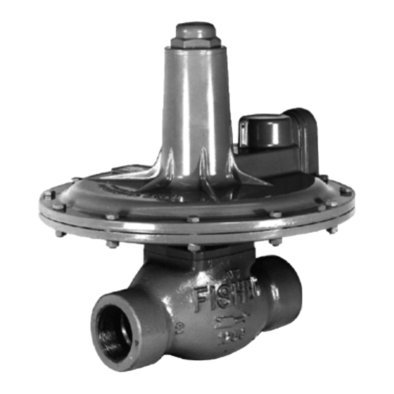
Figure 1. 133 Series Gas Regulators
Only personnel qualified through training or experience
should install, operate and maintain this regulator. If
there are any questions concerning these instructions,
contact your local Sales Office before proceeding.
Description
The 133 Series self-operated gas regulators, shown
in Figure 1 are primarily designed for industrial and
commercial applications supplying gas to furnaces,
burners and other appliances. The 133 Series
balancing system enables the regulator to provide
accurate control gas pressure for maximum combustion
efficiency despite varying inlet pressure conditions. The
single port construction provides bubble tight shutoff.
An external downstream control line is required for
the operation of the regulator. A restriction collar is
available to reduce the flow capacity of the regulator.
www.emersonprocess.com/regulators
133 Series
W6803
TYPE 133HP REgULaTOR
Table of Contents

Related Manuals for Emerson Fisher 133H


Summary of Contents for Emerson Fisher 133H
- Page 1 133 Series Instruction Manual Form 5007 August 2008 133 Series Self-Operated Regulators W1327 W6803 TYPE 133HP REgULaTOR TYPES 133H, 133L, anD 133Z REgULaTORS Figure 1. 133 Series Gas Regulators Introduction WaRnIng Only personnel qualified through training or experience Installation, operation and maintenance should install, operate and maintain this regulator.
-
Page 2: Specifications
133 Series Specifications End Connections adjusting Screw: Steel 2-inch Cast iron NPT (internal), cast iron Optional Restriction Collar: Aluminum CL125 FF flanged, steel NPT (internal). or steel Temperature Capabilities CL150 RF flanged -20° to 150°F (-29° to 66°C) Outlet Pressure Ranges Control Line Connection See Table 1 Types 133H, 133L, and 133Z: 3/4-inch NPT... -
Page 3: Principle Operation
133 Series INLET PRESSURE OUTLET PRESSURE ATMOSPHERIC PRESSURE BOOST PRESSURE INLET PRESSURE InLET PRESSURE OUTLET PRESSURE OUTLET PRESSURE ATMOSPHERIC PRESSURE aTMOSPHERIC PRESSURE BOOST PRESSURE BOOST PRESSURE A6555 Figure 2. Operational Schematic of Type 133L Regulator (Also Typical of Type 133H) Principle Operation downstream pressure is registered on the bottom Refer to the operational schematics in Figures 2 and 3. -
Page 4: Installation
Type 133HP 133 Series overpressure protection is needed if the actual inlet pressure exceeds the outlet pressure rating. Type 133HP Maximum operating inlet pressure for the 133 Series regulators is given in Table 2. All models must be protected against inlet pressure above their listed maximum. - Page 5 133 Series Table 1. 133 Series Outlet Pressure Ranges, Control Springs OUTLET PRESSURE RangE COnTROL SPRIngS TYPE Color Code Free Length, Wire Diameter, Inches w.c./Psig bar/mbar Part number Stripe Inch (mm) Inch (mm) 1.5 to 3 psig 0,10 to 0,21 bar 1H975927032 Orange 7-3/8 (187)
-
Page 6: Maintenance
133 Series adjustment To increase the pressure setting, remove the closing cap (key 9; Figures 10, 11, 12, and 14) and turn the adjusting screw (key 11) clockwise; to lower the setting, turn the adjusting screw counterclockwise. A pressure gauge should always be used when adjustments are being made. - Page 7 133 Series W1371/IL W1372/IL Figure 5. Inspecting Guide Bushing and Stem Seal O-Ring Figure 6. Installing Balancing Diaphragm. The Side of Diaphragm Marked Piston Side Must Face Casing. 4. Insert a 1/2-inch (12,7 mm) open-end wrench 8. Unscrew the cap screws and nuts (keys 35 and 36) between the legs of the cage (key 5) and place and remove the spring case.
- Page 8 133 Series and the lower casing (key 7) until the diaphragm fits 2. Unscrew the four locknuts (key 34) and lift the smoothly over the diaphragm plate without wrinkles actuator portion off the body (key 1). All of the trim and the bead fits snugly and evenly in the groove parts will come out of the body with the actuator.
- Page 9 133 Series PROTECT THE O-RIng SURFaCE 3/4-InCH FROM DaMagE (19,05 mm) STEM HEx A7007 Figure 7. Stem and Diaphragm Assembly 7. Remove the six cap screws (key 62) from the spring 1. With the Type 133HP completely disassembled, case (key 8). Lift off the spring case, upper spring start the reassembly by applying Magnalube-G seat (key 41) and spring (key 12).
- Page 10 133 Series aPPLY PTFE SEaLanT TO THREaDS anD InSTaLL WITH COnTROL LInE COnnECTIOn POInTIng aWaY FROM THE CaSIng aDaPTOR 1/4-InCH nPT COnTROL LInE COnnECTIOn A7008/IL Figure 8. Lower Casing and Casing Adaptor Assembly WHEn aSSEMBLIng THE aCTUaTOR, THE UPPER CaSIng anD aDaPTER SHOULD BE POSITIOnED SO THaT TWO HOLES In THE 5-1/4-InCH (133 mm) BOLT HOLE CIRCLE aRE EQUaLLY SPaCED OVER THE...
-
Page 11: Parts Ordering
133 Series 6. Assemble the upper and lower casings, noting 12. Install the valve disk (key 28), registration disk that two of the holes in the 5-1/4-inch (133 mm) (key 29), washer (key 30) and hex nut (key 31) diameter bolt circle in the mounting plate adaptor onto the stem. - Page 12 133 Series 40A3066 DC - DOW CORnIng nO.3 nS - nEVER-SEEZ Figure 10. Type 133L Assembly Description Part number Description Part number Cage, aluminum (including roll pins, key 5A) 20A3048X012 10* Closing Cap Gasket, neoprene (CR) Bearing, nylon (PA) 10A3049X012 Types 133H, 133L, and 133Z 1N446206992 Lower Casing...
- Page 13 133 Series 40A3070 DC - DOW CORnIng nO.3 nS - nEVER-SEEZ Figure 11. Type 133H Assembly Description Part number Description Part number Spring, steel (continued) Spring, steel (continued) 5 to 9-inches w.c. (12,00 to 22,00 mbar) Blue 10C1241X012 Black 1D892727012 36 to 50 psig (2,48 to 3,45 bar) 8.5 to 18-inches w.c.
- Page 14 133 Series 40A3071 DC - DOW CORnIng nO.3 nS - nEVER-SEEZ Figure 12. Type 133Z Assembly Figure 13. Optional Restriction Collar Assembly...
- Page 15 133 Series A7010/IL A7011/IL Figure 14. Type 133HP Actuator Assembly...
- Page 16 For further information visit www.emersonprocess.com/regulators The Emerson logo is a trademark and service mark of Emerson Electric Co. All other marks are the property of their prospective owners. Fisher is a mark owned by Fisher Controls, Inc., a business of Emerson Process Management.