
Summary of Contents for GE Druck PV 622
- Page 1 Sensing & Inspection Technologies Druck PV 62x pneumatic/hydraulic pressure stations user manual - K0457...
- Page 2 Issue 1 Quick reference data A1.1 PV 621: Pneumatic pressure station -950 mbar to 20 bar (-13.5 to 300 psi) PV 622: Pneumatic pressure station -950 mbar to 100 bar (-13.5 to 1500 psi) PV 623: Hydraulic pressure station 0 to 1000 bar (0 to 15000 psi) A1.2 PV 62x + DPI 620 + PM 620 Recommended pressure modules (PM 620) *...
-
Page 3: Safety
Issue 1 Safety Before you use the instrument, make sure that you read and understand all the related data. This includes: the applicable local safety procedures, this publication, and the instructions for the accessories/options/equipment you are using it with. General warnings WARNING •... - Page 4 Issue 1 • To prevent an explosion or fire, use only the GE specified battery, power supply and battery charger. • To make sure the display shows the correct data, disconnect the test leads before you set the power to on or change to another measure or source function.
-
Page 5: Overview
Issue 1 Overview There are three pressure stations in the PV 62x series: PV 621 • two pneumatic pressure stations to give you accurate and controlled pressure and vacuum conditions: PV 621: -950 mbar to 20 bar (-13.5 to 300 psi) version PV 622: -950 mbar to 100 bar (-13.5 to 1500 psi) version PV 622 •... -
Page 6: Summary Of Functions
Issue 1 Summary of This table gives a summary of the available functions with the PV 62x pressure stations. functions PV 62x - pressure station functions Function Pneumatic pressure stations PV 621 PV 621: Pressure from vacuum (95%) to 20 bar (300 psi); * PV 622: Pressure from vacuum (95%) to 100 bar (1500 psi) PV 622 Selector switch to change the pump operation from pressure... -
Page 7: About This Manual
Issue 1 About this manual This user manual is set up for you to use on a computer or similar device that has the necessary software to read a Portable Document Format (PDF) file. It is supplied as a PDF on a compact disc (CD) but you can copy or save the PDF onto a computer or similar device that has the necessary PDF software. - Page 8 Issue 1 viii About this manual K0457 - [EN] English...
-
Page 9: Table Of Contents
Issue 1 Table of Contents Quick reference data ............ii Safety. - Page 10 Issue 1 Chapter 2: Pneumatic pressure operation (PV 621) 2.1 Introduction ............2-1 2.2 Release the pressure.
- Page 11 Issue 1 4.7 Drain all the hydraulic fluid..........4-6 4.7.1 Preparation .
- Page 12 Issue 1 xi Table of Contents K0457 - [EN] English...
-
Page 13: Chapter 1: Instrument Parts, Accessories And Options
Chapter 1: Instrument parts, accessories and options 1.1 Introduction This chapter gives a description of the different parts of each instrument and the accessories/options available. 1.2 PV 621 models 1. Optional accessory: Pressure connection for a pressure relief valve (PRV); see Section 1.2.1. A blanking plug is standard. -
Page 14: Pressure Relief Valve (Prv)
Issue 1 1.2.1 Pressure relief valve (PRV) To give your attached devices overpressure protection (device under test, PM 620 module), we recommend you use one of our range of optional pneumatic PRVs; see Section 1.5 (Accessories). To attach or adjust a PRV, see Section 2.4. 1.2.2 Test port To attach the device under test, the test port uses “Quick fit”... -
Page 15: Selector (Pressure/Vacuum)
Issue 1 1.2.5 Selector (pressure/vacuum) Caution: Before you turn the pressure/vacuum selector to + or -, release all the pressure. Sudden high pressure in the pump mechanism can cause damage. This control sets the operation of the instrument (pressure or vacuum). -
Page 16: Pv 622 Models
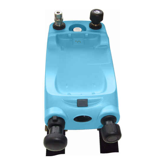
Issue 1 1.3 PV 622 models 1. Optional accessory: Pressure connection for a pressure relief valve (PRV); see Section 1.3.1. A blanking plug is standard. 2. Test port: Pressure connection (G1/8 or 1/8NPT) to attach the device under test; see Section 1.3.2. 3. -
Page 17: Test Port
Issue 1 1.3.2 Test port To attach the device under test, the test port uses “Quick fit” pressure adaptors; see Section 1.5 (Accessories). These are easy to remove, change and install; see Section 3.3 (Attach/Remove the device under test). 1.3.3 Pneumatic pressure release valve This is a needle point valve that lets you release the pressure or vacuum, or seal the system. - Page 18 Issue 1 Full control When the refill valve is open, you have full control to increase or decrease the pressure/vacuum. Before you seal the system (Section 1.3.3), turn the wheel to the necessary position: • for equal adjustment, turn it to the middle of its range •...
-
Page 19: Selector (Pressure/Vacuum)
Issue 1 1.3.6 Selector (pressure/vacuum) Caution: Before you turn the pressure/vacuum selector to + or -, release all the pressure. Sudden high pressure in the pump mechanism can cause damage. This control sets the operation of the instrument (pressure or vacuum). -
Page 20: Pv 623 Models
Issue 1 1.4 PV 623 models 1. Optional accessory: Pressure connection for a pressure relief valve (PRV); see Section 1.4.1. A blanking plug is standard. 2. Test port: Pressure connection (G1/8 or 1/8NPT) to attach the device under test; see Section 1.4.2. 3. -
Page 21: Test Port
Issue 1 1.4.2 Test port To attach the device under test, the test port uses “Quick fit” pressure adaptors; see Section 1.5 (Accessories). These are easy to remove, change and install; see Section 4.4 (Attach/Remove the device under test). 1.4.3 Hydraulic pressure release valve/reservoir access This valve lets you release the pressure or seal the system. -
Page 22: Volume Adjuster Wheel
Issue 1 1.4.5 Volume adjuster wheel The refill valve (Section 1.4.4) sets the operation of the Volume adjuster wheel: Full control or refill Full control When the refill valve is open, you have full control to increase or decrease the pressure. At higher pressures, it is easier to turn the wheel if you fold in the handle: 1. -
Page 23: Accessories
Issue 1 1.5 Accessories 1. “Quick fit” pressure adaptors (G1/8 and 1/8NPT); easy to remove, change and install 2. Carrying strap with a shoulder strap and a carry handle 3. PV 623 models only: Refill bottle for hydraulic fluid 4. Safety and quick reference guide 5. - Page 24 Issue 1 10. Hydraulic PRVs to give attached devices overpressure protection; see Table 1-2. Table 1-2: Recommended PRVs (Hydraulic) PRV P/N Recommended Factory setting Adjustable range for: IO620-PRV-H1 10 to 50 145 to 725 IO620-PRV-H2 3000 50 to 200 725 to 2900 IO620-PRV-H3 PV 623 only 6000...
-
Page 25: Chapter 2: Pneumatic Pressure Operation (Pv 621)
Chapter 2: Pneumatic pressure operation (PV 621) 2.1 Introduction Chapter 1 gives a description of the different parts of the instrument: This chapter gives examples of how to connect and use the PV 621 pressure station to give the necessary pressure or vacuum conditions. -
Page 26: Procedure (To Attach)
Issue 1 2.3.1 Procedure (to attach) b. (G) / BSPP c. (G) / BSPP P ≤ 100 bar Step Procedure Step Procedure Remove the adaptor Attach the adaptor to the device; if necessary use one of the alternative Use an applicable seal for the pressure adaptors in Section 1.5 (Accessories), connection: then tighten to the applicable torque. -
Page 27: Procedure (To Attach)
Issue 1 2.4.1 Procedure (to 1. Steps (a) and (b): Remove the blanking plug or, if applicable, attach) the PRV you are using. Note: Before you put it into storage, make sure it is clean and dry. 2. Steps (c) and (d): Choose a clean, dry PRV with the correct pressure value for the devices you are using and tighten it into position (hand tight only). -
Page 28: Vacuum Procedure
Issue 1 2.5.1 Vacuum procedure Step Procedure (Vacuum) Set the pressure/vacuum selector to vacuum (-); fully counterclockwise. To do equal adjustments (up or down) at the end of the procedure, turn the volume adjuster to the middle of its range of operation. To get the maximum vacuum, turn the volume adjuster fully clockwise. -
Page 29: Chapter 3: Pneumatic Pressure Operation (Pv 622)
Chapter 3: Pneumatic pressure operation (PV 622) 3.1 Introduction Chapter 1 gives a description of the different parts of the instrument: This chapter gives examples of how to connect and use the PV 622 pressure station to give the necessary pressure or vacuum conditions. -
Page 30: Procedure (To Attach)
Issue 1 3.3.1 Procedure (to attach) b. (G) / BSPP c. (G) / BSPP P ≤ 100 bar Step Procedure Step Procedure Remove the adaptor Attach the adaptor to the device; if necessary use one of the alternative Use an applicable seal for the pressure adaptors in Section 1.5 (Accessories), connection: then tighten to the applicable torque. -
Page 31: Procedure (To Attach)
Issue 1 3.4.1 Procedure (to 1. Steps (a) and (b): Remove the blanking plug or, if applicable, attach) the PRV you are using. Note: Before you put it into storage, make sure it is clean and dry. 2. Steps (c) and (d): Choose a clean, dry PRV with the correct pressure value for the devices you are using and tighten it into position (hand tight only). -
Page 32: Vacuum Procedure
Issue 1 3.5.1 Vacuum procedure Step Procedure (Vacuum) Set the pressure/vacuum selector to vacuum (-); fully counterclockwise. Open the refill valve (1 turn). To do equal adjustments (up or down) at the end of the procedure, turn the volume adjuster wheel to the middle of its range of operation. -
Page 33: Chapter 4: Hydraulic Pressure Operation (Pv 623)
Chapter 4: Hydraulic pressure operation (PV 623) 4.1 Introduction Chapter 1 gives a description of the different parts of the instrument: This chapter gives examples of how to connect and use the PV 623 pressure station to give the necessary hydraulic pressure conditions. -
Page 34: Release The Pressure
Issue 1 4.3 Release the To release all the pressure in this instrument: pressure Step Procedure Open the refill valve counterclockwise (1 turn). Open the pressure release valve counterclockwise (1 turn). To control a change in pressure conditions (for example, to go to or through another test pressure) use the volume adjuster wheel (Section 1.4.5). -
Page 35: Procedure (To Remove)
Issue 1 4.4.2 Procedure To remove a device, release the pressure first (Section 4.3). (to remove) You can then do steps 4, 3, and 1 in Section 4.4.1 but do the operations in the opposite direction. 4.5 Attach/Adjust a WARNING: Pressurized gases and fluids are dangerous. Before you attach or disconnect pressure equipment, safely release all the pressure. -
Page 36: Hydraulic Pressure Procedure
Issue 1 2. Remove the plastic cap from the end of the PRV. 3. Set the necessary pressure with the pressure station (see Section 4.6.1). 4. When the pressure in the pressure station is at the new PRV pressure, turn the adjustment screw until the PRV operates: counterclockwise decreases the operating pressure clockwise increases the operating pressure 5. -
Page 37: Add More Hydraulic Fluid
Issue 1 4.6.2 Add more hydraulic fluid If the device under test has a large fluid capacity, you can add hydraulic fluid during the pressure procedure. Step Procedure To seal off all the pressure in the test port and the pressure module connection, close the refill valve. -
Page 38: Drain All The Hydraulic Fluid
Issue 1 4.7 Drain all the In some conditions, it is necessary to fully drain the hydraulic fluid from your PV 62x pressure station; for example: hydraulic fluid • if you are using water and the storage or operating temperature is going to be less than 4°C (39°F) •... -
Page 39: Chapter 5: Pressure Calibrator Operation (Dpi 620)
Chapter 5: Pressure calibrator operation (DPI 620) 5.1 Introduction This section gives examples of how to connect and use the pressure stations to do pressure calibrations with the DPI 620 calibrator and the applicable pressure modules (PM 620). Before you start: •... -
Page 40: Pm 620 Module Parts
Issue 1 5.2.2 PM 620 module Caution: To prevent damage to the PM 620 module, only parts use it within the specified pressure limit on the label. Pressure module (PM 620) with a pressure connection, reference port (a) and a label. The label includes: Pressure range. -
Page 41: Measure Pressure/Vacuum
Issue 1 5.3 Measure When the pressure calibrator assembly is complete (Section 5.2), use the calibrator to measure the pressure or, if pressure/vacuum applicable, the vacuum in the pressure station; for example: to calibrate a gauge or indicator. 5.3.1 Procedure overview To use the pressure calibrator, complete these procedures: •... -
Page 42: Dpi 620 Calibrator: Set The Pressure Function
Issue 1 • If necessary, change the Automation options for the CH1 and/or CH2 output functions: item This includes: Nudge, Span Check, Percent Step, Defined Step, Ramp; refer to the user manual - K0449 • If necessary, change the Configuration: item This includes: Data Logging, Documenting, and Advanced options;... -
Page 43: Dpi 620 Calibrator: Set The Pressure Units
Issue 1 5.3.3 DPI 620 calibrator: Set the pressure units This example shows the sequence to set the pressure units. It is a similar procedure for other units. Task Settings Channel Settings Select Units Select Units Channel Settings Task Settings 5.3.4 DPI 620 calibrator: Set up a Leak Test To do a leak test, set the Utility to Leak Test and then set the... -
Page 44: Dpi 620 Calibrator: Set The Pm 620 Module To Zero
Issue 1 (2) Set the Leak Test When you have set the Utility to Leak Test, you can set these options options: Wait Time: The time before the test starts in hours:minutes:seconds (hh:mm:ss) Test Time: The period of the leak test in hours:minutes:seconds (hh:mm:ss) Note: To set the Leak Test options, you must have a PM 620 module correctly installed (Section 5.2.3). -
Page 45: Example Procedure: Gauge/Indicator Calibration
Issue 1 Select Zero Accept the adjustment value Select Settings TAP the window (Maximise) See the new reading and go back to the Home window. 5.3.6 Example procedure: Gauge/indicator calibration 1. Assemble the pressure calibrator with the correct PM 620 module and PRV (if applicable);... -
Page 46: Example Procedure: Transmitter Calibration
Issue 1 4. To set the necessary pressure or vacuum for the calibration, use the specified procedures for your PV 62x pressure station*. • * Reference PV 621 models: see Chapter 2 (Pneumatic pressure operation (PV 621)) • PV 622 models: see Chapter 3 (Pneumatic pressure operation (PV 622)) •... -
Page 47: Example Procedure: Switch Test
Issue 1 • * Reference PV 621 models: see Chapter 2 (Pneumatic pressure operation (PV 621)) • PV 622 models: see Chapter 3 (Pneumatic pressure operation (PV 622)) • PV 623 models: see Chapter 4 (Hydraulic pressure operation (PV 623)) 4. - Page 48 Issue 1 • * Reference PV 621 models: see Chapter 2 (Pneumatic pressure operation (PV 621)) • PV 622 models: see Chapter 3 (Pneumatic pressure operation (PV 622)) • PV 623 models: see Chapter 4 (Hydraulic pressure operation (PV 623)) 4.
-
Page 49: Chapter 6: Maintenance Procedures
Chapter 6: Maintenance procedures 6.1 Introduction This section gives procedures to maintain the unit in a good condition. Return the instrument to the manufacturer or an approved service agent for all repairs. Do not dispose of this product as household waste. Use an approved organisation that collects and/or recycles waste electrical and electronic equipment. -
Page 50: Procedure
Issue 1 6.4.2 Procedure 1. Seal the test port connection with the blanking plug. 2. Attach the applicable PM 620 module PV 621 models: P/N IPM620-13G (20 bar) PV 622 models: P/N IPM620-165G (100 bar) PV 623 models: P/N IPM620-23A (1000 bar) 3. -
Page 51: Chapter 7: Specification
Chapter 7: Specification 7.1 PV 62x models For a full specification of the PV 62x pressure stations, refer to the datasheet supplied on the CD (CD: P/N UD-0002) Table 7-1: General specification (PV 62x Operating temperature -10 to 50°C (14 to 122°F) PV 623 models only: See Caution * Storage temperature -20 to 70°C (-4 to 158°F) -
Page 52: Pressure Data (Pv 62X Models)
Issue 1 7.1.1 Pressure data (PV 62x models) Table 7-2: Pressure specification (PV 62x) PV 621 PV 622: PV 623: (Pneumatic) (Pneumatic) (Hydraulic) Range -950 mbar to 20 bar -950 mbar to 100 bar 0 to 1000 bar (-13.5 to 300 psi) (-13.5 to 1500 psi) (0 to 15000 psi) Minimum resolution... -
Page 53: Pm 620 Modules
Issue 1 7.2 PM 620 modules For a full specification of the PM 620 module, refer to the datasheet supplied on the CD (CD: P/N UD-0002) Table 7-3: General specification (PM 620 Operating temperature -10 to 50°C (14 to 122°F) Calibrated range: 0 to 50°C (32 to 122°F) Storage temperature -20 to 70°C (-4 to 158°F) - Page 54 Issue 1 7-4 Specification K0457 - [EN] English...
- Page 55 Customer service Visit our web site: www.gesensinginspection.com...