
Related Manuals for GE Druck DPI 610


Summary of Contents for GE Druck DPI 610
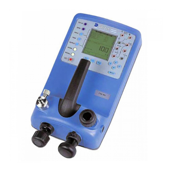
- Page 1 99 Washington Street Melrose, MA 02176 Phone 781-665-1400 Toll Free 1-800-517-8431 Visit us at www.TestEquipmentDepot.com Sensing & Inspection Technologies Druck DPI 610/615 IS Intrinsically Safe Portable Pressure Calibrator User manual - K0430...
- Page 2 WARNING Before operating this intrinsically safe instrument, read the safety instructions and the special conditions stated on the ATEX certificate (Appendix 2) Safety The manufacturer has designed this equipment to be safe when operated using the procedures detailed in this manual. Do not use this equipment for any other purpose than that stated.
- Page 3 K0430 Issue No. 2...
- Page 4 ATEX Approved Models Introduction These instructions detail the requirements for using the DPI 610 IS and DPI 615 IS intrinsically safe pressure calibrator in a hazardous area. Read the whole publication before starting. Markings II 1 G..............Equipment group & category Ex ia IIC T4 Ga..............
- Page 5 Electrical Parameters Maximum Output Parameters at the External Measurement Connectors: lin (SK1) Vin (SK2) SwitchIn (SK3) = 1.1V d.c. = 1.1V d.c. = 1.1V d.c. = 0.16 mA d.c. = 0.11 µA d.c. = 12 mA d.c. = 0.15 mW = 0.03 µW = 11 mW = 0.05 µF...
- Page 6 Specification Safe working pressure 20 bar range (300 psi) 1.75 x full-scale 350 bar range (5000 psi) 1.2 x full-scale 400 bar range (6000 psi) 1.5 x full-scale All other ranges 2 x full-scale Accuracy Combined non-linearity, hysteresis and repeatability ±70 mbar range (2 inHg) 0.05% F.S.
-
Page 7: Table Of Contents
Introduction General Description of Procedures Summary of Functions Using this Guide OPERATOR CONTROLS DISPLAY HARD KEY FUNCTIONS SOFT KEYS CURSOR KEYS ELECTRICAL CONNECTIONS Getting Started Fitting Batteries Switching On Change Pressure Units Voltage and Current Measurement Typical Calibration Set-up (Pressure to Voltage) Zero Display Reading Task Selection Task Key... - Page 8 Advanced Task General Select Input Ambient Temperature Measurement Process Functions Tare Process Function Min/Max Process Function Filter Process Function Flow Function % Span Select Output Electrical Outputs (Loop Power) mA Step mA Ramp mA Value Define New Task Clear Task Memory Operations Saving Display or Data Log Store Operations (Screen Snapshots)
- Page 9 Date and Time (Real Time Clock) Date Format Set Date Set Time Calibration General Calibration Check Calibration Adjustment Guide to Calibration Procedures Test Equipment Using the Calibration Menu Change PIN Calibrate Internal Ranges Internal Pressure Range Voltage Input Range (5 Volts) Voltage Input Range (30 Volts) Current Input Range (55 mA) Current Output Range (24 mA)
-
Page 10: Description Of Procedures
INTRODUCTION Summary of Functions General The DPI 610 IS and DPI 615 IS intrinsically safe instruments measure and display pneumatic and hydraulic pressure applied to the test port. Pressure measurement can be absolute, gauge and sealed gauge and in ranges from 2.5 mbar to 700 bar (1.0 inH to 10000 psi). -
Page 11: Summary Of Functions
INTRODUCTION Summary of Functions Using This Guide The following key symbols are used in the procedure diagrams: Shaded cursor keys indicate that a combination of these four keys, Up, Down, Left and Right should be used to (e.g.) enter an alpha numeric value or to select a function. -
Page 12: Operator Controls
INTRODUCTION Summary of Functions OPERATOR CONTROLS (Figure 1 and 2) These divide into two groups, the operator/display controls (Figure 1) and the pressure/ vacuum generation components (Figure 2). The operator controls and a typical display, common to all instrument versions, is shown below. max 30V DPI 615 IS TASK: BASIC... -
Page 13: Hard Key Functions
INTRODUCTION Summary of Functions HARD KEY FUNCTIONS (Fig. 1) Page Function reference This key selects the instrument ON and OFF. The SETUP key provides access to the instrument’s general SETUP* configuration parameters that are set-up to certain default parameters on delivery. The ZERO key zeroes either the selected input or output display, only if ZERO the display reading is within 5% of zero. -
Page 14: Soft Keys
INTRODUCTION Summary of Functions SOFT KEYS (Fig. 1) Three soft keys, designated F1, EXIT and F2, are situated immediately below the display as shown below. These keys have their function allocated by the instrument software which is indicated in the bottom of the display (Voltage for F1 and Units for F2 in this example). -
Page 15: Electrical Connections
INTRODUCTION Summary of Functions ELECTRICAL CONNECTIONS Cover, closed when not using connectors External transducer RS232 connector Temperature sensor Figure 3 - Electrical System Connections Measurement inputs and Source outputs are made via the control panel sockets as shown below: max 30V DPI 615 IS CAT II TASK: BASIC... -
Page 16: Getting Started
Getting Started Fitting Batteries Manufacturer Type No. Energizer Industrial Type EN93 Energizer Type E93.LR14.C.AM2 Duracell Type MN1400-LR14 Varta No.4014 Type LR14.C.AM2 Procell Industrial Type MN1400-LR14 Cover fixing screws. TASK: BASIC Six alkaline C cells, see table. Only use the battery type in VOLTAGE the table. -
Page 17: Change Pressure Units
Getting Started Change Pressure Units To change the pressure units proceed as follows. If the four units displayed are not the units required, press TASK and select any task, other than BASIC, press SETUP and proceed as detailed on page 36. To return to BASIC mode, press TASK and select BASIC. In BASIC mode, the unit is configured to carry out basic Pressure to Voltage (P to V) or Pressure to Current (P to I) tests, a typical test procedure follows: Voltage and Current Measurements... -
Page 18: Typical Calibration Set-Up (Pressure To Voltage)
Getting Started Typical Calibration Set-up (Pressure to Voltage) Connect a device under test to the instrument as shown below: Max 30V CAT II DPI 615 IS TASK: BASIC VOLTAGE PRESSURE INT PRESSURE CURRENT UNITS EXIT A - External pressure source (indicator instruments only) B - Pressure regulator C - Pressure/voltage device D - Barrier E - Excitation 10V F - Safe area •... -
Page 19: Task Selection
Task Selection Task Key The TASK key is used to set-up the instrument for a number of specific types of test. There are two modes BASIC and ADVANCED and nine other specific types of test which automatically configure the instrument on selection from the TASK menu. The tasks available under the TASK menu are held on three pages shown below. -
Page 20: Cal Mode (Dpi 615 Instruments Only)
Task Selection Cal Mode (DPI 615 versions only) Cal mode, which is available in tasks P-I, P-P, P-V, P-P, P-DISPLAY and P-SWITCH, provides a method of setting up test parameters manually. Downloaded test procedures can also automatically set up and turn on the Cal Mode function. The method of turning on and setting up Cal Mode is shown below for a P-I task. -
Page 21: Taking Measurements
Taking Measurements Pressure Transmitter (P-I) Task Select the P-I task from the task menu and connect the Unit Under Test (UUT) to the calibrator as shown below: Max 30V CAT II DPI 615 IS TASK : P-I SNAPSHOT MODE CURRENT PRESSURE INT EXIT A - External pressure source (indicator instruments only) B - Pressure regulator... -
Page 22: Pressure Converter (P-P) Task
Taking Measurements Pressure Converter (Pressure to Pressure) Task Select the P-P task from the task menu and connect the Unit Under Test (UUT) to the calibrator as shown below. Testing a converter requires one pressure to be applied to the unit under test (UUT) and another (converter output) to be measured. The additional measurement is provided by the external transducer option. -
Page 23: Current To Pressure Converter (I-P) Task
Taking Measurements Current to Pressure Converter (I-P) Task Max 30V CAT II DPI 615 IS TASK : I-P SNAPSHOT MODE PRESSURE INT OUTPUT NEW VALUE CURRENT EXIT A - External pressure source B - Pressure to current device (24V) C - Barrier D - Safe area E - External supply •... -
Page 24: Pressure To Display (P-Display) Task
Taking Measurements Pressure to Display (P-DISPLAY) Task P-Display is a special application of Data Log. To use this mode, select Data Log from the Store Mode menu as detailed on page 36. Connect the UUT to the instrument as shown below and, if required, turn on and set-up Cal Mode (see page 11). -
Page 25: Leak Test (Leak Test) Task
Taking Measurements Leak Test (LEAK TEST) Task max 30V DPI 615 IS TASK : LEAK TEST SNAPSHOT MODE PRESSURE INT WAIT secs DURATION secs START PRESS STOP PRESS PRESS CHANGE LEAK RATE bar/m CHANGE VALUE A - External pressure source B - Pressure regulator C - Device/system under test •... -
Page 26: Transmitter Simulator (Tx Sim) Task
Taking Measurements Transmitter Simulator (TX SIM) Task When used with an external voltage source (see page 24), provides a current output proportional to the calibrator’s measured output pressure (indicated pressure on indicator only version). Select task TX SIM. Press EXIT to skip set-up screen if parameters are correct. -
Page 27: Relief Valve Test (Rel Valve) Task
Taking Measurements Relief Valve Test (REL VALVE) Task To carry out a relief valve test, press TASK and select REL VALVE. Connect the output pressure port of the instrument to an external system as shown below: max 30V DPI 615 IS TASK : RELVALVE SNAPSHOT MODE MAXIMUM... -
Page 28: Advanced Task
Advanced Task Select Input General Advanced task allows the user to configure the instrument to monitor one of a number of different input measurements and outputs (sources). Additionally, five process functions, Tare, Max/Min, Filter, Flow and % Span can be applied to the input functions. Select Input To select an input channel, select ADVANCED task from the task menu. -
Page 29: Process Functions
Advanced Task Process Functions Process Functions If required, the following process functions are available on the input display but only in ADVANCED task. If the instrument is in any other mode i.e. BASIC or any other task mode, the input and output displays must first be configured in ADVANCED task. Note: PROCESS functions are not available to the output channel. -
Page 30: Tare Process Function
Advanced Task Process Functions • Tare Process Function To set-up a Tare function, enable TARE from the process menu and press F1 to enter the Tare SETTINGS functions. Disable TARE by entering process menu and turning the function OFF. Note: Last TARE setting is retained and will be applied when function is next enabled. -
Page 31: Min/Max Process Function
Advanced Task Process Functions Min/Max Process Function • To set-up an input display to show min/max and present input reading, enable MIN/MAX from the process menu and press F1 (SETTINGS) to provide RESET function. The display now shows the max/min values as follows: Reset Max/Min display at any time by pressing the F1 key. -
Page 32: Flow Function
Advanced Task Process Functions Flow Function • To apply the flow function to a selected input, enable FLOW from the process menu and press ENTER. The square root symbol is displayed beside the input value to indicate that the FLOW function is active: To cancel FLOW, press INPUT and turn function OFF at the process menu. -
Page 33: Select Output
Advanced Task Select Output Select Output To display an output channel, select ADVANCED mode from the task menu. The display shows the list of output selections and, if available, the UNITS soft box (F2). The following procedure shows the method of output channel selection from two pages of options. -
Page 34: Ma Step
Advanced Task Select Output mA Step To select one of the electrical output programs, press the OUTPUT key and proceed as follows: On selection of (e.g.) Linear, the output display window changes to show the selected program of output currents: •... -
Page 35: Ma Ramp
Advanced Task Select Output mA Ramp Press the OUTPUT key and select mA Ramp as shown previously in mA Step. • Define ramp required by entering START and END current values as shown below: • Connect an external power source as shown on page 24. •... -
Page 36: Ma Value
Advanced Task Select Output mA Value Press the OUTPUT key and select mA Value from the output menu. The procedure is shown below: • Connect an external power source as shown on page 24. • Use up and down cursor keys to adjust output current level. While the loop is made, a status display indicates OK. -
Page 37: Define New Task
Advanced Task Task Setup/Removal Define New Task To define a new task, proceed as follows. • Select ADVANCED from TASK menu. • Using the INPUT key, select the required input for the input display and set-up any process functions required. •... -
Page 38: Memory Operations
Memory Operations Store Saving Display or Data Log In Store Mode three memory operations can be set-up: None, Snapshot and Datalog. Refer to Using SETUP for details. Store Operations (Screen Snapshots) To store any display (menu displays excepted), press the STORE key. This saves the current display to the next available location. -
Page 39: Datalog Operations
Memory Operations Datalog Data Log Operations Data Log is a special application of store mode which enables the calibrator to either automatically log displays at preset time intervals or to manually log a display on operation of the STORE key. Logged data is written to a user specified file. To set-up a Data Log file, proceed as follows. -
Page 40: Recall Data Log Files
Memory Operations Datalog Recall Data Log Files To recall a Data Log file to the display, ensure that DATA LOG is selected from the SETUP menu and proceed as follows: Data Log files can be displayed either as text (stored screens) or in graphical form. To display as text, proceed as follows from the File Summary menu. -
Page 41: Uploading Data Log Files
Memory Operations Datalog Uploading Data Log Files WARNING THE RS232 INTERFACE MUST ONLY BE USED IN A SAFE AREA Connect the RS232 socket of the instrument into either the COM1 or COM2 port of the PC. Ensure that the RS232 parameters set in the PC match those of the instrument. The RS232 parameters of the instrument can be checked as detailed on page 38. -
Page 42: Downloading Procedure Files (Dpi 615 Instruments Only)
Memory Operations Datalog Downloading Procedure Files (DPI 615 instruments only) WARNING THE RS232 INTERFACE MUST ONLY BE USED IN A SAFE AREA Complete test procedures may be downloaded from a PC to the DPI 615 instrument via the RS232 port. A procedure consists of a number of Druck Universal Command Interface (DUCI) commands that are usually assembled by a linking management software application (e.g.) Druck Intecal. -
Page 43: Running Procedure Files (Dpi 615 Instruments Only)
Memory Operations Datalog Running Procedure Files (DPI 615 instruments only) To run a procedure, make sure that the instrument is set to Store mode, Data Log (see page 36), and proceed as follows: After selecting F1, proceed by entering the User ID and Serial Number and then select F1 (Continue) and follow the on-screen procedural instructions: When the test procedure for a given UUT has been completed, the result of running the first test is stored as an AS FOUND file. -
Page 44: Recalling Data Files (Dpi 615 Instruments Only)
Memory Operations Datalog Recalling Data Files (DPI 615 instruments only) Data or results files generated by running procedures are stored in the instrument’s data log directory. To recall a data file to the display, make sure that DATA LOG is selected from the SETUP menu and proceed as follows: Use the cursor keys to select either the AS FOUND option or the AS LEFT option for display. -
Page 45: Using Setup
Using Setup General SETUP mode is available in all modes except BASIC and permits the changing of the following instrument parameters. • Store Mode - None, Snapshot, Data Log. • Contrast. • Settings - Units, Language, RS232 parameters, Powerdown and Calibration Routines (Refer to page 41 for calibration details). -
Page 46: Settings - Select Setup Option
Using Setup Settings - Select Setup Option To select one of the SETTINGS options from the set-up menu, proceed as follows: Units UNITS Select from the SETTINGS menu and proceed as follows: Define Special Units Select UNITS from the SETTINGS menu and select SPECIAL UNITS and proceed as follows: K0430 Issue No. -
Page 47: Language
Using Setup Language Select the LANGUAGE version required from the SETTINGS menu and proceed as follows: RS232 Select RS232 from the SETTINGS menu and proceed as follows: Note: Communications default settings are shown above. If a communications problem occurs at a particular baud rate, change the baud rate on the instrument and PC to a lower rate. -
Page 48: Powerdown
Using Setup Powerdown Select POWERDOWN from the SETTINGS menu and proceed as follows: If selected to TIMER mode, following a period of inactivity, the instrument automatically powers off after the preset TIMER period. If selected OFF, auto power off is inhibited and once switched on, the instrument remains ON until it is manually switched OFF. -
Page 49: Date And Time (Real Time Clock)
Using Setup Date and Time (Real Time Clock) Date Format To set-up the real time clock, select DATE & TIME from the set-up menu and, using the key, set the required date format: Set Date Select DATE from the DATE & TIME menu and, using the cursor keys, change the date as shown below. -
Page 50: Calibration
Calibration General The instrument is supplied by the manufacturer, complete with calibration certificate(s). A calibration period of 12 months is recommended. The actual calibration interval depends on instrument usage and the total measurement uncertainty acceptable for the specified application. The DPI 610 IS and DPI 615 IS are very precise measuring instruments and the test equipment and conditions of test must be suitable for the type of work. -
Page 51: Test Equipment
Calibration Test Equipment The calibration procedures require the following test equipment. Calibration Calibration Test Equipment and Instrument Parameter/Range Equipment Uncertainty Accuracy Digital Voltmeter - 5V input ±30 *ppm ±1 digit ±10 *ppm ±5µV Digital Voltmeter - 30V input ±45 *ppm ±1 digit ±11 *ppm ±... -
Page 52: Using The Calibration Menu
Calibration Using the Calibration Menu The calibration routines are selected from the Settings menu as detailed on page 37. Enter the calibration PIN code, initially set to 4321, press and the display shows the calibration menu. PIN security To prevent unauthorised access, it is recommended that the PIN code be changed as soon as possible. -
Page 53: Internal Pressure Range
Calibration Internal Pressure Range Use the following procedure for calibrating the internal pressure range. Note: If calibrating the hydraulic calibrator version, the calibrator must first be primed as detailed on pages 57 to 64. Connect the outlet port of the instrument to a pressure standard. Allow the instrument’s temperature to stabilize for a minimum of 1 hour. -
Page 54: Voltage Input Range (5 Volts)
Calibration Voltage Input Range (5 Volts) Use the following procedure for calibrating the internal 5 Volt range. Switch the instrument on, enter CALIBRATION mode and select INT RANGES from the CALIBRATION menu shown on page 43. Select 5V range for calibration: SELECT CAL OPTION SELECT CAL OPTION CALIBRATION... - Page 55 Calibration Set the variable supply voltage to 5V ± 0.1V and enter the measured full-scale voltage applied: Press the ENTER key to accept the calibration. Press the EXIT key once to return to the calibration menu or four times to quit the CALIBRATION and SETUP modes. Verify the instrument calibration by applying the test voltages given in Table 2 (page 48), to the voltmeter (after both voltage ranges have been calibrated).
-
Page 56: Voltage Input Range (30 Volts)
Calibration Voltage Input Range (30 Volts) Use the following procedure for calibrating the internal 30 Volt range. Switch the instrument on, enter CALIBRATION mode and select INT RANGES from the CALIBRATION menu as shown on page 43. Select 30V range for calibration: SELECT CAL OPTION SELECT CAL OPTION CALIBRATION... - Page 57 Calibration Set the variable supply voltage to 30V ±0.1V and enter the measured full-scale voltage: SET VALUE CALIBRATING VOLTAGE CALIBRATING VOLTAGE CALIBRATING VOLTAGE RANGE +/- 30V RANGE +/- 30V RANGE +/- 30V Apply nominal FS value Enter Applied Value: Enter Applied Value: Press ENTER key when applied value is stable CHANGE...
-
Page 58: Current Input Range (55 Ma)
Calibration Current Input Range (55 mA) Use the following procedure for calibrating the current input range. Switch the instrument on, enter CALIBRATION mode and select INT RANGES from the CALIBRATION menu as shown on page 43. Select CURRENT IN range for calibration: Open circuit the mA in terminals and enter the zero point: Connect the mA in terminals of the instrument to a variable current source and connect a digital milliammeter in series with the supply:... - Page 59 Calibration Set the input current to 55 ±0.1mA and enter the measured full-scale input current: Press the ENTER key to accept the calibration. Press the EXIT key four times to quit the CALIBRATION and SETUP modes. Verify the instrument calibration by applying the test currents given in Table 3 to the milliammeter.
-
Page 60: Current Output Range (24 Ma)
Calibration Current Output Range (24 mA) Use the following procedure for calibrating the current output range. Switch the instrument on, enter CALIBRATION mode and select INT RANGES from the CALIBRATION menu as shown on page 43. Select CURRENT OUT range for calibration: Connect a digital milliammeter to the instrument as shown below. - Page 61 Calibration Measure the 10% full-scale output current and enter the value measured on the external milliammeter: Measure the 90% full-scale output current and enter the value measured on the external milliammeter Enter Measured Current: Measure 90% FS - output Press ENTER key when applied value is stable Store Cal point? Press the ENTER key to accept the calibration.
- Page 62 Calibration Set the loop output current to 5 mA as shown below and check that the output current, measured by the milliammeter standard is within the limits given in Table TASK: ADVANCED TASK: ADVANCED TASK: ADVANCED SNAPSHOT MODE SNAPSHOT MODE SNAPSHOT MODE VOLTAGE VOLTAGE...
-
Page 63: Ambient Temperature Channel
Calibration Ambient Temperature Channel Use the following procedure for calibrating the ambient temperature measurement channel. Switch the instrument on, enter the CALIBRATION mode and select TEMPERATURE: Allow the instrument’s temperature to stabilize in the calibration environment for at least one hour. Read the environmental temperature on a calibrated digital thermometer and enter the recorded value as shown below. -
Page 64: Calibrate External Sensors
Calibration Calibrate External Sensors Use the following procedure for calibrating external pressure sensors. Connect the required external transducer to the EXT TRANSDUCER socket located on the rear of the instrument. Allow the instrument’s temperature and the temperature of the external transducer to stabilize in the calibration environment for a minimum of 1 hour. -
Page 65: Add External Sensor
Apply the full-scale pressure to the external transducer and store the full-scale (FS) point. CHANGE VALUE CALIBRATING PRESSURE EXT CALIBRATING PRESSURE EXT CALIBRATING PRESSURE EXT RANGE 20000 kPa g RANGE 20000 kPa g RANGE 20000 kPa g Apply nominal FS value Press ENTER key when applied value is stable Release the applied pressure and disconnect the pressure reference. -
Page 66: Hydraulic Calibrator Versions
Hydraulic Calibrator Versions K0430 Issue No. 2... - Page 67 This page intentionally left blank K0430 Issue No. 2...
-
Page 68: Introduction
Hydraulic Calibrator Versions Operation Introduction (Figure A1) These versions of the DPI 610 and DPI 615 intrinsically safe calibrators provide manual generation of hydraulic pressure and consist of a screw-press with a priming pump and isolation valve. Isolation valve Priming port Bleed hose assembly Priming pump Screw-press... -
Page 69: Safety Instructions
Hydraulic Calibrator Versions Operation Safety Instructions WARNING HYDRAULIC FLUID IS INJURIOUS. OBSERVE RELEVANT HEALTH AND SAFETY PRECAUTIONS. USE APPROPRIATE PROTECTIVE BARRIERS AND EYE PROTECTION. BEFORE APPLYING PRESSURE, EXAMINE ALL FITTINGS AND EQUIPMENT FOR DAMAGE AND ENSURE THAT ALL EQUIPMENT IS TO THE CORRECT PRESSURE RATING. -
Page 70: Bleeding The System
Hydraulic Calibrator Versions Operation Bleed hose assembly Priming pump Screw-press UUT/system under test UUT bleed valve Isolation valve Open Closed Figure A2 - Priming/Test Set-up Bleeding the System (Figure A2) Before any measurements can be made, the hydraulic system needs to be primed and bled free of air. -
Page 71: Operation
Hydraulic Calibrator Versions Operation Continue use of the priming pump (2) until only hydraulic fluid and no air is expelled from the bleed point. Close the UUT bleed valve (5) when the priming pump (2) is at the bottom of its stroke (fully pushed in) and slowly wind out the screw-press (3) to its fullest extent to draw in further hydraulic fluid (approx. -
Page 72: Flushing, Replenishing Or Changing The Hydraulic Fluid
Hydraulic Calibrator Versions Operation Flushing - Replenishing or Changing the Hydraulic Fluid (Figure A3) If necessary, to remove any contaminants, flush out the hydraulic system as follows. Connect the bleed hose assembly (1) to the priming port and a bleed hose to the pressure port as shown below: Bleed hose assembly Priming pump... - Page 73 This page intentionally left blank K0430 Issue No. 2...
- Page 74 Appendix 1 DATA LOG FILE EXAMPLE K0430 Issue No. 2...
- Page 75 Test Equipment Depot - 800.517.8431 - 99 Washington Street Melrose, MA 02176 TestEquipmentDepot.com...
- Page 76 Typical Uploaded Data log File (DPI 610) The following gives details of a typical data file upload. FILENAME: TEST 5 DATE: 21/10/2006 TIME: 15:58 TRIGGER: KEYPRESS AMBIENT TEMP : 24.1 C NO. OF POINTS 11 RECORD TYPE CURRENT mA PRESSURE INT bar 3.902 0.008 -0.65 %span...
-
Page 77: Typical Uploaded Procedure Data File (Dpi 615)
Typical Uploaded Procedure Data File (DPI 615) The following gives details of a typical data file upload. FILENAME: TEST 6 DATE: 21/10/2006 TIME: 15:58 TRIGGER: KEYPRESS AMBIENT TEMP : 24.1 C NO. OF POINTS 11 RECORD TYPE CURRENT mA PRESSURE INT bar 3.902 0.008 -0.65 %span PASS... - Page 78 Appendix 2 ATEX Certificate of Conformity K0430 Issue No. 2...
- Page 79 intentionally left blank K0430 Issue No. 2...
- Page 80 K0430 Issue No. 2...
- Page 81 K0430 Issue No. 2...
- Page 82 K0430 Issue No. 2...
- Page 83 K0430 Issue No. 2...
- Page 84 K0430 Issue No. 2...
- Page 85 Test Equipment Depot - 800.517.8431 - 99 Washington Street Melrose, MA 02176 TestEquipmentDepot.com...
- Page 86 K0430 Issue No. 2...
- Page 87 K0430 Issue No. 2...
- Page 88 K0430 Issue No. 2...
- Page 89 K0430 Issue No. 2...
- Page 90 K0430 Issue No. 2...
- Page 91 K0430 Issue No. 2...
- Page 92 K0430 Issue No. 2...
- Page 93 K0430 Issue No. 2...
- Page 94 K0430 Issue No. 2...
- Page 95 Test Equipment Depot - 800.517.8431 - 99 Washington Street Melrose, MA 02176 TestEquipmentDepot.com...