Quick Links
See also:
User Manual
Replacement Wiring
If using the ST9400 to replace other Honeywell Programmers, the equivalent wiring terminations are shown in the tables below.
ST6200/ST6300/ST6400
L
N
1
ST9400
L
N
1
ST699/ST799
L
N
3
ST9400
L
N
4
ST7100
L
N
3
ST9400
L
N
not connected
ST7000A
L
-
2
ST9400 (see notes 1, 2)
L
N
1
Notes: (1) A permanent mains supply must be provided for the ST9400 Programmer.
(2) ST9400 must be confi gured as a Mini-Programmer
Replacing Other Manufacturers' Time Controls
ST9400 Programmers will mount directly onto many existing manufacturers' back-plates, without the need for re-wiring. However, they are also
supplied complete with a wiring back-plate, should this not be the case.
Refer to Honeywell for wiring conversion diagrams. (see Wiring Guide document EN3H2393 Issue 12)
Completion Checklist for Installation
1. Check unit powers up correctly, and that the display does not remain blank.
2. Set Heating and Hot Water operating modes to AUTO and switch Heating and Hot Water on and off using the OVERRIDE buttons, to ensure the
system is operating correctly.
3. Check the factory-set day, date, and time are correct and adjust if necessary. Refer to the User Guide for details.
4. If required, enter Installer Mode and adjust Installer Parameters to match the lifestyle and needs of the User. Remember to make a note of these
parameter changes in the Confi guration Data section of the User Guide.
5. Explain the operation of the product to the User and help them to set their Heating and Hot Water programmes. There are 3 built-in profi les that
can be used as a basis for typical User programmes.
6. Explain when the User should contact someone to arrange a Service Visit.
7. Write the date of installation, your name and telephone number in the space provided in the User Guide, in the section 'Boiler & System Service
Log'
8. Remember to leave the User Guide and Installation Instructions with the User and remind them to keep them in a safe place. This forms part of a
Home Information Pack.
9. If you have confi gured the product as a Mini-Programmer, ensure that you tick the appropriate box on the Contents page of the User Guide, and
complete the appropriate Confi guration Guide section.
This product and its associated documentation and packaging are protected by various intellectual property rights belonging to Honeywell Inc and its subsidiaries
and existing under the laws of the UK and other countries. These intellectual and property rights may include patent applications, registered designs, unregistered
designs, registered trade marks, unregistered trade marks and copyrights.
Honeywell reserves the right to modify this document, product and functionality without notice. This document replaces any previously issued instructions and is only
applicable to the product(s) described.
This product has been designed for applications as described within this document. For use outside of the scope as described herein, refer to Honeywell for guidance.
Honeywell cannot be held responsible for misapplication of the product(s) described within this document.
Manufactured for and on behalf of the Environment and Combustion Controls Division of Honeywell Technologies Sarl, Ecublens, Route du Bois 37, Switzerland by its
Authorised Representative Honeywell Inc.
Honeywell Control Systems Ltd.
Arlington Business Park,
Bracknell
Berkshire
RG12 1EB
Technical Help Desk: 08457 678999
50022736-005 A
www.honeywelluk.com
© 2007 Honeywell International Inc.
4
2
3
4
2
3
4
4
5
6
7
2
not connected
3
1
not connected
4
5
6
7
2
4
not connected
1
3
4
3
4
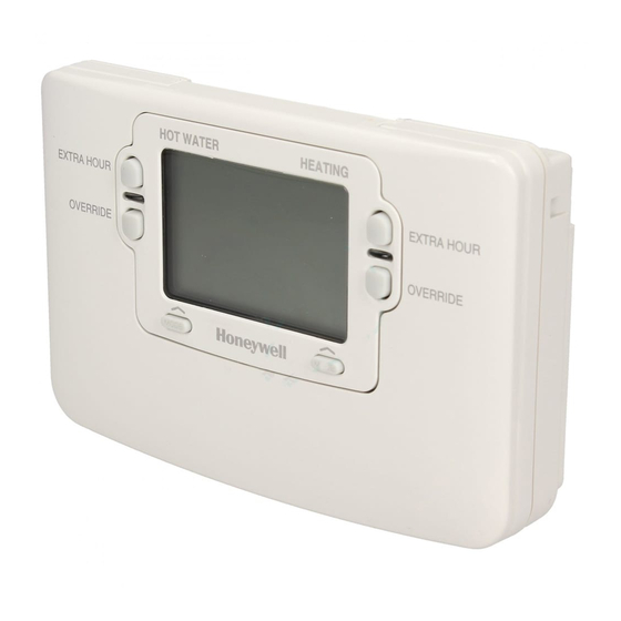
ST9400A & ST9400C Programmer
INSTALLATION INSTRUCTIONS
8
Introduction
ST9400 is an Electronic Programmer which provides accurate time
8
control for central heating systems with separate programmes for
heating and hot water. ST9400A is a 1-day version and ST9400C is a
3
7-day version.
ST9400 is suitable for replacing a wide range of Programmers on the
market, and is a direct replacement for Honeywell ST6400 Programmers
without the need for re-wiring.
ST9400 Programmers can be combined with other Honeywell controls such
as Room Thermostats, Cylinder Thermostats, Wiring Centres and Zone or
Diverting Valves to form a fully automatic central heating control system.
Mounting
If the ST9400 is replacing an existing ST6400 then the existing wall-plate
and wiring may be used, subject to any required electrical checks.
The Programmer should be mounted at a level where the display can be
seen clearly, (1.2 to1.5m from the fl oor) and the ambient temperature is
within the range of 0 to 40°C. The ST9400 is for use in normal domestic
environments.
CAUTION
Isolate power supply and make safe before wiring the unit to prevent
electric shock and equipment damage. Installation should be carried
out by a qualifi ed electrician or competent heating engineer.
To remove the unit from the wall-plate, slacken the two securing screws at
the bottom of the ST9400 and hinge the unit up to separate the two halves.
Wiring
Final Assembly
Clip the unit onto the hinges on the top of the wallplate and hinge down
into position. Tighten the two securing screws using a screwdriver.
Switch on the power – the unit will now be operating according to the
built-in programme. Note : the ST9400 is supplied with a factory set
clock for faster installation .
Refer to ST9400 User Guides for programming details.
Specifi cation
Power Supply: 230V~, 50...60Hz, 10W
Switch Action: 2 x SPDT
Switch Rating: 230V~, 50...60Hz, 3(3)A
Factory set clock
Power Reserve: lifetime battery
Programmes/Settings: permanently stored in NV RAM
Approvals: Conforms to protection requirements of
Directives 2006/95EC and 89/336EC
Mounting Options
RECOMMENDED CLEARANCE DISTANCES:
ABOVE WALLPLATE:
BELOW WALLPLATE:
LEFT/RIGHT OF WALLPLATE:
a. Surface mounting
concealed wiring
b. Flush switchbox
Fixing holes are
spaced to suit BS4662
requirements
c. Surface mounting with
surface wiring in
mini trunking
Ensure the mounting surface is supporting and fully covers the wiring
wall-plate.
ALL WIRING MUST BE IN ACCORDANCE WITH I.E.E. REGULATIONS.
THIS UNIT IS FOR FIXED WIRING ONLY.
A switch, having contact separation of at least 3mm in all poles (formerly
Class 'A'), must be incorporated in the fi xed wiring as a means of
disconnecting the supply.
The unit is a Class II (double insulated) device. A parking terminal is
provided for external earth continuity.
The system must be appropriately fused. A fuse rated at no more than
3 Amps should be installed.
The unit has 4 knockouts for surface wiring, care must be taken to ensure
that the cable or mini-trunking completely fi lls the knockout hole without
leaving any gaps.
110mm
100mm
10mm
1

Related Manuals for Honeywell ST9400A


Summary of Contents for Honeywell ST9400A
-
Page 1: Installation Instructions
Specifi cation ST9400 is an Electronic Programmer which provides accurate time Power Supply: 230V~, 50…60Hz, 10W ST7100 control for central heating systems with separate programmes for Switch Action: 2 x SPDT heating and hot water. ST9400A is a 1-day version and ST9400C is a ST9400 not connected not connected Switch Rating: 230V~, 50…60Hz, 3(3)A 7-day version. - Page 2 *NOTE 1 *NOTE 1 f. Keep pressing to step around the list of parameters, and use or buttons to change the parameter value. Alternative Wiring Connections for other Honeywell Room Thermostats g. Any parameter changes that have been confirmed with the button will be saved and used. Y-Plan, S-Plan, and C-Plan Systems W-Plan System 10-WAY WIRING STRIP...