Table of Contents
Instruction Manual
D100306X012
Fisher
657 Diaphragm Actuator
™
Sizes 30/30i through 70/70i and 87
Contents
. . . . . . . . . . . . . . . . . . . . . . . . . . . . . . . . .
. . . . . . . . . . . . . . . . . . . . . . . . . . . . .
. . . . . . . . . . . . . . . . . . . . . . . . . . . . . . . . .
. . . . . . . . . . . . . . . . . . . . . . . . . . . . . . .
. . . . . . . . . . . . . . . . . . . . . . . . . .
. . . . . . . . . . . . . . . . . . . . . . . . . . . . . . . . . .
. . . . . . . . . . . . . . . . . . . . . . . . . . .
. . . . . . . . . . . . . . . . . . . . . . . . . . .
. . . . . . . . . . . . . . . . . . . . . . . . .
. . . . . . . . . . . . . . . . . . . . . . . . . . . . . . . .
Side-Mounted Handwheel for Sizes 34/34i
. . . . . . . . . . . . . . . . . . . . . . . . .
. . . . . . . . . . . . . . . . . . . . . . . . . . . . . . .
. . . . . . . . . . . . . . . . . . . . . . . . . . . . . . . . . . .
. . . . . . . . . . . . . . . . . . . . . . . . . . . . . . . . . . .
Introduction
Scope of Manual
This instruction manual provides information on installation, adjustment, maintenance, and parts ordering for the
Fisher 657 actuator in sizes 30/30i through 70/70i and size 87. The 657-4 actuator in sizes 70/70i and 87 is also
covered. Refer to separate instruction manuals for information about the valve positioner and other accessories used
with these actuators.
Do not install, operate, or maintain a 657 actuator without being fully trained and qualified in valve,actuator, and
accessory installation, operation, and maintenance. To avoid personal injury or property damage, it is important to
carefully read, understand, and follow all the contents of this manual, including all safety cautions and warnings. If you
have any questions about these instructions, contact your
proceeding.
www.Fisher.com
. . . . . . . . . . . . . . . . . . . . . . . . .
. . . . . . . . . . . .
. . . . . . . . . . . . . . . . . . . . . . .
. . . . . . . . .
. . . . . . . . . . . . . . . . . . . . .
. . . . . . . . . . . . . . . . . . . . . . .
. . . . . . . . . . .
. . . . . . . . . . . . . . . . . .
. . . . . . .
. . . . . . . . . . . .
. . . . . . . . . . . . .
. . . . .
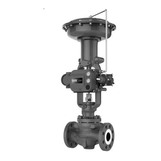
Figure 1. Fisher 657 Actuator Mounted
on an easy-e™ Valve
1
1
2
2
3
3
3
4
5
6
7
9
10
10
11
11
13
15
X1175
17
19
22
22
22
22
23
23
Emerson sales office
657 Actuator (30/30i-70/70i and 87)
. . . . . . . . . . . . . . . . . . . . . . . . .
. . . . . . . . . . . . . . . . . . . . . . . . . . . . . .
or Local Business Partner before
June 2018
. . . . .
23
. . . . .
26
31
32
Table of Contents

Related Manuals for Emerson Fisher 657


Summary of Contents for Emerson Fisher 657
-
Page 1: Table Of Contents
This instruction manual provides information on installation, adjustment, maintenance, and parts ordering for the Fisher 657 actuator in sizes 30/30i through 70/70i and size 87. The 657‐4 actuator in sizes 70/70i and 87 is also covered. Refer to separate instruction manuals for information about the valve positioner and other accessories used with these actuators. -
Page 2: Description
4. Normal operating diaphragm pressure must not exceed maximum diaphragm casing pressure and must not produce a force on the actuator stem greater than the maximum allowable out put thrust or the maximum allowable valve stem load. Contact your Emerson sales office or Local Business Partner with questions concerning maximum allowable valve stem load. -
Page 3: Educational Services
SPRING LIFTS STEM UP STEM AF3833‐A A0792‐2 Educational Services For information on available courses for Fisher 657 diaphragm actuators, as well as a variety of other products, contact: Emerson Automation Solutions Educational Services - Registration Phone: 1-641-754-3771 or 1-800-338-8158 E-mail: [email protected] emerson.com/fishervalvetraining... -
Page 4: Mounting The Actuator On The Valve
Maximum Allowable Output Thrust (table 1) or the maximum allowable valve stem load. (Contact your Emerson sales office or Local Business Partner with questions concerning maximum allowable valve stem load.) D Valve/Actuator Assembly: If the actuator and valve are shipped together as a control valve assembly, it has been... -
Page 5: Discussion Of Bench Set
Instruction Manual 657 Actuator (30/30i-70/70i and 87) D100306X012 June 2018 4. Do not connect the actuator stem to the valve stem at this time. Whenever the actuator is installed on the valve, it is recommended to perform the Bench Set Spring Adjustment procedure to verify that the actuator is still adjusted correctly. -
Page 6: Spring Verification
Instruction Manual 657 Actuator (30/30i-70/70i and 87) June 2018 D100306X012 Accurate adjustment to the bench set range can be made during the actuator mounting process by making the adjustment before the actuator is connected to the valve (see the Spring Verification procedure). Figure 4. -
Page 7: Installing The Stem Connector Assembly
8. If the measured travel is not exact, consider the spring free-length and spring rate tolerances may produce a slightly different bench set than specified. Contact your Emerson sales office or Local Business Partner for assistance. Installing the Stem Connector Assembly When installing the stem connector assembly (key 26), the actuator and valve stem threads should engage the threads of the stem connector by the distance equal to the diameter of the stem. - Page 8 Instruction Manual 657 Actuator (30/30i-70/70i and 87) June 2018 D100306X012 WARNING Install the stem connector securely before a positioner is mounted to the actuator and pressurized, using only a regulator-controlled air supply, not the positioner, to move the actuator stem. To avoid personal injury or property damage, keep hands and tools out of the actuator stem travel path while applying loading pressure to move the actuator stem in the following steps.
-
Page 9: Friction Discussion
Instruction Manual 657 Actuator (30/30i-70/70i and 87) D100306X012 June 2018 5. Screw the valve stem locknuts up against the stem connector for the size 87 actuator. For all other actuator sizes, screw the valve stem locknuts up until the indicator disk contacts the bottom of the stem connector. Do not overtighten the locknuts. -
Page 10: Deadband Measurement
Instruction Manual 657 Actuator (30/30i-70/70i and 87) June 2018 D100306X012 Deadband Measurement Deadband is caused by packing friction, unbalanced forces, and other factors in the control valve assembly. Deadband is the range a measured signal can vary without initiating a response from the actuator (see figure 5). Each actuator spring has a fixed spring rate (force divided by compression). -
Page 11: Maintenance
Instruction Manual 657 Actuator (30/30i-70/70i and 87) D100306X012 June 2018 1. Connect the loading pressure piping to the NPT internal connection in the top of the diaphragm casing. 2. For sizes 70/70i and 87 actuators, if necessary, remove the 1/4 NPT bushing if a 1/2 NPT internal connection is needed to increase connection size. - Page 12 Instruction Manual 657 Actuator (30/30i-70/70i and 87) June 2018 D100306X012 WARNING To avoid personal injury from the precompressed spring force thrusting the upper diaphragm casing (key 1) away from the actuator, relieve spring compression (step 2, below), and carefully remove casing cap screws (key 22) (step 4, below). 2.
-
Page 13: Top-Mounted Handwheel Assembly
Instruction Manual 657 Actuator (30/30i-70/70i and 87) D100306X012 June 2018 2. Position the lower diaphragm casing (key 5) on the yoke (key 9), and fasten the parts together by installing and evenly tightening the cap screws (key 8). 3. Set the actuator spring (key 6) squarely onto the spring seat (key 11). 4. - Page 14 Instruction Manual 657 Actuator (30/30i-70/70i and 87) June 2018 D100306X012 Instructions are given below for complete disassembly and assembly of the top‐mounted handwheel assembly. Perform the disassembly only as far as necessary to accomplish the required maintenance; then, begin the assembly at the appropriate step.
-
Page 15: Through 60/60I Actuators
Instruction Manual 657 Actuator (30/30i-70/70i and 87) D100306X012 June 2018 5. Place the handwheel (key 51), and the stop nut (key 54) on the handwheel stem (key 133). Tighten the hex nut to fasten the parts together. Secure the nut with the cotter pin (key 247). 6. - Page 16 Instruction Manual 657 Actuator (30/30i-70/70i and 87) June 2018 D100306X012 Disassembly for Side-Mounted Handwheel (Sizes 34-60 and 34i-60i) 1. Use step a. for size 34 through size 60 actuators, and use step b. for sizes 34i through 60i. a. For Size 34 through 60: If desired, the handwheel assembly can be removed from the actuator yoke. To do this, remove the hex nuts (keys 147 and 170) from the U-bolts (key 166 and 143) that hold the assembly to the yoke for the size 30 and size 40.
-
Page 17: Side-Mounted Handwheel For Sizes 70 And 87 Actuators
Instruction Manual 657 Actuator (30/30i-70/70i and 87) D100306X012 June 2018 7. Use step a. for size 34 through size 60 actuators, and use step b. for sizes 34i through 60i. a. For Size 34 through 60: If the handwheel assembly was removed from the yoke (key 9, figures 6, 8, or 10), remount the handjack assembly to the yoke using the dowel pins for alignment. - Page 18 Instruction Manual 657 Actuator (30/30i-70/70i and 87) June 2018 D100306X012 8. Turn the handwheel to raise the lower sleeve (key 46) until it is free of the worm gear (key 44). Lift out the lower sleeve and the key (key 47). Do not move the neutral indicator scale (key 59). 9.
-
Page 19: Casing-Mounted Adjustable Travel Stops
Instruction Manual 657 Actuator (30/30i-70/70i and 87) D100306X012 June 2018 15. Position the upper diaphragm casing (key 1) onto the diaphragm (key 2) and align the holes. Note When you replace actuator diaphragms in the field, take care to ensure the diaphragm casing bolts are tightened to the proper load to prevent leakage, but not crush the material. - Page 20 Instruction Manual 657 Actuator (30/30i-70/70i and 87) June 2018 D100306X012 The adjustable down travel stop (figure 20) limits the actuator stroke in the downward direction. To adjust, first relieve actuator loading pressure before removing the travel stop cap (key 187). Then loosen the jam nut and adjust the stop nut (keys 189 and 54) either down on the stem to limit travel, or up on the stem to allow more travel.
- Page 21 Instruction Manual 657 Actuator (30/30i-70/70i and 87) D100306X012 June 2018 5. Remove and inspect the O‐ring (keys 139); replace if necessary. 6. For all actuator sizes: Loosen the stop nut (key 54), then unscrew the travel stop stem (key 133) out of the actuator stem.
-
Page 22: Parts Ordering
11‐character part number of each needed part as found in the following Parts List. WARNING Use only genuine Fisher replacement parts. Components that are not supplied by Emerson Automation Solutions should not, under any circumstances, be used in any Fisher valve, because they may void your warranty, might adversely affect the performance of the valve, and could cause personal injury and property damage. -
Page 23: Parts List
June 2018 Parts List Description Twin Speed Nut Washer Stem Connector Assy Note Screw Yoke Extension Contact your Emerson sales office or Local Business Partner for part Indicator Adaptor numbers. Machine Screw Washer Pipe Bushing Nameplate Cap Screw Actuator Assembly... - Page 24 Instruction Manual 657 Actuator (30/30i-70/70i and 87) June 2018 D100306X012 Figure 6. Fisher 657 Actuator Sizes 30 through 60 APPLY LUB NOTE: KEY 25 IS NOT PART OF SIZE 40 CONSTRUCTIONS. 40A8765-C Figure 7. Fisher 657 Actuator Sizes 30i through 60i...
- Page 25 Instruction Manual 657 Actuator (30/30i-70/70i and 87) D100306X012 June 2018 Figure 8. Fisher 657 Size 70 Actuator APPLY LUB 50A8768-C Figure 9. Fisher 657 Size 70i Actuator APPLY LUB PARTS NOT SHOWN: KEY 7, 24, AND 249 GE71634-A...
-
Page 26: Side-Mounted Handwheel (Figure 13 Or 17)
Instruction Manual 657 Actuator (30/30i-70/70i and 87) June 2018 D100306X012 Figure 10. Fisher 657 Size 87 Actuator APPLY LUB 50A8767-C Side‐Mounted Handwheel Description U‐Bolt (figures 13 through 17) Hex Nut Handwheel Screw Lever & Pin Ass'y Description Hex Jam Nut... - Page 27 Instruction Manual 657 Actuator (30/30i-70/70i and 87) D100306X012 June 2018 Figure 11. Top‐Mounted Handwheel Assembly for Figure 12. Top‐Mounted Handwheel Assembly for Size 30/30i through 60/60i Actuators Sizes 70/70i through 87 Actuators APPLY LUB/SEALANT APPLY LUB/SEALANT NOTES: NOTES: THE TOP MOUNTED HANDWHEEL IS NOT DESIGNED FOR USE UNDER HEAVY LOAD THE TOP MOUNTED HANDWHEEL IS NOT DESIGNED FOR USE UNDER OR FOR FREQUENT USE.
- Page 28 Instruction Manual 657 Actuator (30/30i-70/70i and 87) June 2018 D100306X012 Figure 13. Side‐Mounted Handwheel Assembly for Size 34 and 40 Actuators APPLY LUBRICANT 30A8778‐D Figure 14. Side‐Mounted Handwheel Assembly for Size 34i and 40i Actuators APPLY LUBRICANT PARTS NOT SHOWN: KEY 157, 158, 159, AND 168 GE71635-A...
- Page 29 Instruction Manual 657 Actuator (30/30i-70/70i and 87) D100306X012 June 2018 Figure 15. Side‐Mounted Handwheel Assembly for Size 45, 46, 50, and 60 Actuators APPLY LUBRICANT 40A8779‐D Figure 16. Side‐Mounted Handwheel Assembly for Size 45i, 46i, 50i, and 60i Actuators APPLY LUBRICANT PARTS NOT SHOWN: KEY 158, 159, AND 168 GE71636‐A...
- Page 30 Instruction Manual 657 Actuator (30/30i-70/70i and 87) June 2018 D100306X012 Figure 17. Fisher 657 Size 70 and 87 Actuators with Side‐Mounted Handwheel APPLY LUB 50A8769-D SECTION A-A...
-
Page 31: Casing-Mounted Adjustable Up Travel Stops (Figures 18 Or 19)
Instruction Manual 657 Actuator (30/30i-70/70i and 87) D100306X012 June 2018 Figure 18. Casing‐Mounted Adjustable Up Travel Figure 19. Casing‐Mounted Adjustable Up Travel Stop for Sizes 30/30i through 60/60i Actuators Stop for Sizes 70/70i and 87 Actuators (Style 1) (Style 1) APPLY LUBRICANT APPLY LUB/SEALANT 28A1206‐C... -
Page 32: Casing-Mounted Adjustable Down Travel Stops (Figure 20)
Responsibility for proper selection, use, and maintenance of any product remains solely with the purchaser and end user. Fisher, easy-e, and FIELDVUE are marks owned by one of the companies in the Emerson Automation Solutions business unit of Emerson Electric Co. Emerson Automation Solutions, Emerson, and the Emerson logo are trademarks and service marks of Emerson Electric Co.