Service Manual
This service information is designed for experienced repair technicians only and is not designed for use by
the general public. It does not contain warnings or cautions to advise non-technical individuals of potential
dangers in attempting to service a product. Products powered by electricity should be serviced or repaired
only by experienced professional technicians. Any attempt to service or repair the product or products dealt
with in this service information by anyone else could result in serious injury or death.
There are special components used in this equipment which are important for safety. These parts are
marked by
in the Schematic Diagrams, Exploded Views and Replacement Parts List. It is essential
that these critical parts should be replaced with manufacturer's specified parts to prevent shock, fire
or other hazards. Do not modify the original design without permission of manufacture.
We suggest to handle such parts after the static electricity prevention.
It is forbidden to touch the PCB parts by bare hands during the repairing process.
CONTENTS
1.Specifications
2.Parts Identification
3.Wiring Diagram
4.Parts List
5.Troubleshooting Guide
WARNING
IMPORTANT SAFETY NOTICE
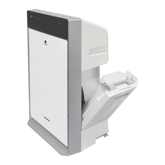
Humidifying Air Purifier
(OverSea Market)
PEG1409034CE
Version:1801
F-VXK70A
PAGE
1
2~7
8
9~13
14~24
Table of Contents

Related Manuals for Panasonic F-VXK70A

Summary of Contents for Panasonic F-VXK70A
- Page 1 Service Manual Humidifying Air Purifier (OverSea Market) F-VXK70A WARNING This service information is designed for experienced repair technicians only and is not designed for use by the general public. It does not contain warnings or cautions to advise non-technical individuals of potential dangers in attempting to service a product.
-
Page 2: Specifications
1. Specifications Model number F-VXK70A Power supply 220V 50Hz 230V 50Hz 240V 50Hz Operation mode Clean Air Clean/Humid. Air Volume settings Power consumption (W) Humidifying amount (mL/h) — — Air volume (m /min) Floor area capacity Up to 52m in a standard household room Up to 32m in a standard household room Capacity of the tank About 3.5L... -
Page 3: Parts Identification
2. Parts Identification F-VXK70A Main Body Section (2pcs) Rear Case Assembly Switch Box Section Casing Section (2pcs) Main Frame Section Humidifying Filter Section Top Cover Section Tank Section (3pcs) Stand Assembly Tray Section (4pcs) (6pcs) (For Style Reference) Front Panel Assembly... - Page 4 2. Parts Identification F-VXK70A Front Panel Assembly (6pcs) (2pcs) Top Cover Section (3pcs) If Main Circuit need to be replaced,please taken out the Display Circuit firstly when replace the lead.Otherwise,the Display Circuit will be damaged.
- Page 5 2. Parts Identification F-VXK70A Switch Box Section (2pcs) (2pcs) (2pcs) (2pcs) (2pcs) (2pcs) (2pcs) (4pcs) (3pcs) If Switch PCB Lead need to be replaced,please taken out the Display Circuit and Main Circuit firstly when replace the lead.Otherwise,the Circuit will be damaged.
- Page 6 2. Parts Identification F-VXK70A Casing Section (3pcs) Micro Switch Assembly Fuse Cord Assembly(Fuse) Fixing Place (6pcs) Rear Case Assembly (2pcs)
- Page 7 2. Parts Identification F-VXK70A Tank Section Humidifying Filter Section a a a a a a a a a a (4pcs) Stand Assembly Tray Section (4pcs) (4pcs)
-
Page 8: Parts Identification
2. Parts Identification F-VXK70A Packing Section (104) (For Malaysia,Indonesia, Singapore,Vietnam Market) a a a a a a a... -
Page 9: Wiring Diagram
3. Wiring Diagram F-VXK70A DISPLAY CIRCUIT ASSEMBLY HUMIDITY SENSOR SENSOR MOTOR MOTOR MAIN CIRCUIT ASSEMBLY MOTOR CURRENT FUSE 0.25A POWER CIRCUIT ASSEMBLY CURRENT FUSE 0.25A CURRENT FUSE 3.15A TEMP. FUSE (114 ) DUST SENSOR REED PCB MAGNET MAGNET HIGH VOLTAGE... -
Page 10: Parts List
4. Parts List F-VXK70A Main Body Section Part No. Part Name Q'ty Remark FFE01201410S Front Panel Assembly For Malaysia,Singapore,Thailand,Vietnam Market FFE01201408S Front Panel Assembly For Indonesia Market FFE41801716S Composite Air Filter Assembly FFE41801806S Composite Air Filter Assembly For Vietnam Market Only... - Page 11 4. Parts List F-VXK70A Front Panel Assembly Part No. Part Name Q'ty Remark 22 FFE03061401S Fixed Arm Holder XTB4+10CFJ Bind Tap Screw Top Cover Section Part No. Part Name Q'ty Remark 23 FFE01071402S Top Cover Assembly Include Light Guide&Clean Sign Sheet...
- Page 12 4. Parts List F-VXK70A Main Frame Section Part No. Part Name Q'ty Remark 44 FFE09021401S Dust Sensor Lead 45 FFE12500601S Dust Sensor 46 FFE02031401S Gear Box Gum 47 FFE00241401S Gear Box Assembly 48 FFE01101401S Main Frame Assembly Include Waterproof Plate...
- Page 13 4. Parts List F-VXK70A Casing Section Part No. Part Name Q'ty Remark FFE08110801S Holder Gum(A) FFE23001401S Motor Assembly FFE08120801S Holder Gum(B) FFE01191401S Cord Clip FFE08101401S Motor Holder XTB4+14CFJ Bind Tap Screw Rear Case Assembly Part No. Part Name Q'ty Remark...
-
Page 14: Parts List
4. Parts List F-VXK70A Tray Section Part No. Part Name Q'ty Remark 95 FFE05551401S Germproof Set 96 FFE05101402S Tray XTB4+14CZ Bind Tap Screw Stand Assembly Part No. Part Name Q'ty Remark 97 FFE01091404S Stand 98 FFE01251401S Caster 99 FFE01241401S Caster Shaft... -
Page 15: Troubleshooting Guide
5. Troubleshooting Guide TROUBLESHOOTING GUIDE Symptom Cause Troubleshooting 1,The machine’s power supply is 1, Check the power supply status and Without abnormal. check if the related wiring connection is Energization loosed. 2,The PCB assembly may fail. 2,Replace the PCB assembly. 1,Is the room ventilated,or has laid the 1,If the floor is carpeted,the humidity may The humidity... - Page 16 5. Troubleshooting Guide Corrective Maintenance Fault Phenomena:1,Air Volume Indicator Light Flashing 2,Machine out of operation Cause:1,Motor's rotating speed is abnormal. 2,Motor out of operation Substitute Part: Motor,Power Circuit Assembly Abnormal Check if the motor lead wire terminals disconnect Reconnect the motor lead wire terminal with the power circuit assembly on the power circuit assembly Normal...
- Page 17 5. Troubleshooting Guide The output voltage of the circuit assembly terminal is used for checking when machine detected. DISPLAY CIRCUIT ASSEMBLY HUMIDITY SENSOR SENSOR MOTOR MOTOR +15V +15V +15V GND +5V MAIN CIRCUIT ASSEMBLY MOTOR CURRENT FUSE 0.25A POWER CIRCUIT ASSEMBLY +15V CURRENT FUSE 0.25A...
- Page 18 5. Troubleshooting Guide Setting method of checking mode Body Plug in the power supply.Press Operation Body Operation Indicating confirmation Body Press Operation Body Operation Indicating confirmation Body Press Operation Body Operation Indicating confirmation...
- Page 19 5. Troubleshooting Guide Setting method of checking mode Body Press Operation Body Operation Indicating confirmation Body Press Operation Body Operation Indicating confirmation 1.Press Float Assembly 2.Unlock Float Assembly 1.Slope The Machine 2.Machine Reset Body Press Operation Body Operation Indicating confirmation...
- Page 20 5. Troubleshooting Guide Setting method of checking mode Body Use a cloth to wipe the dust sensor to confirm the status of dust sensor Operation Body Operation Indicating confirmation Body Use the alcoho spray to odor circuit assembly to confirm the status Operation of the odor circuit assembly Body...
- Page 21 5. Troubleshooting Guide Setting method of checking mode Body Somebody walking into the rang of Human activity sensor Operation (Confirm Human activity sensor) Body Operation Repetition Indicating confirmation Body Press Operation Body Operation Indicating confirmation (OK) Body Operation Indicating confirmation (NG)
- Page 22 5. Troubleshooting Guide Setting method of checking mode Body Press Operation Body Operation Indicating confirmation Body Press Operation Body Operation Indicating confirmation Body Press Operation Upper louver set position Upper louver swing Body Operation Indicating confirmation Upper louver full opening Upper louver swing Upper louver was ajar...
- Page 23 5. Troubleshooting Guide Setting method of checking mode Body Press Operation Body Operation Indicating confirmation Front panel raise to top position with buzzing Body Press Operation Body Operation Indicating confirmation Front panel fall to bottom position with buzzing Body Press Operation Body Operation...
- Page 24 5. Troubleshooting Guide Setting method of checking mode Body Press Operation Body Operation Indicating confirmation Humidity filter return to operate Mode check is complete and unplug the power supply.
-
Page 25: Troubleshooting Guide
5. Troubleshooting Guide Setting method of checking mode Setting method of checking mode is used to check the working status of all features of the machine. Indicator Light's Notes 1,Function icon (Black is light off, color is light on ) 2,Rectangular bar is air pollution indicator (Display color includes blue, red.