Panasonic AG-HMX100P Operating Instructions Manual
Digital av mixer
Hide thumbs
Also See for AG-HMX100P:
- Operating instructions manual (48 pages) ,
- Operating instructions manual (37 pages) ,
- Operating instructions manual (93 pages)
Table of Contents
Quick Links
See also:
Operating Instructions Manual
1
Volume
Note that Operating Instructions Vol. 1 describes basic
operations of the digital AV mixer.
For instructions on advanced operations of the digital
AV mixer, refer to Operating Instructions Vol. 2 (pdf file)
contained in the supplied CD-ROM.
Before operating this product, please read the instructions carefully and save this manual for future use.
SS0810RI0 -PS D
Printed in Japan
Operating Instructions
Model No.
Model No.
Digital AV Mixer
AG-HMX100P
AG-HMX100E
Vol.1
ENGLISH
VQT2U23
Table of Contents

Related Manuals for Panasonic AG-HMX100P


Summary of Contents for Panasonic AG-HMX100P
-
Page 1: Operating Instructions
Operating Instructions Vol.1 Digital AV Mixer AG-HMX100P Model No. AG-HMX100E Model No. Volume Note that Operating Instructions Vol. 1 describes basic operations of the digital AV mixer. For instructions on advanced operations of the digital AV mixer, refer to Operating Instructions Vol. 2 (pdf file) contained in the supplied CD-ROM. - Page 2 AC plug. Please provide connection to the ground. Wrongly wired contact either a local or foreign Panasonic extension cords are a major cause of fatalities. The fact that the equipment operates selecting an alternate AC plug.
-
Page 3: Important Safety Instructions
Read this first! (For AG-HMX100P) (continued) IMPORTANT SAFETY INSTRUCTIONS that produce heat. wider than the other. A grounding-type plug has two blades and a third grounding prong. The wide blade or the third prong are provided for your safety. If the provided plug does not fit into your outlet, consult an electrician for replacement of the obsolete outlet. - Page 4 Read this first! (For AG-HMX100P) (continued) FCC NOTICE (U.S.A.) Declaration of Conformity Trade Name: Panasonic One Panasonic Way, Secaucus, NJ07094 Support contact: 1-800-524-1448 Operation is subject to the following two conditions: interference that may cause undesired operation. modifications. Note: This equipment has been tested and found to comply with the limits for a class B digital device, pursuant to Part 15 of installation.
- Page 5 Read this first! (For AG-HMX100E) WARNING: CAUTION: This equipment must be earthed. The mains plug of the power supply cord shall To ensure safe operation, the three-pin plug remain readily operable. must be inserted only into a standard three-pin power point which is effectively earthed through installed near the equipment and shall be easily normal household wiring.
-
Page 6: Caution For Ac Mains Lead
Read this first! (For AG-HMX100E) (continued) Caution for AC Mains Lead FOR YOUR SAFETY PLEASE READ THE FOLLOWING TEXT CAREFULLY. This product is equipped with 2 types of AC mains cable. One is for continental Europe, etc. and the other one is Appropriate mains cable must be used in each local area, since the other type of mains cable is not suitable. - Page 7 4. Connect the apparatus to another power outlet where the power is not shared by any other appliances. Pursuant to at the directive 2004/108/EC, article 9(2) Panasonic Testing Centre Panasonic Service Europe, a division of Panasonic Marketing Europe GmbH Winsbergring 15, 22525 Hamburg, F.R. Germany...
-
Page 8: Table Of Contents
Contents Volume 1 (This Book) Requests on Use ........9 Setting the Bus [BUS] ..........27 ...... 27 Setting the Audio Faders ....27 OVERVIEW..........10 Screen .. 28 ....29 Features ............... 10 ....... 30 AV Mixer Functions ............ 11 Using Still Pictures or Movies as Internal Video Accessories .............. -
Page 9: Requests On Use
Requests on Use sound. The liquid crystal parts are highly precise with 99.99 % of the pixels effective. This leaves less than 0.01 % of pixels that may not light or may remain on all the time. These phenomena are normal. The response speed, brightness, and color contrast of the liquid crystal parts vary with the operating temperature and viewing angle. -
Page 10: Overview
OVERVIEW functions of video switchers, digital video effectors, and audio mixers. Features Video switching/combining effects Various digital effects mirror, mosaic, and paint. The screen display mode can be selected from Field and Frame for the still, strobe, and multi- strobe effects. Audio mixing Ten sets of audio input sources can be adjusted and mixed. -
Page 11: Av Mixer Functions
AV Mixer Functions The following shows the operation examples for video production with the AV mixer functions. Basic Operation (see “Operation Applied Operation (see the pdf manual in the Manual Volume ”) CD-ROM, “Operation Manual Volume ”) Configuring a system ( Starting the unit (... -
Page 12: Accessories
Accessories NOTE Be sure to appropriately dispose of the packing material when you have unpacked the product. Consult your supplier regarding purchase of accessories. -
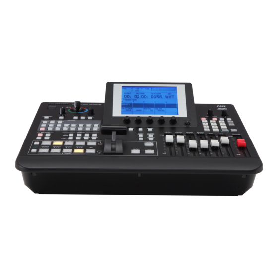
Page 13: Components And Functions
Components and Functions Operation Panel (Front) 6 7 8 POWER X / Y P B / P R POS. X 128 Y 220 Z 127 EVENT ME TIME PATTERN 04:25 0016 WHT PHONES TIME ASPECT TRANSITION MODIFY PROJECTOR/ SCENE PATTERN WIDTH COLOR PATTERN... - Page 14 . (period) key* ( pages 32, Vol.2-21) 27 PATTERN area ( pages 23, 34, 36, Vol.2-6, Vol.2-7) (1) (2) (3) SHIFT key ( pages 27, 28, 30, 32, 33, Vol.2-4, Vol.2-9, Vol.2-10, Vol.2-13, Vol.2-15) PATTERN (confirm) key* EFFECTS REVERSE 15 MASTER fader ( page 33) CHROMA P in P 16 MIC fader (...
- Page 15 Connector Area (Rear) For devices and signals which can be connected to NOTE For the DVI-I IN connector and DVI-D IN connectors, shielded ( DVI cables with noise suppression core are recommended. ( For transmitting HD-SDI signals via the SDI IN 1 to 4 connectors and SDI OUT connectors, cables equivalent or superior to the 5C-FB or 5C-FW cable are recommended.
-
Page 16: Basic Operation
System camera G/L external sync signal* SDI (video and audio) input ADV-REF Multi- SDI output Professional-use Professional-use AG-HMX100P/HMX100E view monitor output SDI IN 1 SDI OUT PGM SDI IN 2 SDI OUT PVW SDI IN 3 (video SDI OUT MULTI VIEW... -
Page 17: Hd Video Processing System
Professional-use Preview output G/L external SDI (video and camera sync signal* audio) input ADV-REF Multi- SDI output Professional-use AG-HMX100P/HMX100E Professional-use view camera monitor output SDI IN 1 SDI OUT PGM SDI IN 2 SDI OUT PVW SDI IN 3 SDI OUT MULTI VIEW... -
Page 18: System With External Controller
Preview output sync signal* camera SDI (video and audio) input ADV-REF RS-232C Multi- SDI output Professional-use Professional-use AG-HMX100P/HMX100E view camera LCD monitor SDI IN 1 output SDI OUT PGM SDI IN 2 SDI OUT PVW SDI IN 3 SDI OUT MULTI VIEW... -
Page 19: Power-On
Power-On Use the supplied power cord to connect this unit to an AC power source. Press the POWER button. To specify the initial state of the unit when it is restarted Preset mode: The last settings are restored when the unit is restarted. The factory default setting is this mode. Reset mode: previous state including those of the [SETUP] menu. -
Page 20: Setting Screen
Setting Screen The following shows the basic configuration of the setting screen. POS. X 128 Y 128 Z 196 FAN STOP EVENT ME TIME PATTERN 2:00 3044 WHT VIDEO EFFECTS CH A MOSAIC SIZE DEFOCUS LEVEL MONO 1 Joystick, rotary Z control settings, and 3D display ... -
Page 21: Basic Operation Of Menus
6 Menu display area To select the menu Shows the setting items and values of the currently selected menu. EFFECTS] menus, press the corresponding menu button. The leftmost column has the setting items and the second to fourth columns have the setting values. (The For other menus, press the operation button related to the leftmost column shows the setting values when the settings. -
Page 22: [Setup] Menu
[SETUP] Menu Setting the Startup Mode [MODE] (Setup Operation) Screen specify how to reproduce the stored settings when this unit When the SETUP button is pressed, the [SETUP] menu screen appears as shown below. Rotary 1 Rotary 2 Rotary 3 Rotary 4 Rotary 5 MODE... - Page 23 Position setting values of patterns registered as direct patterns The entered number is displayed at the position of Changing Direct Patterns the pattern number. [DIRECT PATTERN] Volume 2. NOTE If the pattern corresponding to the entered number is already assigned to other button, the button flashes.
-
Page 24: Setting Video And Audio Input Sources
Example of DIRECT PATTERN KEY screen The video and audio input source settings are stored individually for the following three cases. POS. X 128 Y 128 Z 196 EVENT ME TIME PATTERN 1:00 3002 WHT The stored settings are read out each time the system format is changed. - Page 25 You cannot set the combinations of video and audio NOTE input sources shown in the table below. (The settings are The same input sources are assigned to the A/PROG bus and automatically changed to available values.) the B/PRESET bus. When the video input is HDMI, only two channels of audio It is impossible to assign different sources to each bus.
-
Page 26: Setting The Video Format
When 3D mode is set to other than [OFF], “--” appears and 720/59p 1080/50i the system format cannot be changed. 1080/59i If [HDMI] is selected, the HDMI input signal is output as HDMI is from the DVI-D OUT connector, disabling the AV mixer functions including video switching effects. AG-HMX100P... -
Page 27: Setting The Bus [Bus]
When the 3D mode is [OFF] ( page Vol.2-25), the system Use the rotary 3 control to select the audio format of this unit is the one set in the [VIDEO FORMAT] submenu of the [SETUP] menu. When the 3D mode is other input (of the SDI input selected in Step 1) which than [OFF], the system format of this unit is the one set you want to assign the L channel by setting... - Page 28 To set the audio output format and the operation of audio faders The following table shows the output method and audio input sources assigned to the faders for each setting. Setting Output Method SOURCE 1/5 Fader SOURCE 2/6 Fader SOURCE 3/7 Fader SOURCE 4/8 Fader Sound output of the selected input source...
- Page 29 Use the rotary 1 control to set the internal video output type If [CUSTOM1] or [CUSTOM2] is selected in Step 2, use the joystick and rotary Z control to set the [P ] and [P ] values in the range of 0 to 255 and the [Y] value in the range of 16 to 235 can be saved in internal memory and used as internal for selecting the back matte video color.
-
Page 30: Screen
If other than [CUSTOM1] and [CUSTOM2] is The page count ratio for the title and still picture or movie selected. [SETUP] menu ( create and display still pictures and movies. Use the joystick and rotary Z control to set the ] and [P ] values in the range of 0 to 255 pages are displayed in the internal video display area in the... - Page 31 To save still pictures used as internal To save movies used as internal video video Rotary 1 Rotary 2 Rotary 3 Rotary 4 Rotary 5 MEMORY PAGE FRAME MODE Rotary 1 Rotary 2 Rotary 3 Rotary 4 Rotary 5 REPEAT WRITE MEMORY PAGE...
-
Page 32: Using Video Input From Pc [Pc1]
Using Video Input from PC [PC1] Set [FRAME] to the number of frames to preview using the rotary 3 control. connector. To preview the movie, select a value equivalent For using video created on PC, it is necessary to allocate to or smaller than the number of frames of the movie. -
Page 33: Switching Or Combining Of Video
Switching or Combining of Video Procedures of switching or combining video are described Checking (Previewing) Video and below. Sound Selecting Source Video and Sound This section describes the procedure of selecting source video and sound to be provided with effects or mixed on this unit. -
Page 34: Ab Transition
NOTE Process the selected pattern by applying If the AUDIO FOLLOW VIDEO button has been pressed to turn effects including border, shadow, and trail on to interlock the audio faders with the transition lever or the ( page Vol.2-3). audio level of input source 5 to 8 has been adjusted with the SHIFT key pressed, the audio fader settings may not match the actual audio level. -
Page 35: Program Preset Transition
Program Preset Transition To select a pattern The currently selected pattern number is shown in the Program preset transition is an effect of switching from event number, transition, pattern number, and internal video display area of the setting screen ( PATTERN 0001 switching direction only from preset video to program video... - Page 36 For luminance keying, chroma keying or To use the Scene Grabber function external keying, apply effects such as slice and slope to the key video ( page Vol.2-6). The scene grabber function allows you to move the image Set the pattern position (where the key is ...
- Page 37 SDI IN 3 SDI IN 4 ( The dissolve effect is applied. AG-HMX100P/HMX100E NOTE It is impossible to use a pattern other than transition patterns for DSK. If a pattern unavailable for DSK is selected, the DSK EFFECTS button flashes.
-
Page 38: Fade
Fade Fade is an effect of gradually erasing images or decreasing The following diagram shows an example of fade-out. Set the fading method in the [FADE] submenu of the [DSK FADE] menu ( page Vol.2-11). Set the FADE transition time (from fading start to end) (... -
Page 39: Before Calling For Service
Before Calling for Service Troubleshooting AG-HMX100P/HMX100E-related problems Problem What to Check The power cannot be switched on. There is no picture. There is no color. There is no sound. The image does not change even when the transition lever is moved. -
Page 40: Specifications
Specifications Power source: Power consumption: 60 W Indicates safety information. [General] Operating temperature: Operating humidity: Storage temperature: Storage humidity: Mass: [SYSTEM] System format: [VIDEO] Sampling frequency Video format: 10 bits Internal processing: 4 : 2 : 2 : 4 12 bits [AUDIO] Sampling frequency: Frequency response:... - Page 41 [VIDEO INPUT/OUTPUT] Analog composite input BNC x 2 sets, 1.0 V[p-p], 75 termination BNC x 4 sets standards External sync signal input auto termination standards standards standards MULTI VIEW output: Advanced reference output BNC x 1, 75 Analog composite signal [AUDIO INPUT/OUTPUT] standards high impedance, unbalanced...
-
Page 42: Signal Format Supported On The Unit
[OTHER] Maximum current: 50 mA or less GPI input: Signal Format Supported on the Unit Format VIDEO HDMI DVI-D DVI-I NTSC — — — — — — — — — — — — — — — — — — — —... -
Page 43: Signal Format Supported On The Unit In 3D Mode
Signal Format Supported on the Unit in 3D Mode Format VIDEO HDMI DVI-D DVI-I NTSC — — — — — — — — — — — — — — — — — — — — — — — — — —... -
Page 44: Index
Index Symbols Bus setting ..............27 ................14 ..............13, 35, 20 ........... 13, 34, 36, 13 ..............13, 35, 20 ..............6 ............. 14, 32, 21 Border ............... 7 Numbers Color canceling ............6 Cropping ..............7 ................25 Effects ............... - Page 45 Setting screen ............28 buses ............14, 13, 15 ........... 13, 28 ........14 ............28 STILL buttons ............14 ............. 14 ........14 ......13, 20, 28, 30, 34, 36, 4, 6, 13 Effects to video, applying ..........13 Environment settings ............
- Page 46 Still ................15 STILL buttons ..............15 ............. 14, 34 Still pictures, displaying ..........31 Still pictures, saving as internal video ......31 Strobe ................15 ............15 [PAINT] ................16 ..............26 Paint effect ..............16 ..............26 [PAN] ................17 System configuration examples ........
- Page 47 MEMO...
- Page 48 This symbol is only valid in the European Union. If you wish to discard this product, please contact your local authorities or dealer and Panasonic Corporation Web Site: http://panasonic.net Panasonic Solutions Company 3 Panasonic Way, Secaucus, NJ 07094 Tel: 877-803-8492 www.panasonic.com/broadcast e-mail: [email protected] Panasonic Canada Inc. 5770 Ambler Drive, Mississauga, Ontario L4W 2T3 Tel: 905-624-5010 Panasonic de México S.A.