
Related Manuals for Canon imagerunner C5180


Summary of Contents for Canon imagerunner C5180
- Page 1 Color imageRUNNER C5180/C4580/C4080 Series SERVICE MANUAL DU7-1174-000 AUGUST 2006 REV. 0 COPYRIGHT 2006 CANON INC. CANON imageRUNNER C5180/4580/4080 REV. 0 PRINTED IN U.S.A.
- Page 2 This manual may contain technical inaccuracies or typographical errors due to improvements or changes in products. When changes occur in applicable products or in the contents of this manual, Canon will release technical information as the need arises. In the event of major changes in the contents of this manual over a long or short period, Canon will issue a new edition of this manual.
- Page 3 Introduction Symbols Used This documentation uses the following symbols to indicate special information: Symbol Description Indicates an item of a non-specific nature, possibly classified as Note, Caution, or Warning. Indicates an item requiring care to avoid electric shocks. Indicates an item requiring care to avoid combustion (fire). Indicates an item prohibiting disassembly to avoid electric shocks or problems.
- Page 4 Introduction The following rules apply throughout this Service Manual: 1. Each chapter contains sections explaining the purpose of specific functions and the relationship between elec- trical and mechanical systems with reference to the timing of operation. In the diagrams, represents the path of mechanical drive; where a signal name accompanies the symbol, the arrow indicates the direction of the electric signal.
-
Page 5: Table Of Contents
Contents Contents Chapter 1 Introduction 1.1 System Construction..................1-1 1.1.1 System Configuration with Pickup/Delivery Accessories [USA] ......1-1 1.1.2 System Configuration with Printing/Transmission Accessories [USA] ....1-2 1.1.3 Functions of Printing/Transmission Accessories ..........1-3 1.1.4 Overview of Printing/Transmitting Accessories............. 1-3 1.2 Product Specifications.................. - Page 6 Contents 1.2.7.1 Print Speed ......................... 1-32 1.2.7.2 Print Size ..........................1-38 1.2.7.3 Others ..........................1-39 1.2.7.4 Reader Unit Specifications ....................1-40 Chapter 2 Installation 2.1 Making Pre-Checks ................... 2-1 2.1.1 Points to Note ......................2-1 2.1.2 Spatial Requirements ....................2-3 2.1.3 Order of Installing Accessories ................
- Page 7 Contents 2.6 Installing the Card Reader ................2-31 2.6.1 Checking Contents (Card Reader-D1) ..............2-31 2.6.2 Installation Procedures.................... 2-31 2.6.3 Installation Procedure in the imageWARE Accounting Manager (henceforth: iWAM) environment...................... 2-33 2.7 Installing the Original Tray ................2-33 2.7.1 Checking Contents (Document Tray-J1)............. 2-33 2.7.2 Installation Procedures ...................
- Page 8 Contents 5.2.2 SRAM Circuit Board....................5-4 5.3 Start-Up Sequence .................... 5-5 5.3.1 Overview........................5-5 5.3.2 Start-Up Sequence ....................5-5 5.4 Actions when HDD Error................... 5-9 5.4.1 E602 Details....................... 5-9 5.5 Image Processing .................... 5-13 5.5.1 Overview of the Flow of Image Data ..............5-13 5.5.2 Reader Input Image Processing ................
- Page 9 Contents 6.3 Various Control Mechanisms ................6-9 6.3.1 Controlling the Scanner Drive System ..............6-9 6.3.1.1 Overview ..........................6-9 6.3.1.2 Controlling the Scanner Motor..................6-10 6.3.2 Enlargement/Reduction ..................6-11 6.3.2.1 Changing the Magnification in Main Scanning Direction..........6-11 6.3.2.2 Changing the Magnification in Sub Scanning Direction ..........6-11 6.3.3 Controlling the Scanning Lamp ................6-11 6.3.3.1 Overview ..........................
- Page 10 Contents 7.1.1 Overview........................7-1 7.1.2 Shading Correction ....................7-1 Chapter 8 Laser Exposure 8.1 Construction......................8-1 8.1.1 Specifications, Control Mechanisms, and Functions........... 8-1 8.1.2 Major Components....................8-2 8.1.3 Construction of the Control System ............... 8-3 8.2 Basic Sequence ....................8-4 8.2.1 Basic sequence of operation ...................
- Page 11 Contents 9.2.2 Image Formation Process (image formation) ............9-8 9.2.3 Image Formation Process (transfer) ............... 9-9 9.3 Basic Sequence....................9-10 9.3.1 At Power-On (1) ....................... 9-10 9.3.2 At Power-On (2) ....................... 9-11 9.3.3 During Copying/Printing Operations (normal speed) ......... 9-12 9.3.4 Making Copies/Prints (half speed) ................
- Page 12 Contents 9.8 Transfer Unit ..................... 9-46 9.8.1 Outline of the Transfer Unit ................... 9-46 9.8.1.1 Outline of the Transfer Unit ....................9-46 9.8.1.2 Transfer Unit Drive Control....................9-47 9.8.2 Controlling the Transfer Bias ................. 9-48 9.8.2.1 Transfer Bias Control......................9-48 9.8.3 Cleaning ........................
- Page 13 Contents 10.1.7 Route of Dive ......................10-7 10.2 Basic Sequence..................... 10-8 10.2.1 Basic Sequence of Operations at Power-On............. 10-8 10.2.2 Basic Sequence of Operations in Response to a Press on the Start Key ..10-8 10.3 Detecting Jams....................10-9 10.3.1 Delay Jams ......................10-9 10.3.1.1 Delay Jam in the Cassette Pickup Assembly ..............
- Page 14 Contents 10.10.5 Re-pickup Roller ....................10-39 10.10.6 Pickup Roller ...................... 10-40 10.10.7 Feed Roller ......................10-41 10.10.8 Separation Roller ....................10-41 10.10.9 Cassette Pickup Motor ..................10-42 10.10.10 Cassette Retry Paper Sensor ............... 10-43 10.10.11 Cassette Paper Sensor .................. 10-45 10.10.12 Cassette Paper Level Sensor (A/B) .............
- Page 15 Contents 10.10.47 Face-Down Delivery Roller 1 .................10-95 10.10.48 Face-Up Delivery Roller ..................10-98 10.10.49 Delivery Vertical Path Roller 1 ..............10-100 10.10.50 Delivery Vertical Path Roller 2 ..............10-101 10.10.51 Face-Down Delivery Motor ................10-102 10.10.52 Delivery Vertical Path Motor .................10-102 10.10.53 Face-Down Delivery Sensor 1 ..............10-103 10.10.54 Center Delivery Tray Full sensor ..............10-104 10.10.55 Face-Down Delivery Sensor 2 ..............10-105 10.10.56 Delivery Vertical Path Cover Open/Closed Sensor ........10-106...
- Page 16 Contents 11.3 Belt Pressurizing Mechanism ..............11-30 11.3.1 Pressurizing mechanism of pressure belt ............11-30 11.4 Protective Functions ..................11-31 11.4.1 Power break due to thermo-switch operation at unusual temperature rise. 11-31 11.5 Parts Replacement Procedure..............11-32 11.5.1 Fixing Drive Unit ....................11-32 11.5.2 Fixing Assembly ....................
- Page 17 Contents 12.4.1.3 Power Supply Path to Reader Unit ................12-9 12.4.1.4 Power Supply Path in Printer ..................12-10 12.4.1.5 Power Supply Path in Pedestal (Accessory) ............12-12 12.4.2 Rated Output of DC Power Supply PCB ............12-12 12.4.2.1 Rated Output of DC Power Supply PCB ..............12-12 12.4.2.2 Rated Output of the Optional DC Power Supply PCB..........
- Page 18 Contents 12.5.28 ITB Cooling Fan ....................12-50 12.5.29 Face-down Tray Cooling Fan (rear/ front) ............. 12-51 12.5.30 Cleaner Fan ....................... 12-52 12.5.31 Manual Feed Cooling Fan ................12-52 12.5.32 Fixing Heat Discharge Fan ................12-53 12.5.33 Power Supply Exhaust Fan ................12-54 12.5.34 IH Power Supply Cooling Fan .................
- Page 19 Contents 15.1.3 Printer Unit ......................15-1 15.2 Durables and Consumables ................ 15-2 15.2.1 Outline........................15-2 15.2.2 Reader Unit ......................15-2 15.2.3 Printer Unit ......................15-2 15.3 Scheduled Servicing Basic Procedure ............15-4 15.3.1 Scheduled Servicing Basic Procedure ............... 15-4 15.3.2 Scheduled Servicing (Reader Unit)..............15-5 15.3.3 Scheduled Servicing (Printer Unit) ..............
- Page 20 Contents 16.7.1 Adjusting the Horizontal Registration When Replacing the Pickup Cassette 16- 16.7.2 Adjusting the Horizontal Registration When Replacing the Duplex Unit..16-17 Chapter 17 Correcting Faulty Images 17.1 Outline of Electrical Components ..............17-1 17.1.1 Clutch/Solenoid ..................... 17-1 17.1.2 Motor ........................17-1 17.1.3 Fan ..........................
- Page 21 Contents 19.5.2 FEEDER ......................19-122 19.5.3 SORTER ......................19-122 19.5.4 BOARD ........................19-123 19.6 TEST (Test Print Mode) ................19-124 19.6.1 COPIER .......................19-124 19.7 COUNTER (Counter Mode)..............19-128 19.7.1 COPIER .......................19-128 Chapter 20 Upgrading 20.1 Outline......................20-1 20.1.1 Function/ Operation Overview ................20-1 20.1.2 Points to Note at Downloading................
- Page 22 Chapter 1 INTRODUCTION...
- Page 23 Contents Contents 1.1 System Construction..................1-1 1.1.1 System Configuration with Pickup/Delivery Accessories [USA] ......1-1 1.1.2 System Configuration with Printing/Transmission Accessories [USA] ....1-2 1.1.3 Functions of Printing/Transmission Accessories ..........1-3 1.1.4 Overview of Printing/Transmitting Accessories............. 1-3 1.2 Product Specifications..................1-5 1.2.1 Names of Parts ......................1-5 1.2.1.1 External View ........................
-
Page 24: System Construction
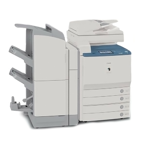
Chapter 1 1.1 System Construction 1.1.1 System Configuration with Pickup/Delivery Accessories [USA] [14] [10] [11] [12] [13] F-1-1 [1] Finisher-X1 [8] Platen Cover + Reader Unit (standard) [2] Saddle Finisher-W2 [9] Document Tray-J1 (standard) [3] Finisher-W1 [10] Paper Deck-Y1 [4] Puncher Unit-AH1 [11] Card Reader-D1 [5] Copy Tray-N1 [12] Plain Pedestal-E1... -
Page 25: System Configuration With Printing/Transmission Accessories [Usa]
Chapter 1 1.1.2 System Configuration with Printing/Transmission Accessories [USA] [10] [11] [12] [13] [14] [15] [16] [17] F-1-2 Super G3 FAX Board-V1 Super G3 Multi-Line FAX Board-H1 Main Controler Borad (Sub RB-A) Voice Guidance Kit-A2 Security Expansion Board-E1 imagePASS-H1 ColorPASS-GX100 Color UFR II/PCL Printer Kit-N1 (licence*) Color PS Printer Kit-N1 (licence) [10]... -
Page 26: Functions Of Printing/Transmission Accessories
[17] Remote Operator's Software Kit-A2 (licence) *: Need [4] at the same time. 1.1.3 Functions of Printing/Transmission Accessories Transmitting --> - Canon Color Universal Send Kit - iR512MB Expansion RAM Searchable PDF --> - Universal Send Searchable PDF Kit Faxing -->... - Page 27 - Encrypted PDF Extension Kit Adds function of setting password for PDF created by this product and encrypting it. Requires a Canon Color Universal Send Kit. - Universal Send Searchable PDF Kit Perform the OCR (optical character reader) processing for the document scanned by this machine and add the function to generate text search-capable PDF (searchable PDF).
-
Page 28: Product Specifications
Chapter 1 1.2 Product Specifications 1.2.1 Names of Parts 1.2.1.1 External View [18] [17] [16] [15] [14] [13] [12] [11] [10] F-1-3 [1] Reader left cover [10] Fixing feeding unit cover [2] Copyboard cover [11] Lower left cover [3] Reader front cover [12] Rear left cover (lower) [4] Card reader cover [13] Left rear cover (lower) - Page 29 Chapter 1 [17] [16] [15] [14] [13] [12] [11] [10] F-1-4 [1] Reader right cover [10] Rear right cover [2] Copyboard glass [11] Pick-up vertical path lower cover [3] Reader rear cover [12] Pick-up vertical path cover [4] Reader joint cover [13] Front right cover [5] Left rear cover (upper) [14] Manual feed pick-up tray...
-
Page 30: Cross Section
Chapter 1 1.2.1.2 Cross Section [1] [2] [3] [4] [50] [49] [48] [47] [46] [45] [44] [43] [10] [42] [11] [41] [12] [40] [13] [39] [14] [38] [15] [16] [37] [17] [36] [18] [19] [35] [34] [20] [33] [32] [31] [30] [29] [28]... - Page 31 Chapter 1 [9] Pattern reader unit [34] Fixing belt tension roller [10] Manual pickup tray unit [35] Pressure roller [11] Manual feed roller [36] Duplex feed roller 1 [12] Pre-registration roller [37] Fixing roller [13] Manual feed separation roller [38] Inside delivery roller [14] Re-pickup roller [39] Face-up delivery roller [15] Pickup vertical path roller...
-
Page 32: Using The Machine
Chapter 1 1.2.2 Using the Machine 1.2.2.1 Turning On the Power Switch The machine is equipped with 2 power switches: main power switch and control panel power switch. The machine goes on when the main power switch is turned on (i.e., other than in power save mode, low power mode, sleep mode). - Page 33 Chapter 1 Do not turn off the main power while the progress bar is indicated, during which access is made to the HDD. If deprived of power, the HDD can suffer a fault (E602). Starting up. Please wait. F-1-7 1-10...
-
Page 34: Points To Note About Turing Off The Main Power Switch
Chapter 1 1.2.2.2 Points to Note About Turing Off the Main Power Switch When the main power switch is turned OFF, be sure to press the power switch of the control panel for 3 sec or more and execute shutdown sequence. When Sending Data to the Printer or Using the Fax Unit Be sure that the Execution/Memory lamp on the control panel is off before operating the main power switch. - Page 35 Chapter 1 When Downloading Is Under Way Do not turn off the control panel switch or the main power switch. (Turning off the main power switch while downloading is under way can disable the machine.) F-1-9 1-12...
-
Page 36: Control Panel
Chapter 1 1.2.2.3 Control Panel ON/OFF [18] [17] [8] [9] [10] [11] [12] [13][14][15][16] F-1-10 [1] Image contrast adjustment dial [10] User mode key (initial setting/registration) [2] Counter check key [11] Keypad [3] Power Save key [12] Execute/Memory indicator lamp [4] Control panel power switch [13] Error indicator lamp [5] Place to put touch pen... - Page 37 Chapter 1 Mode Description Enable/disable buzzer Input correct: *On, Off Input incorrect: On, *Off Supply alert: On, *Off Alert: *On, Off Job end: *On, Off Residual original: On, *Off Display Remaining Paper *On, Off Message Priority on text/photo upon Text, *photo selection of auto color Display the back mode shortcut On, *Off...
- Page 38 Chapter 1 Mode Description Switch pickup method *Speed, print Standard mode for local print Paper select: *auto/pickup position select Print count: *1 to 9999 Sorter: When the finisher is not attached, when copy tray unit H1/XX is attached: non-sort, *sort, rotation sort, group sort, rotation group When the finisher M1 is attached: non-sort, sort, *shift sort, group, shift group, staple (corner) When the finisher T1/saddle finisher T2 is attached: non-sort, sort,...
-
Page 39: Timer Settings
Chapter 1 1.2.3.2 Timer Settings *: Factory default. T-1-2 Mode Description Time fine adjustment 00:00 to 23:59 (1-min increments) Auto sleep time 10 min, 15 min, 20 min, 30 min, 40 min, 50 min, *1 hr, 90 min, 2 hr, 3 hr, 4 hr Auto clear time 0: none;... -
Page 40: Report Settings
Chapter 1 1.2.3.4 Report Settings "Report Settings" is the item displayed when optional equipment is attached. *: Factory default. T-1-4 Mode Description Settings: send TX report *For error only: On, Off Report with TX image: *On, Off Report with color TX image: On, *Off Activity report Every 100 communications auto print: *On, Off Daily activity report time: On, *Off... -
Page 41: System Settings
Chapter 1 1.2.3.5 System Settings *: Factory default. **: Indicates items that appear only when the appropriate optional equipment is attached. ***: Indicates items that appear when optional equipment is attached. (For N-model, it is the standard equipment.) *1: The machine may not enter the sleep mode completely, depending on the status and type of installed MEAP applications. - Page 42 Chapter 1 Mode Description System box settings System box PIN : Seven digit number Use Fax Memory RX : On, *Off Use I-Fax Memory RX: On, *Off Memory Receive Start Time: Everyday, Select Days, *Off Memory Receive End Time: Everyday, Select Days, *Off Remote UI *On, Off Use SSL: On/ *Off...
- Page 43 Chapter 1 Mode Description Device Information Delivery Settings Register Destinations Auto Search/Register, Register, Details, Erase, Print List Auto Delivery Settings Everyday, Select Days, *Off Initial setting/register setting value: On, *Off Network Settings: Include, *Exclude Dept. ID: On, *Off Address Book: On, *Off Manual Delivery Initial setting/register setting value: On, *Off Network Settings: Include, *Exclude...
-
Page 44: Copy Settings
Chapter 1 1.2.3.6 Copy Settings *: Factory default. **: Indicates items that appear only when the appropriate optional equipment is attached. T-1-6 Mode Description Screen Display Setting Simple Only, *Simple + Quick, Quick Only Regular Copy Only*1, Regular and Express Copy, Express Copy Only Priority on Simple Screen display : Regular Copy Screen Priority: *On, Off... - Page 45 Chapter 1 Mode Description Image Level for PDF (Compct)* Image Level in Text/Photo or Photo Mode: Data Size Priority, *Normal, Image Priority Image Level in Text Mode: Data Size Priority, *Normal, Image Priority PDF(OCR) Settings Smart Scan: *On, Off Num. of Char. for Doc. Name Setting: 1 to 24 characters; *24 characters Default Screen for Send Favorites Buttons, One-touch Buttons, *New Address...
-
Page 46: Mail Box Settings
Chapter 1 Mode Description Fax settings: additional Tel line settings Unit Telephone # 20 digits maximum Select abbreviated user name 24 characters maximum Tel Line Type Pulse, *Tone Select TX line Line 1: *prioritized TX/TX prohibition Line 2: prioritized TX/TX prohibition 1.2.3.8 Mail Box Settings *: Factory default. -
Page 47: User Maintenance
Chapter 1 1.2.4 User Maintenance 1.2.4.1 Cleaning The machine has some components that must be cleaned by the user on a periodical basis (about once a month); advise the user on how to clean such components: 1. Feeder(back) (Copyboard Cover) Wipe the copyboard cover [1] using a cloth moistened with water or solution of mild detergent (well wrung);... - Page 48 Chapter 1 3. Copyboard Glass, Original reading area(ADF Reading Glass) Wipe the copyboard glass [1] and the DF reading glass [2] using a cloth moistened with water or solution of mild detergent (well wrung); thereafter, dry wipe them with a soft cloth. F-1-13 4.
-
Page 49: Inspection
Chapter 1 1.2.4.2 Inspection The machine is equipped with a breaker for detection of over-current and leakage current for enhanced safety, and it is important to check and see that the breaker operates properly. Advise the user to check the breaker on a periodical basis (about once a month), and keep a record of inspection. Go through the following: 1) Turn off the main power switch. -
Page 50: Safety
Chapter 1 4) Turn off the main power switch. 5) Shift the breaker switch [1] back to the ON side. (ON) (OFF) F-1-18 Check to be sure that the breaker switch is on the ON side. If it has stopped between the ON and OFF sides, push it back to the OFF side and then to the ON side. -
Page 51: Laser Safety
Chapter 1 A different description may be used for a different product. 1.2.5.2 Laser safety Laser beam radiation may pose a danger to the human body. A laser scanner mounted on the machine is sealed with the protection housing and external cover to prevent the laser beam from leaking to the outside. The laser beam never leaks out of the scanner as far as users operate the machine normally The following warnings are given to comply with Safety Principles (EN60950). -
Page 52: Safety Of Toner
Chapter 1 F-1-21 1.2.5.4 Safety of Toner 1. About Toner The machine's toner is a non-toxic material made of plastic, iron, and small amounts of dye. Do not throw toner into fire. It may cause explosion. 2. Toner on Clothing or Skin - If your clothing or skin has come into contact with toner, wipe it off with tissue;... -
Page 53: Notes When Handling A Lithium Battery
Chapter 1 1.2.5.5 Notes when handling a lithium battery LISK OF EXPLOSION IF BATTERY IS REPLACED BY AN INCORRECT TYPE. DISPOSE OF USED BATTERIES ACCORDING TO THE INSTRUCTIONS. The following warnings are given to comply with Safety Principles (EN60950). Wenn mit dem falschen Typ ausgewechselt, besteht Explosionsgefahr. Gebrauchte Batterien gemäß... -
Page 54: Product Specifications
Chapter 1 1.2.6 Product Specifications 1.2.6.1 Type and Functions Copyboard Flat-bed Body Desk-top Photosensitive medium OPC drum 30.6 mm dia. (4 pc.) Exposure method Laser exposure Charging method Roller charging Development method Bk Dry, 2-component; Color Dry, 2-component Cassette pickup method Separation retard Multifeeder pickup method Simple retard... -
Page 55: Function List
Chapter 1 1.2.7 Function List 1.2.7.1 Print Speed A. First Print Time T-1-10 Unit: sec Full-color Monochrome 8.0 (iR C5180) 6.2 (iR C5180) A4, plain (64 g/m2 to 105 g/m2) 9.5 (iR C4580/iR C4080) 6.7 (iR C4580/iR C4080) B. Printing Speed 1.C iR C5180 a. - Page 56 Chapter 1 b. Double-sided T-1-12 Unit: prints/min Double-sided Face-down Face-up Mode Paper size Manual Manual Cassette Cassette Feeder Feeder Mono Color Mono Color Mono Color Mono Color SR-A3 (320x450mm) 12x18inch 19.4 19.4 18.0 18.0 15.5 15.5 (305x457mm) Plain paper A3, LDR 20.1 20.1 18.2...
- Page 57 Chapter 1 2.C iR C4580 a. Single-sided T-1-13 Unit: prints/min Single-sided Mode Paper size Cassette Manual Feeder Mono Color Mono Color SR-A3 16.5 14.5 (320x450mm) 12x18inch 18.8 16.5 14.5 (305x457mm) Plain paper A3, LDR 22.5 16.5 14.5 64 to 105g/m2 B4, LGL 22.5 16.8...
- Page 58 Chapter 1 b. Double-sided T-1-14 Unit: prints/min Double-sided Face-down Face-up Mode Paper size Manual Cassette Cassette Manual Feeder Feeder Mono Color Mono Color Mono Color Mono Color SR-A3 (320x450mm) 12x18inch 17.1 15.1 15.6 13.6 13.1 13.8 11.9 (305x457mm) Plain paper A3, LDR 17.7 15.8...
- Page 59 Chapter 1 3. iR C4080 a. Single-sided T-1-15 Unit: prints/min Single-sided Mode Paper size Cassette Manual Feeder Mono Color Mono Color SR-A3 16.5 14.5 (320x450mm) 12x18inch 18.8 16.5 14.5 (305x457mm) Plain paper A3, LDR 22.5 16.5 14.5 64 to 105g/m2 B4, LGL 22.5 16.8...
- Page 60 Chapter 1 b. Double-sided T-1-16 Unit: prints/min Double-sided Face-down Face-up Mode Paper size Manual Cassette Manual Feeder Cassette Feeder Mono Color Mono Color Mono Color Mono Color SR-A3 (320x450mm) 12x18inch 17.1 15.1 15.6 13.6 13.1 13.8 11.9 (305x457mm) Plain paper A3, LDR 17.7 15.8...
-
Page 61: Print Size
Chapter 1 1.2.7.2 Print Size Paper Size T-1-17 Cassette Manual Feed Tray Cassette Pedestal Side Paper Deck LTR-R STMT-R 279x432 [mm] (11x17) 305x457 [mm] (12x18) 320x457 [mm] Paper Type T-1-18 Cassette Manual Feed Tray Cassette Pedestal Side Paper Deck Plain paper (64 to 105 g/m2) Heavy paper (up to 209 g/m2) -
Page 62: Others
Chapter 1 1.2.7.3 Others T-1-19 Operation environment Temperature range 15 to 32.5 deg C Humidity range 25 to 75% Atmospheric pressure range 810.6 to 1013.3 hpa (0.8 to 1.0 atm) Operating noise In operation 74 dB or less In standby 50 dB or less Power supply 100 V... -
Page 63: Reader Unit Specifications
Chapter 1 1.2.7.4 Reader Unit Specifications T-1-20 Copyboard Fixed Original size detection Feed sensors, reading CCD; copyboard cover angle Original type Sheet, book, 3-D object (2 kg max.) Maximum original size 297 mm x 432 mm Reproduction ratio 100%, Reduce I (1:0.250), Reduce II (1:0.500), Reduce III (1:0.611), Reduce IV (1:0.707), Reduce V (1:0.816), Reduce VI (1:0.865);... - Page 64 Chapter 2 INSTALLATION...
- Page 65 Contents Contents 2.1 Making Pre-Checks................... 2-1 2.1.1 Points to Note ......................2-1 2.1.2 Spatial Requirements ....................2-3 2.1.3 Order of Installing Accessories ................2-5 2.1.4 Checking the Contents ..................... 2-6 2.2 Unpacking and Installation ................2-8 2.2.1 Points to Note About Relocating the machine............2-8 2.2.2 Mounting the Reader Unit (Color Image Reader E1/F1) ........
- Page 66 Contents 2.6.2 Installation Procedures................... 2-31 2.6.3 Installation Procedure in the imageWARE Accounting Manager (henceforth: iWAM) environment ..................... 2-33 2.7 Installing the Original Tray................2-33 2.7.1 Checking Contents (Document Tray-J1)............2-33 2.7.2 Installation Procedures ..................2-34 2.8 Installing the Key Switch Unit................. 2-34 2.8.1 Checking Contents (Key Switch Unit-A2)............
-
Page 67: Making Pre-Checks
Chapter 2 2.1 Making Pre-Checks 2.1.1 Points to Note The site of installation must meet the following requirements; if possible, visit the site before the machine is delivered: 1) Moving a machine from a cold to warm place can cause condensation (i.e., droplets of water on its metal surfaces), consequently leading to faulty images. -
Page 68
Chapter 2 3) The temperature and humidity should be within the range indicated in the following figure. Avoid areas near water faucets, water boilers, humidifiers, and refrigerators. (%RH) (degC) 27.5 32.5 F-2-1
[A]: A zone. All of the quality standard items are satisfied. [B]: B zone. -
Page 69: Spatial Requirements
Chapter 2 2.1.2 Spatial Requirements The dimensions indicated in the figure are minimum requirements. Try to make available as much space as possible. (a) Machine 620mm 100mm 1279mm 450mm 590mm 500mm 1660mm 500mm 500mm F-2-2... - Page 70 Chapter 2 (b) Machine + Paper Deck + Finisher/Saddle Finisher + Fax + Puncher 620mm 1395mm 570mm 500mm 2585mm 500mm F-2-3 (c) Machine + Deck + Finisher + Fax 620mm 100mm 1327mm 930mm 570mm 500mm 2120mm 500mm 500mm F-2-4...
-
Page 71: Order Of Installing Accessories
Chapter 2 (d) Machine+ Deck +Copy Tray + Fax 620mm 100mm 1327mm 520mm 570mm 500mm 1710mm 500mm 500mm F-2-5 2.1.3 Order of Installing Accessories Be sure that the accessories, if any, are installed in the following order: (1) Cassette heater kit (to the pedestal) (2) 2-cassette pedestal, or plain pedestal (Note: Including the work to mount the main body on the pedestal.) (3) Reader unit (4) Main body... -
Page 72: Checking The Contents
Chapter 2 2.1.4 Checking the Contents F-2-6 Drum unit (Y, M, C, Bk) 1 pc. each [6] Clamp Large (Round) 8 pc. Transfer cleaning unit 1 pc. Size plate 2 pc. Secondary transfer 1 pc. Cassette size label 1 pc. outside roller unit [4]*1 power cord face plate... - Page 73 Chapter 2 Check the contents (Operatosr manual, User's Manual, CD, and others) against the following tables: Operatosr manual C iR C5180 C iR C5180i C iR C4580 CiR C4580i CiR C4080 CiR C4080i Operators manual: Reference guide Operators manual: Copy/Box guide Operatosr manual: Sending/Facsimile Guide...
-
Page 74: Unpacking And Installation
Chapter 2 2.2 Unpacking and Installation The Color Image Reader F1and the Color Image 2.2.1 Points to Note About Relocating Reader E1 may be installed in the same way. The the machine illustrations that follow are of the Color Image Reader F1. - Page 75 Chapter 2 5) Lift the left side of the reader unit [1], and slide the unit in the direction of the arrow to force it against the plate; then, fit the pins [2] into the slots [3] while taking care to avoid impact. Take care not to trap your hand between the reader unit and the host machine.
- Page 76 Chapter 2 Points to Note When Mounting the Joint Cover Be sure the joint cover [1] has not trapped the wire [2]. F-2-16 11) Remove the reader unit left cover [1]. - 2 screws [2] F-2-14 Mount the joint cover [1]. - 2 screws (RS tightening;...
- Page 77 Chapter 2 12) Remove the face cap [1] and the 2 screws [2]; then, detach the card reader cover [3]. F-2-18 13) Remove the upper left cover [1]. F-2-20 - 2 screws [2] 15) While forcing the 2 hooks [1] in the direction of the arrow, fix it in place using 2 screws [2] each.
- Page 78 Chapter 2 18) Mount the ADF power cable [1] to the host machine. F-2-24 19) Fix the ADF power cable [1] in place using 3 clamps [2]. F-2-22 16) Put back the following parts in the order used to remove them but in reverse. - upper left cover - card reader cover - reader left cover...
-
Page 79: Mounting The Transfer Cleaning Unit
Chapter 2 3) Remove the waste toner container [1]. Adjustment of the Slack of the Cable Fix the reader power supply cable [1] in place on the 3 clamps [3] from the bottom to adjust the slack of the cable on the upper side of the machine. F-2-28 4) Remove the dummy transfer cleaning unit [1]. - Page 80 Chapter 2 - Working time of this mode is six to eighteen minutes, varying due to its circumstances ("OK" is displayed if normally completed). Service mode; COPIER > FUNCTION > INSTALL > DRY-RT 5) Take out the included transfer cleaning unit from its packaging bag, and remove the packing material (cardboard).
-
Page 81: Fitting The Toner Container In Place
Chapter 2 2.2.4 Fitting the Toner Container in Place The toner containers must be fitted in their own places (viewing from the control panel side and starting at the left, Y, M, C, and Bk). Do not force any container. 1) Fully shift the fixing lever [1] of the toner container (Y). -
Page 82: Fitting The Drum Unit In Place
Chapter 2 6) Push in the toner container [1] in the direction of the arrow. Be sure to remove the pressure release hooks [1]. F-2-36 7) Shift the fixing lever of the toner container (Y) back into its initial position (90 deg in counterclockwise direction). - Page 83 Chapter 2 5) Turn the intermediate transfer unit release lever 7) Match the bulge [2] found on the bottom of the [1] in the direction of the arrow. protective cover against the dent [1] found in the back of the drum unit cover of the host machine. F-2-40 6) Turn the open/close lever [1] of the drum unit cover to the left by 90 deg to open the drum unit...
-
Page 84: Fitting The Secondary Transfer Outside Roller Unit In Place
Chapter 2 8) Hold the protective cover [2] horizontally, and 12) Holding the waste toner box in place, shift the push in the drum unit (Y) [2]. (starting from the left, intermediate transfer unit release lever back into Y, M, C, and Bk) its initial position. - Page 85 Chapter 2 [2] found inside the fixing feeding unit by 4) Push both ends [1] of the secondary transfer unit matching it against the left and right grooves. to fit it in place. (Be sure it is securely in place.) Do not touch the roller of the secondary transfer outside roller unit.
-
Page 86: Cassette Setup
Chapter 2 2.2.7 Cassette Setup 3) Adjust the side guide plate [1] and the end plate [2] to the scale of the paper size. 1) Pull out the upper cassette, and remove the tape and the lifting plate retainers [1]. (Do the same to the lower cassette.) F-2-50 2) Check the type of paper a user will use, and adjust... -
Page 87: Other Work
Chapter 2 2.2.8 Other Work 1) Attach the Cleaning Position Label [1] whose text is in the appropriate language while positioning it as shown on the front cover. < Shut-Down Caution Label> (Included in the main body) 1) ttach the Shut-Down Caution Label [1] whose text is in the appropriate language within the frame of the rear right cover. -
Page 88: Dealing With Power Code Mount
Chapter 2 2.2.9 Dealing with power code mount 3) Remove the rear left cover [1] of the host machine. - 2 screws [2] Use the power cord mount only if you are not installing the plain pedestal/2-cassette pedestal. 1) Free the reader communication cable [1] and the reader power cable [2] from the 4 clamps [3];... - Page 89 Chapter 2 5) Slid the IH power supply unit [1] slightly in the direction of the arrow, and remove the clamp [2] and disconnect the 2 connectors [3]. 6) Remove the IH power unit [1]. F-2-64 9) Disconnect the 2 connectors [1], and detach the power cord mount [2].
-
Page 90: Connecting The Power Cord
Chapter 2 11) Remove the screw [1], and disconnect the power 2) Operate as instructed in the shut-down sequence cord [2]. screen (so that the main power switch will go off automatically). 3) Disconnect the power cable (for the power outlet). 2. - Page 91 Chapter 2 (Open the pickup vertical path cover of the two- cassette pedestal, when it is installed.) F-2-71 F-2-69 3) Detach the front right cover [1]. - 2 screws [2] (Perform the same step when the two-cassette pedestal is installed.) F-2-72 [1] If the adjusting plate is moved to the right, F-2-70...
-
Page 92
Chapter 2
5) Lift the 2 claws [1] slightly and slide out the grip [2] (front right). F-2-73 6) Insert the blade of the screwdriver into the hole of F-2-75 the front right stay and loosen the screw [1] to make an adjustment of the position of the [1] If the adjusting plate is moved to the right, adjusting plate [2]. -
Page 93: Adjustment Of The Margin Along Leading Edge Of Image
Chapter 2 2.2.14 Adjustment of the Margin along Select COPIER > OPTION > BODY > PASCAL. 8) Check that the setup value is '1'. Leading Edge of Image 9) Press [RESET] twice and get out from the service mode. - -Check to see that the margin along leading edge 10) Press [Registration]. -
Page 94: Checking The Connection To The Network
Chapter 2 2.3 Checking the Connection to If it fails to get a response from the host, ask the user's system administrator to check the network the Network environment. If there is a response from the host, the network function of the machine works normally. 2.3.1 Summary Perform the following procedures only when Troubleshooting... -
Page 95: Installing The Copy Tray
Chapter 2 2.5 Installing the Copy Tray address is a valid one. - The connection of the network PCB may be wrong: Check the connection of the network PCB 2.5.1 Checking the Attachments once again. - The network PCB may be faulty: Try replacing (Copy Tray-N1) If the message is 'response from the host', suspect a problem in the user's network environment. -
Page 96: Installation Procedure
Chapter 2 2.5.3 Installation Procedure 3) With the screw [2] fitted in the tray base [1], fit it to the host machine using the other screw (RS tightening; M4X16) [3]. (The screws are found at 1) Remove the mounting screw [2] from the card [A] and [B].) reader cover [1] of the host machine. -
Page 97: Installing The Card Reader
Chapter 2 2.6 Installing the Card Reader 4) While moving down the tray base [1] slightly, match the protrusion [2] on either side of the delivery tray against the hole [3] in the tray base, 2.6.1 Checking Contents (Card and fix it in place. Reader-D1) F-2-85 [1] Card Reader... - Page 98 Chapter 2 2) Detach the inside cover [2] by removing the 3 screws [1] on the back side of the upper left small cover, and then attach it by changing its direction as shown in the figure. F-2-89 4) Attach the grounding wire [1] with the truss head F-2-87 screw [2] included in the package, and then connect the card reader connector [3] with the...
-
Page 99: Installation Procedure In The Imageware Accounting Manager (Henceforth Iwam) Environment
Chapter 2 2.6.3 Installation Procedure in the 2.7 Installing the Original Tray imageWARE Accounting Manager 2.7.1 Checking Contents (Document (henceforth: iWAM) environment Tray-J1) 1) Check to see that 'ID00000001 to ID00001000' have been created in '[Initial Settings / Registration] > [System Administration Settings] >... -
Page 100: Installation Procedures
Chapter 2 2.7.2 Installation Procedures 3) Attach the cut-off [2] of the reinforcement plate of the original holder [1] to the attached stepped screws [3]. 1) Remove the 2 face rubbers [1]. F-2-92 2) Attach 2 washers [1] and 2 stepped screws [2] to the upper right cover of the machine. -
Page 101: Installation Procedures
Chapter 2 3) Detach the upper right cover [1] - 2 screws [2] Key Switch Unit 1 pc. Control Key 1 pc. Screw (binding,; M4x6) 1 pc. 2.8.2 Installation Procedures 1) Detach the center copy tray [1]. - 2 screws [2] F-2-98 4) Cut off the [A] area of the upper right cover detached in the step 3 using nippers etc,. -
Page 102: Checking After The Installation
Chapter 2 6) Fix the key switch unit [1] with the screw (binding; M4x6) [2], and connect the connector [3]. F-2-101 7) Attach the removed parts. - Upper right cover - Middle right cover - Center copy tray 8) Return the manual feeding tray. 2.8.3 Checking After the Installation 1) Enter the Service mode. -
Page 103: Installing The Voice Guidance Kit
Chapter 2 2.9 Installing the Voice Guidance Kit 2.9.1 Checking Contents (Voice Guidance Kit-A2) [10] [11] [12] [13] [14] [15] [16] [17] F-2-102 Speaker unit (upper) 1 pc. Speaker unit (lower) 1 pc. Cable (1,300 mm) 1 pc. [4]* Cable (1,850 mm) 1 pc. -
Page 104: Turning Off The Host Machine
Chapter 2 2.9.2 Turning off the Host Machine 2) Detach the rear upper cover [1]. - 10 screws [2] How to Turn Off the Host Machine When turning off the host machine, be sure to go through the following steps to protect the hard disk: 1) Hold down the control panel power switch for 3 sec or more. - Page 105 Chapter 2 4) Detach the controller box cover [1]. 6) Slide the slide switch SW1 on the voice board to - 14 screws [2] 66MHz from 33MHz of the factory setting. 66MHz Do not drop the screws. F-2-108 The slide switch SW1 on the voice board is mounted to switch between 33MHz and 66MHz in accordance F-2-106 with the transfer speed of PCI bus.
- Page 106 Chapter 2 7) Remove the 2 screws [1] and detach the blanking plate [2]. J1052 J1052 F-2-110 8) Insert the voice board [1] into the connector (J1052) of the main controller PCB and secure it with the 2 screws [2] that have been removed in step 7).
- Page 107 Chapter 2 11) Connect the reader power supply cable and then fix it with the clamp. 12) Remove the blanking labels [1] of the host machine. F-2-115 15) Slide out the cord guide cover [1]. F-2-113 13) Mount the speaker unit (lower) [1] on the upper right cover of the host machine with the 2 screws (Binding;...
- Page 108 Chapter 2 17) Plug the cable [2] into the speaker unit. F-2-119 18) Route the cable [1] through the cord guide [2] and slide in the cord guide cover [3]. On the right ... 1 location F-2-117 Be careful not to cover the screw hole [2] entirely or partially with the cord guide [1].
- Page 109 Chapter 2 20) Connect the cable [1] to the terminal [2] of the voice board. F-2-123 21) Plug the power cable (for socket) of the host machine into the outlet. 22) Turn on the main power switch. F-2-121 23) Check to be sure that the voice board is recognized.
- Page 110 Chapter 3 BASIC OPERATION...
- Page 111 Contents Contents 3.1 Construction......................3-1 3.1.1 Functional Construction....................3-1 3.2 Basic Sequence ..................... 3-2 3.2.1 Basic Sequence When the Power Is ON ...............3-2 3.2.2 Basic Sequence of Operations ..................3-4...
-
Page 112: Construction
Chapter 3 3.1 Construction 3.1.1 Functional Construction The machine can roughly be divided into the following functional blocks: Original exposure system Reader control system Printer control General control system system DC controller Main controller Image formation system [10] [11] [12] Pickup/ [13] Side paper... -
Page 113: Basic Sequence
Chapter 3 3.2 Basic Sequence 3.2.1 Basic Sequence When the Power Is ON T-3-2 Interval Name Definition of Interval SREDY(Scanner Ready) An interval in which the shading correction is executed after the Start key is pressed. SSTBY(Scanner Standby) An interval between the completion of the shading correction and switching the Start key ON / turning the main power OFF. - Page 114 Chapter 3 SREADY STBY HP Sensor HP (Shading position) HP (Shading position) In the iR C5180 and 230 U-model, it starts when the main power switch is turned ON. WMUP WMUPR PSTBY IH Heater F-3-2...
-
Page 115: Basic Sequence Of Operations
Chapter 3 3.2.2 Basic Sequence of Operations 1. Full color Full color, A4, 2 prints (continuous), 1-to-1 copy, cassette 1 pickup T-3-3 Interval Name Definition of Interval SREDY(Scanner Ready) An interval in which the shading correction is executed after the Start key is pressed. - Page 116 Chapter 3 SCFW STBY STBY SCRW SREADY (iRC5180:1.65, iRC4560/3880:1.45) PSTBY PINTR PRINT LSTR PSTBY (M2 M5)(Y,M,C,Bk) (M20 23)(Y,M,C,Bk) (M12 15)(Y,M,C,Bk) (M1) (M6) (SL3) (M9) (M8) (M24) IH Heater(H1) (H2) *1: iRC5180,iRC4580/3880(230V)only F-3-3...
- Page 117 Chapter 3 1. Monochrome monochrome, A4, 2 copies continuous, 100%, cassette 1 T-3-4 Interval Name Definition of Interval SREDY(Scanner Ready) An interval in which the shading correction is executed after the Start key is pressed. SSTBY(Scanner Standby) An interval between the completion of the shading correction and switching the Start key ON / turning the main power OFF.
- Page 118 Chapter 3 SCFW STBY STBY SCRW SREADY (iRC5180:1.65, iRC4560/3880:1.45) PSTBY PINTR PRINT LSTR PSTBY (Bk) (M5) ITOP Signal (Bk) (M23) (Bk) (M15) (M1) (M6) (SL3) (M9) (M8) (M24) IH Heater(H1) (H2) F-3-4...
- Page 119 Chapter 4 BASIC OPERATIONS (AS A PRINTER)
-
Page 120: Construction Of The Electrical Circuitry
Contents Contents 4.1 Construction of the Electrical Circuitry..............4-1 4.1.1 Configuration of Main PCBs ..................4-1 4.1.2 DC Controller PCB 1 (IMG) ..................4-2 4.1.3 DC Controller PCB 2 (MAISY) ...................4-4 4.2 Basic Sequence ..................... 4-6 4.2.1 Basic Sequence of Operations ..................4-6 4.2.2 Basic Sequence of Operations ..................4-7... -
Page 121: Dc Controller Pcb 1 (Img)
Chapter 4 4.1 Construction of the Electrical Circuitry 4.1.1 Configuration of Main PCBs [28] J1607 J210 [29] J1611 J210 [23] J1014 J301 J1015 J511 [30] J1615 J210 [31] J1619 J210 J202 J2608 [24] J206A J504 J203 J2612 [25] J206B J502 J251 J204 J2616... - Page 122 Chapter 4 The symbol <=> in the figure indicates the main connections between PCBs, not the signal direction. 4.1.2 DC Controller PCB 1 (IMG) The main IC functions of the DC controller PCB 1 (IMG) is shown below. J205 J204 J203 J202 IC13...
- Page 123 Chapter 4 T-4-1 IC No. ASIC Main Function Name IMG(Y) 1. Image processing Receives the image data from the controller. IMG(M) Send the image data to the PM1100 (PWMIC). IMG(C) Setup each image setting (e.g., laser write start timing, flame) IMG(K) via PM110 (PWMIC).
-
Page 124: Dc Controller Pcb 2 (Maisy)
Chapter 4 4.1.3 DC Controller PCB 2 (MAISY) The main IC functions of the DC controller PCB 2 (MAISY) is shown below. J106 J103 J107 J105 J120 J118 J100 F-4-3... - Page 125 Chapter 4 T-4-2 IC No. ASIC Main Function Name TREAD IH Control, Halogen Heater Control, AD Control (Thermistor temperature, temperature sensor), Stepping Motor Control (fixing), Cartridge Memory Control, Fixing Motor Control, Safety Circuit of the Fixing Assembly, I/O (mainly Fan Motor Control) I/O (Everything that can be controlled with the digital values.) Input of each sensor, Fan Motor Control, Solenoid/Clutch Control, High- Voltage Control (Excludes the analog value.)
-
Page 126: Basic Sequence
Chapter 4 4.2 Basic Sequence 4.2.1 Basic Sequence of Operations T-4-3 Interval Name Definition of Interval WMUP(Warm-up) An interval in which the drive system stops, and it ends when the completion requirements of the fixing assembly startup is fulfilled. WMUPR(Warm-up An interval in which the drive system starts, and the bias adjustment is executed. - Page 127 Chapter 4 4.2.2 Basic Sequence of Operations 1. Full color Full color, A4, 2 prints (continuous), 1-to-1 copy, cassette 1 pickup T-4-4 Interval Name Definition of Interval PSTBY(Print Standby An interval in which the copy/print request signal can be accepted. State) PINTR(Printer Initial An interval between the reception of the print request signal and the state the image signal is...
- Page 128 Chapter 4 1. Monochrome monochrome, A4, 2 copies continuous, 100%, cassette 1 T-4-5 Interval Name Definition of Interval PSTBY(Print Standby State) An interval in which the copy/print request signal can be accepted. PINTR(Printer Initial An interval between the reception of the print request signal and the state the Rotation) image signal is sent.
- Page 129 Chapter 5 MAIN CONTROLLER...
- Page 130 Contents Contents 5.1 Construction ....................... 5-1 5.1.1 Configuration/Functions .................... 5-1 5.2 Construction of the Electrical Circuitry............5-3 5.2.1 Main Controller Circuit Board (MAIN) ..............5-3 5.2.2 SRAM Circuit Board....................5-4 5.3 Start-Up Sequence ................... 5-5 5.3.1 Overview........................5-5 5.3.2 Start-Up Sequence ....................5-5 5.4 Actions when HDD Error..................
-
Page 131: Construction
Chapter 5 5.1 Construction 5.1.1 Configuration/Functions The Main Controller primarily has the following configuration and functions. T-5-1 PC Board Name Function Main Controller System control, memory control, and printer output image Circuit Board processing control (MAIN) Main Controller Color space conversion, rotation for electronic sorting, Circuit Board (SUB binarization, resolution conversion R-A) - Page 132 Chapter 5 F-5-1 Reader Unit DC controller Circuit Board Printer Unit...
-
Page 133: Construction Of The Electrical Circuitry
Chapter 5 5.2 Construction of the Electrical Circuitry 5.2.1 Main Controller Circuit Board (MAIN) The main jacks of the Main Controller Circuit Board (MAIN) are shown below. J1010 J1051 J1008 J1011 J1052 J1012 J1013 J1034 J1024 J1003 J1001 J1002 F-5-2 T-5-2 J No. -
Page 134: Sram Circuit Board
Chapter 5 J No. Function J1013 Main Controller Circuit Board (SUB LAN-bar-A) connector slot J1024 Main Controller Circuit Board (SUB RB-A) connector slot *1 J1034 BOOTROM connector slot J1051 Main Controller Circuit Board (SUB PDRM-EF-A) connector slot J1052 Option board connector slot (Voice guidance board) *1 This may be optional due to the model. -
Page 135: Start-Up Sequence
Chapter 5 5.3 Start-Up Sequence 5.3.1 Overview The system software used to control the operation of the machine is stored on the HDD. When the machine is started up, the CPU on the main controller PCB reads the system software from the HDD into the image memory (DDR-SDRAM) of the main controller PCB for use as instructed by the boot program of the boot ROM. - Page 136 Chapter 5 -Control Program 2 (interval 3) 1. The individual software modules are initialized, and the printer and screen configurations are established. 2. The start-up sequence ends when the printer and scanner are correctly recognized. Otherwise, an error code (E732/E733) will be indicated at the end of a connection time-out. The engine becomes ready to accept a job when the start-up sequence ends normally.
- Page 137 Chapter 5 System software Main controller PCB (main) : access to the program at time of execution. : flow of system program operations. F-5-7...
- Page 138 Chapter 5 : access to the program at time of execution. F-5-8...
-
Page 139: Actions When Hdd Error
Chapter 5 5.4 Actions when HDD Error 5.4.1 E602 Details E602-XXYY - When XX=00 CHK-TYPE = COPIER>FUNCTION>SYSTEM>CHK-TYPE (Specifies the partitions to be formatted by HD-CLEAR) HD-CHECK = COPIER>FUNCTION>SYSTEM>HD-CHECK (Performs Write Abort repairs for the entire HDD when CHK-TYPE = 0) HD-CLEAR = COPIER>FUNCTION>SYSTEM>HD-CLEAR (Formats the partitions specified by CHK-TYPE) T-5-4... - Page 140 Chapter 5 - When XX=01 - FF T-5-5 HDD Format Contents Generated at During Normal Startup Operation Format format Format during during Typical during Normal Safe Items Mode+SS Mode Deleted CLEAR +SST Image date FSTDEV save area (BOX, etc.) Image Specify IMG_MNG management...
- Page 141 Chapter 5 Firmware save area (Bootable, MEAP, key, ID, PDF 4 BOOTDEV dictionary, Impossible Impossible RUI contents, audio dictionary (ICC profile, PS test data)) System APL_MEA MEAP Possible Possible MEAP APL_SEN Address book, Impossible Impossible filter SEND MEAP save 7 APL_KEEP Impossible Impossible data System...
- Page 142 Chapter 5 Contents Remedy File system error To prevent the mistaken erasure of information in this partition such as address logs and filter data, HDD-CLEAR cannot be executed in Service Mode. 1. If possible, have the user pull up address log data by remote UI. 2.
-
Page 143: Image Processing
Chapter 5 5.5 Image Processing 5.5.1 Overview of the Flow of Image Data Other iR machine Original Copy Scan • SEND • • PullScan • E-Mail • BOX • PDL Print Image data Print output F-5-9 5-13... -
Page 144: Reader Input Image Processing
Chapter 5 5.5.2 Reader Input Image Processing The image data (RGB data) collected by the CCD is processed by the main controller PCB (sub SJ-A, sub R-A, sub PDRM-PE-A). Reader unit Main controller PCB (sub SJ-A, sub R-A, sub PDRM-PE-A) RGB phase correction Processing taking the place of conventional masking. -
Page 145: Printer Output Image Processing
Chapter 5 5.5.3 Printer Output Image Processing The main controller processes the image data arriving from the reader unit for output to the printer unit. Reader unit Main controller PCB (main + sub (R-A)/ (sub PDRM-PE-A) Here, the Bk signal is generated if an ACS session identifies the original as being black-and-white. -
Page 146: Compression, Decompression, And Edit Processing Blocks
Chapter 5 5.5.4 Compression, Decompression, and Edit Processing Blocks The main controller PCB processes data for compression, decompression, and editing. Reader unit 4 Image area signal Main controller PCB (main + sub) JPEG compression JPEG Resolution conversion decompression Magnification processing Rotation PDL input Color conversion... -
Page 147: Flow Of Image Data
Chapter 5 5.6 Flow of Image Data 5.6.1 Flow of Image Data for Copier Functions The following shows the flow of image data when a copier function is being used: Reader unit Main controller PCB (main) + (sub R-A) + (sub PDRM-EF-A) Image signal DC controller PCB... -
Page 148: Flow Of Image Data For Box Functions
Chapter 5 5.6.2 Flow of Image Data for Box Functions The following shows the flow of image data when a Box function is being used: Reader unit Main controller PCB (main) + (sub SJ-A) + (sub R-A) + (sub PDRM-EF-A) Image area signal DC controller PCB Resolution... -
Page 149: Flow Of Image Data For Send Functions
Chapter 5 5.6.3 Flow of Image Data for SEND Functions The following shows the flow of image data when a SEND function is used: Reader unit Main controller PCB (main) + (sub SJ-A) + (sub R-A) + (sub PDRM-EF-A) Image signal Resolution conversion JPEG decompression JPEG compression... -
Page 150: Flow Of Image Data For Fax Transmission Functions
Chapter 5 5.6.4 Flow of Image Data for Fax Transmission Functions The following shows the flow of image data when a fax transmission function is being used: Reader unit Main controller PCB (main) + (sub SJ-A) + (sub R-A) + (sub PE-A) Image area signal JPEG compression Resolution conversion... -
Page 151: Flow Of Image Data For Fax Reception Functions
Chapter 5 5.6.5 Flow of Image Data for Fax Reception Functions The following shows the flow of image data when a fax reception function is being used: DC controller PCB Main controller PCB (main + sub) Resolution conversion Rotation SDRAM Fax unit F-5-17 5-21... -
Page 152: Flow Of Image Data For Pdl Functions
Chapter 5 5.6.6 Flow of Image Data for PDL Functions The following shows the flow of image data when a PDL function is being used: Direct Print Expansion Kit DISPLAY LIST data LIPS LX LIPS data LIPS V/PS Expansion Kit PS Print Server PS data Unit... -
Page 153: Parts Replacement Procedure
Chapter 5 Parts Replacement Procedure 5.7.1 Main Controller Box 5.7.1.1 Preparation for Removing the Main Controller Box 1) Remove the rear upper cover.(page 12- 22)Reference[Removing the Rear Upper Cover] 2) Remove the rear left cover (upper).(page 12- 23)Reference[Removing the Rear Left Cover (Upper)] 3) Remove the left rear cover (upper).(page 12- 21)Reference[Removing the Left Rear Cover... - Page 154 Chapter 5 5.7.2.2 Removing the Main Controller PCB (main) 1) Remove the main controller PCB (sub R-A) [3] together with its mounting plate. - 2 screws [1] - 1 connector [2] F-5-23 4) Remove the main controller PCB (sub LAN-A) [4] together with its mounting plate.
- Page 155 Chapter 5 5) Remove the HDD [3]. - 1 clamp [1] - 6 screws [2] F-5-25 6) Remove the 2 HDD mounting plates [2]. - 2 screws each [1] F-5-27 Points to Note When Mounting the Main Controller PCB (sub RB-A) Check to be sure that the PCB [3] is between the mounting plate [1] and the leaf spring [2].
- Page 156 Chapter 5 10) Remove the SRAM PCB [1]. F-5-29 F-5-32 11) Remove the main controller PCB (main) [3]. - 8 screws [1] - 1 connector [2] F-5-30 9) Press the PCB release button [1] to detach the boot ROM PCB [2]. F-5-33 F-5-31 5-26...
-
Page 157: Main Controller Pcb (Sub R-A)
Chapter 5 5.7.3 Main Controller PCB (sub R-A) 5.7.3.1 Preparation for Removing the Main Controller PCB (sub R-A) 1) Remove the rear upper cover.(page 12- 22)Reference[Removing the Rear Upper Cover] 2) Remove the rear left cover (upper).(page 12- 23)Reference[Removing the Rear Left Cover (Upper)] 3) Remove the left rear cover (upper).(page 12- 21)Reference[Removing the Left Rear Cover... -
Page 158: Main Controller Pcb (Sub Pdrm-A)
Chapter 5 5.7.4 Main Controller PCB (sub 3) Remove the main controller PCB (sub PDRM-A) [3] from the mounting plate [2]. PDRM-A) - 2 screws [1] 5.7.4.1 Preparation for Removing the Main Controller PCB (sub PDRM-A) 1) Remove the rear upper cover.(page 12- 22)Reference[Removing the Rear Upper Cover] 2) Remove the rear left cover (upper).(page 12- 23)Reference[Removing the Rear Left Cover... -
Page 159: Main Controller Pcb (Sub Lan-A)
Chapter 5 5.7.6 Main Controller PCB (sub LAN- 5.7.6.1 Preparation for Removing the Main Controller PCB (sub LAN-A) 1) Remove the rear upper cover.(page 12- 22)Reference[Removing the Rear Upper Cover] 2) Remove the rear left cover (upper).(page 12- 23)Reference[Removing the Rear Left Cover (Upper)] 3) Remove the left rear cover (upper).(page 12- 21)Reference[Removing the Left Rear Cover... -
Page 160: Main Controller Pcb (Sub Rb-A)
Chapter 5 2) Remove the HDD [4]. - 1 clamp [1] - 2 connectors [2] - 6 screws [3] F-5-42 3) Remove the 2 HDD mounting plates [2]. - 2 screws each [1] F-5-44 Points to Note When Mounting the Main Controller PCB (sub RB-A) Check to be sure that the PCB [3] is between the mounting plate [1] and the leaf spring. -
Page 161: Sram Pcb
Chapter 5 5.7.8 SRAM PCB 5.7.8.3 When Replacing the SRAM PCB 5.7.8.1 Preparation for Removing the SRAM PCB 1) Remove the rear upper cover.(page 12- When the SRAM PCB is replaced, all data in its 22)Reference[Removing the Rear Upper Cover] memory will be lost (file-related, user mode-related, 2) Remove the rear left cover (upper).(page 12- service mode-related, history-related files). -
Page 162: Image Memory (Sdram)
Chapter 5 5.7.9.2 Removing the Boot ROM PCB 5.7.10.2 Removing the Image Memory (SDRAM) PCB 1) Remove the main controller box cover [3]. (Referring to Procedure 5.7.3.2) 1) Remove the main controller box cover [3]. (Referring to Procedure 5.7.3.2) Points to Note When Removing the HDD Take care to avoid static damage when removing the Points to Note When Removing the HDD HDD. -
Page 163: Removing The Hdd
Chapter 5 5.7.11 HDD 5.7.11.3 When Replacing the HDD 1. If NetSpot Accountant (NSA) Is Not Used 5.7.11.1 Preparation for Removing the 1) Formatting the HDD While holding down the 2 and 8 keys on the control panel, turn on the power to start up. Using 1) Remove the rear upper cover.(page 12- the HD formatting function of the SST, format all 22)Reference[Removing the Rear Upper Cover]... -
Page 164: Controller Fan
Chapter 5 5.7.12 Controller Fan 5.7.12.1 Preparation for Removing the Controller Fan 1) Remove the rear upper cover.(page 12- 22)Reference[Removing the Rear Upper Cover] 2) Remove the rear left cover (upper).(page 12- 23)Reference[Removing the Rear Left Cover (Upper)] 3) Remove the left rear cover (upper).(page 12- 21)Reference[Removing the Left Rear Cover (Upper)] 5.7.12.2 Removing the Controller Fan... - Page 165 Chapter 6 ORIGINAL EXPOSURE SYSTEM...
- Page 166 Contents Contents 6.1 Construction ....................... 6-1 6.1.1 Specifications, Control Mechanisms, and Functions..........6-1 6.1.2 Major Components..................... 6-2 6.1.3 Construction of the Control System ................ 6-4 6.1.4 Reader Controller PCB ..................... 6-5 6.2 Basic Sequence....................6-6 6.2.1 Basic Sequence of Operation at Power-On............6-6 6.2.2 Basic Sequence of Operation in Response to a Press on the Start Key ..
- Page 167 Contents 6.4.4 Interface PCB ......................6-27 6.4.5 Inverter PCB ......................6-28 6.4.6 CCD Unit ........................6-29 6.4.7 Scanner Motor ......................6-30 6.4.8 ADF Open/Close Sensor ..................6-31 6.4.9 Scanner HP Sensor ....................6-32 6.4.10 Original Sensor ...................... 6-33 6.4.11 Cooling Fan ......................6-33 6.4.12 Scanner Drive Cable ....................
-
Page 168: Construction
Chapter 6 6.1 Construction 6.1.1 Specifications, Control Mechanisms, and Functions The following shows major specifications, control mechanisms, and functions of the machine's original exposure system: T-6-1 Item Description Scanning lamp xenon lamp (white) scanning book mode: by moving optical unit ADF mode: by moving original Reading resolution 600 (main scanning) x 600 (sub scanning) dpi... -
Page 169: Major Components
Chapter 6 6.1.2 Major Components The original exposure system consists of the following major components: T-6-2 Item NotationDescription Description Scanning lamp xenon lamp: 77.500 lx Scanner motor M501 2-phase pulse motor: pulse control Reader Cooling fan FM13 cools the reader assembly. Scanner HP sensor PS501 detects the home position of the scanner. - Page 170 Chapter 6 Image HP leading edge Stream reading position (start position) Size detection Original Copyboard glass No. 2 mirror No. 1 mirror base Original scanning lamp Lens No. 1 mirror No. 2 mirror base No. 3 mirror F-6-2 Scanner motor Light-blocking plate Scanner HP sensor...
-
Page 171: Construction Of The Control System
Chapter 6 6.1.3 Construction of the Control System The following shows the construction of the control system of the original exposure system: Scanner motor Scanner motor drive control To ADF Reader controller Interface To printer (main controller) CCD unit Reader cocling FAN open/closed Scanner... -
Page 172: Reader Controller Pcb
Chapter 6 6.1.4 Reader Controller PCB The following shows the functional construction of the reader controller PCB: Image processing Scanner motor (shading correction) Printer Stores firmware unit (flash ROM) Not used J201 J203 J202 DC24V J209 DC13V DC5V DC3.3V (CPU) J210 J206 J205... -
Page 173: Basic Sequence
Chapter 6 T-6-3 Description CPU (stores boot program) ASCI (built-in RAM) flash RAM (stores firmware) EEPROM (backs up service mode settings) 6.2 Basic Sequence 6.2.1 Basic Sequence of Operation at Power-On SREADY STBY STBY shift shading Forward Reverse Forward Reverse fixed shading Reader motor white plate dust detection control... -
Page 174: Basic Sequence Of Operation In Response To A Press On The Start Key
Chapter 6 6.2.2 Basic Sequence of Operation in Response to a Press on the Start Key 1. Basic Sequence of Operation in Response to a Press on the Start Key (book mode; 1 original) Start key STBY SREADY SCFW SCRW STBY Forward Reverse... - Page 175 Chapter 6 2. Basic Sequence of Operation in Response to a Press on the Start Key (ADF mode; 1 original) Start key Not executed if 1 min or less (power off) from previous session. SCRW SCFW SREADY STBY STBY Reverse Forward Reverse Forward Reverse...
-
Page 176: Various Control Mechanisms
Chapter 6 6.3 Various Control Mechanisms 6.3.1 Controlling the Scanner Drive System 6.3.1.1 Overview The following shows the arrangement of the components associated with the drive of the scanner: Reader Interface drive Scanner motor Light-blocking plate forward Scanning lamp reverse Scanner HP sensor No. -
Page 177: Controlling The Scanner Motor
Chapter 6 6.3.1.2 Controlling the Scanner Motor The following shows the construction of the mechanisms used to control the scanner motor. The motor driver on the interface PCB controls the rotation (activation/deactivation) of the scanner motor and its direction and speed of rotation according to the signals from the CPU. Reader controller Interface PCB Scanner... -
Page 178: Enlargement/Reduction
Chapter 6 The machine uses the following scanning speeds to suit different modes; T-6-4 Function Mode Scanning speed Copier black-and-white 234 mm/sec full-color 234 mm/sec SEND black-and-white 468 mm/sec full-color 234 mm/sec(600dpi) 468 mm/sec(300dpi) 6.3.2 Enlargement/Reduction 6.3.2.1 Changing the Magnification in Main Scanning Direction For main scanning direction in both copyboard and ADF modes, the image is read at 100%, and the magnification is varied by the main controller block. -
Page 179: Scanning Lamp
Chapter 6 J601 J206 Inverter PCB Reader controller PCB Xenon lamp Activation XE-ON control circuit XSYNC F-6-15 6.3.3.2 Scanning Lamp The machine's scanning lamp is a xenon lamp, which uses xenon gas sealed inside. On the outside of the glass tube, 2 electrodes are arranged in parallel with the tube;... -
Page 180: Points Of Measurement Used For Original Size Identification
Chapter 6 Specifically, the following takes place: 1) External Light Search (main scanning direction only) While keeping the scanning lamp off, the machine measures the level of the CCD at specific points in main scanning direction. 2) Sensor Output Level Detection The machine turns on the scanning lamp, and measures the sensor output at specific points. - Page 181 Chapter 6 T-6-5 Result of measurement Result of detection original absent original present original present original present Note: Changes in the Signal (from ADF open to close) change: no other: yes The machine uses OR combinations for identification. 2. Priority on the Front Sensors When checking the measurements for main scanning direction, if the absence of an original is indicated at the rear while the presence of an original is indicated at the front, the machine will give priority to the indication at the front (i.e., presence of an original).
-
Page 182: Overview Of Operation
Chapter 6 Note: Change in the Signal (ADF open to closed) change: no other: yes 6.3.4.3 Overview of Operation 1) Standby No.1 mirror base: shading position xenon lamp: off original sensor: off Xenon lamp Original sensor Point of detection 1 Point of detection 2 Copyboard Point of detection 3... - Page 183 Chapter 6 F-6-23 4) ADF Cover Fully Closed (5 deg or less). The machine checks for a change in the output levels of the sensors for 2 sec after the ADF open/closed sensor has identified the ADF as being "closed"; the machine assumes the absence of an original at points without a change.
-
Page 184: Dirt Sensor Control
Chapter 6 6.3.5 Dirt Sensor Control 6.3.5.1 Stream Reading Dust Detection Control The machine checks the stream reading glass and the ADF platen roller for the presence/absent of dust. It then changes the point of reading or executes image correction depending on the result of detection, thereby avoiding reproduction of dust particles in its output images. - Page 185 Chapter 6 0.5mm 0.5mm 0.5mm 0.5mm At time of a job pattern 1 pattern 2 pattern 3 pattern 4 pattern 5 At the start of a job F-6-28 If it finds dust at all 5 points (A, B, C, D, E), then it will indicate an alarm when an original is placed in the ADF, prompting the user for cleaning.
-
Page 186: White Plate Dust Detection Control
Chapter 6 (2) between sheets (dust correction) The machine does not move the xenon lamp for dust detection. If dust is detected between sheets, the machine executes dust correction by making correction on the pixels on both sides of the area where dust is found. MEMO: COPIER >... - Page 187 Chapter 6 White plate Detection Algorithm Computation of shading Computation of shading coefficient coefficient Area (shift shading to (from fixed shading to of dust reference area) shading correction position) Comparison Detection of coordinates of start of dust and width Correction Algorithm Fixing shading position Shading correction position Correction of dust area...
-
Page 188: Image Processing
Chapter 6 6.3.6 Image Processing 6.3.6.1 Overview The following shows the major functions of the machine' s image processing system: - CCD (image sensor) number of lines: 3 (RGB, 1 line each) number of pixels: 7350 size of pixel: 9.3 x 9.3 ym - Shading Correction shading adjustment: in service mode shading correction: performed for every copy Analog image processing block... -
Page 189: Ccd Drive
Chapter 6 (2) Digital Image Processing (a) Shading Correction Reader controller PCB J101 J204 Gain correction EEP-ROM data Target value SRAM CCD/AP J205 J102 J203 Digital image Digital image signal signal Shading correction F-6-33 6.3.6.2 CCD Drive The machine's CCD is a linear image sensor consisting of 3 lines (R, G, B, 1 line each), each line composed of 7350 photo cells. -
Page 190: Shading Adjustment
Chapter 6 The machine executes either of the following 2 shading mechanisms: shading correction it carries out for every copy and shading adjustment for which the target value is set in service mode. 6.3.6.6 Shading Adjustment The machine performs shading adjustment in response to a command made in service mode. The machine measures the density of blank white paper and that of the white plate to obtain density data;... -
Page 191: Parts Replacement Procedure
Chapter 6 6.4.2.2 Removing the Scanning Lamp Parts Replacement Procedure 1) Remove the cable [2] from the cable guide [3]. 6.4.1 Copyboard Glass - connector [1] 6.4.1.1 Removing the Copyboard Glass 1) Open the ADF. 2) Remove the copyboard glass[3]. - 2 screws[1] - right glass retainer[2] F-6-37... -
Page 192: Reader Controller Pcb
Chapter 6 3) Remove the scanning lamp [2]. - 2 screws [1] F-6-40 3-2) Remove the original size sensor unit [2]. - connector [1] F-6-39 6.4.3 Reader Controller PCB 6.4.3.1 Preparation for Removing the Reader Controller PCB F-6-41 Be sure to print out the settings using P-PRINT before replacing the reader controller. - Page 193 Chapter 6 6.4.3.2 Removing the Reader Controller 6.4.3.3 After Replacing the Reader Controller 1) Remove the reader controller PCB [4]. - 5 flat cables [1] - connector [2] - 4 screws [3] Initializing the RAM of the Reader Controller Without Replacing the PCB.Using the SST, upload the backup data of the reader controller;...
-
Page 194: Interface Pcb
Chapter 6 6.4.4.2 Removing the Interface PCB COPIER>ADJUST>ADJ-XY>ADJ-Y (c) shading position adjustment (for fixed reading) 1) Remove the interface PCB cover [3]. COPIER>ADJUST>ADJ-XY>ADJ-S - 4 RS tightening screws [1] (d) feeder mode main scanning position - 2 binding screws [2] adjustment COPIER>ADJUST>ADJ-XY>ADJ-Y-DF (e) ADF stream reading CCD read position... -
Page 195: Inverter Pcb
Chapter 6 Reference: How to Remove the Flat Cable 6.4.4.3 Points to Note When Attaching the Move the locking lever [1] in the direction of the Interface PCB arrow, and remove the flat cable [2]. If the tie-wrap [1] of the scanner motor harness is closer to the motor than the wire guide [2], the harness will come into contact with the rotor and suffer damage. -
Page 196: Ccd Unit
Chapter 6 6.4.6.2 Removing the CCD Unit 1) Remove the CCD unit [4]. - 2 flat cables [1] from the reader controller PCB - 2 screws [2] - 2 leaf springs [3] F-6-50 6.4.5.3 After Replacing the Inverter PCB There is no special adjustment after replacing the inverter PCB. -
Page 197: Scanner Motor
Chapter 6 2) Remove the 2 harness retainers [2] from the back of the cover [1] to remove the cover. +2,-1,30524101 CCDU-GB CCDU-RG F-6-55 3) Move the scanner motor [3] in the direction of the F-6-53 arrow to remove. - 3 screws [1] Moreover, be sure to update the settings indicated on - 2 springs [2] the service label attached behind the reader unit front... -
Page 198: Adf Open/Close Sensor
Chapter 6 6.4.7.3 Attaching the Scanner Motor When attaching the scanner motor, be sure that the timing belt [3] is securely attached to the scanner pulley [1] and the motor shaft [2]. F-6-60 F-6-58 6.4.8 ADF Open/Close Sensor 6.4.8.1 Preparation for Removing the ADF Open /Close Sensor 1) Remove the reader rear cover. -
Page 199: Scanner Hp Sensor
Chapter 6 6.4.9.2 Removing the Mirror Base Home 2) Remove the ADF open/closed sensor cover [2]. - 4 screws [1] Position Sensor 1) Remove the ADF open/closed sensor cover [2]. 2) Remove the sensor mounting plate [2]. - screw [1] F-6-62 F-6-64 3) Remove the ADF open/closed sensor (1, 2). -
Page 200: Original Sensor
Chapter 6 6.4.10 Original Sensor 6.4.10.2 Removing the Original Size Sensor 6.4.10.1 Preparation for Removing the Original Size Sensor 1) While removing the claw at the edge, remove the original size sensor [1]. 1) Remove the Copyboard Glass. 2) Remove the CCD unit cover [2]. (Referring to Procedure 6.4.6) 3) Remove the Original Size Sensor Unit. -
Page 201: Scanner Drive Cable
Chapter 6 6.4.12 Scanner Drive Cable 6.4.12.1 Preparation for Removing the Scanner Drive Cable Be sure to keep the following on hand when replacing the scanner drive cable: - mirror positioning tool 1) Remove the Copyboard Glass. 2) Remove the Reader Right Cover. 3) Remove the Reader Left Cover. - Page 202 Chapter 6 6.4.12.2 Removing the Scanner Drive Cable 1) Remove the 2 screws [1], and detach the reading glass left retainer [2]. Take care so that the leaf spring will not come off when removing the reading glass left retainer. 2) Remove the reading glass [3].
- Page 203 Chapter 6 5) Remove the ADF left screw cover [2]. -the screw[1] F-6-77 6) Remove the interface PCB cover [3]. - 4 RS tightening screws [1] - 2 binding screws [2] F-6-75 4) Remove the ADF right screw cover [2]. -screw [1] F-6-78 F-6-76...
- Page 204 Chapter 6 7) Remove the interface PCB unit [4]. 8) Remove the interface PCB [2]. - 7 connectors [1] - 9 screws [1] - 2 flat cables [2] - 5 screws [3] F-6-79 F-6-81 Reference:How to Remove the Flat Cable Move the lock lever [1] in the direction of the arrow 9) Disconnect the reader communication cable [1].
- Page 205 Chapter 6 11) Remove the motor cover [4] together with the 13) Remove the ADF open/closed sensor cover [2]. harness. - 4 screws [1] - 4 screws [3] F-6-83 F-6-85 12) Remove the motor frame [3]. - 1 wire saddle [1] (Remove the harness) 14) Remove the harness from the wire saddle [3].
- Page 206 Chapter 6 15) Remove the ADF open/closed sensor base [3]. 17) Remove the 2 cable fixing screws [2] of the No. - harness [1] (From the wire saddle) 1 mirror base [1]. - 6 screws [2] 18) Remove the spring [3] used to hold the cable in place.
- Page 207 Chapter 6 6.4.12.3 Attaching the Scanner Drive Cable 1) Attach the ball of the cable in the hole of the drive pulley [1], and wind the cable (4 times inside, 5 times outside); then, attach it using tape or the like.
- Page 208 Chapter 6 6.4.12.4 Adjusting the Position of the No. 3) Insert the pins of the mirror positioning tool (front [2]; rear [3]) of the mirror positioning tool into the 1/No. 2 Mirror Base holes [1] of the No. 1 mirror base, No. 2 mirror base, and rail.
- Page 209 Chapter 7 IMAGE PROCESSING SYSTEM...
- Page 210 Contents Contents 7.1 Digital Image Processing ..................7-1 7.1.1 Overview........................7-1 7.1.2 Shading Correction ......................7-1...
-
Page 211: Shading Correction
Chapter 7 7.1 Digital Image Processing 7.1.1 Overview Digital image processing is performed at the reader controller PCB. Major functions are as follows: (1) Shading correction Reader controller PCB J101 J204 EEP-ROM Gain correction data Target value SRAM CCD/AP J102 J205 J203 Digital image signal... - Page 212 Chapter LASER EXPOSURE...
- Page 213 Contents Contents 8.1 Construction ....................... 8-1 8.1.1 Specifications, Control Mechanisms, and Functions..........8-1 8.1.2 Major Components..................... 8-2 8.1.3 Construction of the Control System ................ 8-3 8.2 Basic Sequence....................8-4 8.2.1 Basic sequence of operation..................8-4 8.3 Various Control....................8-5 8.3.1 Controlling the Laser Activation Timing ..............8-5 8.3.1.1 ON/OFF Control........................
-
Page 214: Construction
Chapter 8 8.1 Construction 8.1.1 Specifications, Control Mechanisms, and Functions T-8-1 Laser light Wave length 780 nm (infrared) Output 5 mW Number of laser beams 4 Beams T-8-2 Scanner motor Type of motor DC brush-less Number of revolutions iR C5180 : ca. 37000rpm iR C4580 : ca. -
Page 215: Major Components
Chapter 8 8.1.2 Major Components T-8-5 Name Description Laser driver generates laser light. Polygon mirror scans the laser beam in main scanning direction. guide mirror directs laser light in the direction of the drum. Corrective lens corrects displacement of laser light coming from the guide mirror in main scanning direction. -
Page 216: Construction Of The Control System
Chapter 8 BD detection PCB BD mirror F-8-2 8.1.3 Construction of the Control System The laser exposure system is controlled mainly by the DC controller PCB2(MAICY). Laser scanner motor control signal control ON/OFF Main scanning direction control J206(Y,M) DC controller sync control J208(C,Bk) PCB 2(MAISY) -
Page 217: Basic Sequence
Chapter 8 8.2 Basic Sequence 8.2.1 Basic sequence of operation The laser scanner motor starts to rotate when the Start key is turned on (or, in response to the print requset signal). Thereafter, when the rotation has stabilized, the printer unit becomes ready to form images, indicating the fact by its sync signal (PTOP). -
Page 218: Various Control
Chapter 8 8.3 Various Control 8.3.1 Controlling the Laser Activation Timing 8.3.1.1 ON/OFF Control The 4 laser beams are turned on/off by the combination of control signals from the DC controller PCB 2. T-8-6 CTRL CTRL CTRL CTRL CTRL CTRL LD_A LD_B LD_C... - Page 219 Chapter 8 J206A :J206A :J206B :J208A :J208B DC controller PCB 1(IMG) F-8-5...
- Page 220 Chapter 8 Print request signal Image formation (Start key ON) ready timing PSTBY PINTR PRINT Polygon mirror motor (Y ,M,C,K) PTOP signal Y-TOP signal Laser Y activation BD/APC control activation for laser A BD/APC control activation for laser B Image equivalent of 1 line Image equivalent of 1 line F-8-6 MEMO: Image processing at the main controller PCB (sub RB-A)
- Page 221 Chapter 8 1200DPI 600DPI beam beam beam beam Laser Driver Drum F-8-7 [1] 1 pixel...
-
Page 222: Controlling Synchronization In Main Scanning Direction
Chapter 8 8.3.1.2 Controlling Synchronization in Main Scanning Direction The control of synchronization in main scanning direction is based on the BD signal. BD detection PCB Clock signals/sync signals based on the BD signal are generated. J210 PWMIC IC for control (IMG) PWMIC-A PWMIC-B PWMIC-C... -
Page 223: Controlling Synchronization In Sub Scanning Direction
Chapter 8 8.3.1.3 Controlling Synchronization in Sub Scanning Direction - The synchronization in sub scanning direction is controlled with reference to the PTOP signal (image formation start signal). - When the mechanism becomes ready for image formation, the PTOP signal (image formation start signal) is generated, turning on the individual lasers based on the signal. -
Page 224: Pwm Control
Chapter 8 8.3.2.2 PWM Control - A single pixel is divided into 32, and a 16-level activation pattern is selected to suit the image data in question. Pixels 1 2 3 4 5 6 7 26 27 28 29 30 31 32 Lowest intensity 1 2 3 4 5 6 7 26 27 28 29 30 31 32 1 2 3 4 5 6 7 26 27 28 29 30 31 32... -
Page 225: Controlling The Laser Scanner Motor
Chapter 8 8.3.3 Controlling the Laser Scanner Motor 8.3.3.1 Laser scanner motor control The machine uses the acceleration/deceleration signal to control the speed of rotation of the laser scanner motor so that the BD signal from individual laser units will be of the same phase as the reference signal (if the BD signal is behind the reference signal, accelerate;... -
Page 226: Laser Scanner Motor Speed Change Control
Chapter 8 8.3.3.2 Laser Scanner Motor Speed Change Control In the case of iRC4580/iRC4080, the Processing Speed varies among Mono, Color, and Transparency modes, ie., 185, 163, and 105 mm/sec. Because those Ratios are not Integer, the Polygon Motor Speed of those machines must be changed appropriately for their operation. -
Page 227: Controlling The Laser Shutter
Chapter 8 8.3.4 Controlling the Laser Shutter 8.3.4.1 Laser shutter control When any of the following covers is opened (possibly causing leakage of laser light), the laser is turned off. - front cover - manual feeder unit - fixing/feeding unit When these covers (unit) are opened, the operating voltage (5 V) applied to the laser driver is turned off and, in addition, the laser control signal/image signal is also turned off. -
Page 228: Correcting Image Displacement
Chapter 8 8.3.5 Correcting Image Displacement 8.3.5.1 Outline The following factors can displace images of individual colors: - displacement of the photosensitive drum caused by replacement of the drum unit/toner container ->displacement in sub scanning direction - displacement of laser path caused by replacement of laser unit ->displacement/angle in main scanning direction - displacement in laser path length caused by changes in temperature inside machine ->variation in magnification... -
Page 229: Timing Of Color Displacement Detection/Correction
Chapter 8 Photosensor Reader for individual color patterns F-8-14 8.3.5.2 Timing of Color Displacement Detection/Correction The machine detects/corrects color displacement at the following timing: - during warm-up after the main power switch is turned on - during warm-up after jam clear - during warm-up after return from sleep - during warm-up after replacement of the drum unit (not when the toner container is replaced) - during warm-up when low-power mode is turned on after opening/closing of the cover while the machine is... -
Page 230: Detecting/Correcting Color Displacement In Sub Scanning Direction
Chapter 8 8.3.5.3 Detecting/Correcting Color Displacement in Sub Scanning Direction The Y pattern is used as the reference. The machine identifies the degree of color displacement in sub scanning direction with reference to the timing at which other color patterns are checked after a check on the Y pattern. If the timing is not correct, the machine corrects the laser write start timing in sub scanning direction. -
Page 231: Detecting/Correcting The Angle In Main Scanning Direction
Chapter 8 8.3.5.4 Detecting/Correcting the Angle in Main Scanning Direction The Bk pattern is used as the reference. The machine identifies the angle in main scanning direction with reference to front/rear discrepancies of individual colors. rear Displacement front F-8-17 Angle F-8-18 8-18... - Page 232 Chapter 8 If the machine detects any angle, it turns on the main scanning direction angle correction motor located inside the laser unit. Main scanning direction correction motor Main scanning direction angle correction lens F-8-19 8-19...
-
Page 233: Detecting/Correcting Color Displacement In Main Scanning Direction
Chapter 8 8.3.5.5 Detecting/Correcting Color Displacement in Main Scanning Direction The Bk pattern is used as the reference. The machine compares the length of the center line of the Bk image position correction pattern (front) and the length of the center line of the image position correction pattern (front) of individual colors, and identifies the difference between the two as the degree of color displacement in main scanning direction. -
Page 234: Detecting/Correcting Changes In The Reproduction Ratio In Main Scanning Direction
Chapter 8 8.3.5.6 Detecting/Correcting Changes in the Reproduction Ratio in Main Scanning Direction The Bk pattern is used as the reference. The machine copies the center line of the Bk image correction pattern (rear) and the center line of the individual image position correction patterns (rear), and identifies the difference between the two as the change in the reproduction ratio in main scanning direction. - Page 235 Chapter 8 Change in reproduction ratio in main scanning direction PWMIC Video signal for laser A Video signal for laser B Video signal for laser C Video signal for laser D The machine changes the Frequency control block frequency of the image clock to change the reproduction DC controller PCB ratio in main scanning direction.
-
Page 236: Parts Replacement Procedure
Chapter 8 8.4.1.2 Removing the Laser Unit Parts Replacement Procedure 8.4.1 Laser Unit 1) Remove the reader link unit cover [2]. - 2 screws [1] 8.4.1.1 Preparation for Removing the Laser Unit 1) Remove the center delivery tray [2]. - 2 screws [1] F-8-26 2) Remove the positioning pin [2] from the reader link unit. - Page 237 Chapter 8 3) While lifting the rear reader unit [3] slightly, 4) Shift the arm [1] of the reader link unit 90 deg to remove the upper inside cover [4]. support the reader unit. - 1 face cap [1] - 1 screw [2] F-8-30 F-8-28 5) Remove the harness guide [2].
- Page 238 Chapter 8 6) Remove the laser unit [3]. - 2 connector[1] - 4 screws [2] F-8-32 0 0 0 0 1 2 5 6 3 2 9 8 2 F MEMO: When attaching the laser unit, tighten the screws in [2] [3] [4] [5] [6] [7] diagonal sequence for proper balance.
- Page 239 Chapter 9 IMAGE FORMATION...
- Page 240 Contents Contents 9.1 Construction ....................... 9-1 9.1.1 Specifications, Control Mechanisms, and Functions..........9-1 9.1.2 Major Components of the Image Formation System..........9-3 9.1.3 Charging Specifications .................... 9-4 9.2 Image Formation Process................9-7 9.2.1 Image Formation Process (general) ............... 9-7 9.2.2 Image Formation Process (image formation) ............9-8 9.2.3 Image Formation Process (transfer) ...............
- Page 241 Contents 9.6.3.1 Construction of the Auxiliary Brush ................. 9-34 9.6.3.2 Controlling the Auxiliary Bias ................... 9-35 9.6.4 Charging Mechanism ....................9-39 9.6.4.1 Construction of the Charging Mechanism ..............9-39 9.6.4.2 Controlling the Charging Bias ..................9-40 9.7 Toner Container ....................9-42 9.7.1 Outline of the Toner Container................
-
Page 242: Construction
Chapter 9 9.1 Construction 9.1.1 Specifications, Control Mechanisms, and Functions T-9-1 Photosensitive drum Drum unit Type of drum (D-UNIT) Diameter of drum 30.6 mm Cleaning mechanism Cleaner-less The residual toner after transfer is charged for collection by the developing assembly. Process speed Plain Paper*1 CiRC5180:... - Page 243 Chapter 9 T-9-3 Primary charging assembly Method of charging roller, contact charging Diameter of charging roller 14 mm Cleaning mechanism cleaning sheet, in contact (reciprocating movement of 5 mm; cycle of 1.5 sec) T-9-4 Auxiliary brush Type of brush fur brush Intrusion of brush 1.3 mm (upstream) 1.3 mm (downstream)
- Page 244 Chapter 9 T-9-8 Inter-mediate Intermediae transfer belt (ITB) seamless transfer unit Drive for belt through gears from drum ITB motor Feeding speed 130 mm/sec (plain paper) 65 mm/sec (thick paper, special paper, transparency) Cleaning mechanism cleaning blade T-9-9 Image stabili-zation Descharge current level control to prevent image faults caused by changes in mecha-...
-
Page 245: Major Components Of The Image Formation System
Chapter 9 9.1.2 Major Components of the Image Formation System Toner container (Bk) Developing cylinder D-UNIT(Bk) Developing Primary assembly charging roller Intermediate transfer belt Auxiliary brushes Photosensitive drum D-UNIT(Y) D-UNIT(M) D-UNIT(C) Intermediate transfer unit Primary transfer rollers Secondary transfer internal roller F-9-1... -
Page 246: Charging Specifications
Chapter 9 9.1.3 Charging Specifications Drum unit (high voltage) T-9-10 Photosensitive drum charging Method of primary charging roller contact AC component rating specifications range 1300 to 2000 Vp-p (standard: 1500 Vp-p) DC component rating specifications range -300 to -700 V (standard: -450 V) AC component voltage correction factor environment sensor DC component voltage correction factor... - Page 247 Chapter 9 Secondary transfer DC component rating use range -2500 to +7000 V Voltage correction factor paper type, environment sensor reading, print mode* *Full color or monochrome mode. Developing cylinder Primary charging roller -300V -450V 1800Vp-p 1500Vp-p Downstream auxiliary brush -750V Secondary transfer Primary transfer roller...
-
Page 248: Image Formation Process
Chapter 9 9.2 Image Formation Process 9.2.1 Image Formation Process (general) T-9-15 Functional block STEP Description Electrostatic latent image formation block 1, 2 forms an electrostatic latent image on the photosensitive drum. Development block deposits toner over the electrostatic latent image, thereby turning it into a visible image. -
Page 249: Image Formation Process (Image Formation)
Chapter 9 9.2.2 Image Formation Process (image formation) Toner not charged to a negative potential by the downstream brush Photosensitive drum cleaning block [6] Colled to the developing assembly. [5] Charging to a negative potential by friction against the cleaning sheet. - - - - [4] Charging to a negative potential by the downstream... -
Page 250: Image Formation Process (Transfer)
Chapter 9 9.2.3 Image Formation Process (transfer) [1] Moving the toner from the [3] Scraping off the toner by photosensitive drum to the ITB the cleaning blade Primary transfer block Transfer residual toner* cleaning block Paper Waste tone container Secondary transfer [2] Moving the toner image block... -
Page 251: Basic Sequence
Chapter 9 9.3 Basic Sequence 9.3.1 At Power-On (1) If the main power switch is turned on while the surface temperature of the fixing roller is less than 100°C (e.g., first time in the morning or after a long period of no use), Characteristics - the same control timing is used for the Y, M, C, and Bk drum units. -
Page 252: At Power-On (2)
Chapter 9 9.3.2 At Power-On (2) If the main power switch is turned on while the surface temperature of the fixing roller is 100°C or more (i.e., after it returns from jam recovery*, after it has been forced off and then on, or after its front cover has been opened and then closed while an imaged is made). -
Page 253: During Copying/Printing Operations (Normal Speed)
Chapter 9 9.3.3 During Copying/Printing Operations (normal speed) Full color, Plain paper, A4, 2 copies/prints, Y drum unit Characteristics - in response to a press on the Start key, the intermediate transfer belt (ITB) stars to rotate. - the sequence of operations for drum units after exposure starts with a delay of 0.7 sec each - the ITB continues to rotate after delivery of paper from the fixing unit (for post-imaging control) Y Drum Unit Sequence of Image Formation (plain paper) Start key... -
Page 254: Making Copies/Prints (Half Speed)
Chapter 9 9.3.4 Making Copies/Prints (half speed) Full color, Thick paper/Special paper/Transparency, A4, 2 copies/prints, Y drum unit Characteristics - in response to a press on the Start key, the photosensitive drum and the intermediate transfer belt (ITB) start to rotate - the sequence of operations of the drum units after exposure starts with a delay of 1.5 sec - the photosensitive drum and the ITB continue to rotate after paper has been discharged from the fixing unit (for post-imaging control) -
Page 255: After Replacing The Drum Unit (D-Unit)
Chapter 9 9.3.5 After Replacing the Drum Unit (D-UNIT) When a new drum unit (D-UNIT) has been installed, Characteristics - when a drum unit is fitted and the machine's front cover is closed, the developing cylinder starts to rotate.*1 - so that the developing cylinder may be coated evenly with developer, the cylinder is rotated for 30 sec at the beginning *1Whether it is a new drum unit is judged by the accumulated print number of memory tag in the drum unit. -
Page 256: Printing Originals Containing A Color Page
Chapter 9 9.3.6 Printing Originals Containing a Color Page When making copies/prints of originals containing a color page, the machine uses the following sequence to avoid a drop in productivity: T-9-17 color original: full-color mode sequence monochrome original: for 4rd and subsequent copies/prints after color page, full-color mode sequence for 5th and subsequent copies/prints after color page, monochrome sequence MEMO:... -
Page 257: Driving And Controlling The Image Formation System
Chapter 9 9.4 Driving and Controlling the Image Formation System 9.4.1 Driving and Controlling the Image Formation System and the High-Voltage System 1.Drive Control The image formation system is driven by the toner container motor, developing motor, and drum ITB motor through gears. - Page 258 Chapter 9 2.High-Voltage Control The high-voltage unit is used to supply high voltage to each of the blocks in the image formation system. (For details, see the appropriate sections.) Primary charging Developing roller cylinder Photosensitive drum Downstream auxiliary brush Upstream auxiliary brush Secondary...
-
Page 259: Image Stabilization Control
Chapter 9 9.5 Image Stabilization Control 9.5.1 Outline of Image Quality Control Changes in temperature/humidity or passage of time can cause the machine to produce images of varying quality. To ensure that the quality of images remain stable, the levels of voltage outputs and volumes of toner supply are corrected: T-9-18 So that the machine's image reproduction... -
Page 260: Atr Control
Chapter 9 discharge SALT- image SALT- time ATVC Operation current Dmax position Dhalf required control control control control correction control [sec] cover*1 open / When the fixing roller surface temperature is =/> 100 deg C *2 close ca. 20 When the fixing roller surface temperature is < 100 deg C ca. - Page 261 Chapter 9 discharge SALT- image SALT- time ATVC Operation current Dmax position Dhalf required control control control control correction control [sec] recovery from When the time for STBY + low-power mode is 1.9 h or longer before entering into sleep mode sleep mode ca.
- Page 262 Chapter 9 specified value and the image stabilization control is carried out as a result, both of the 4C and Bk counters are cleared. Bk counter is increased when black-and-white or mono is selected on the control panel or driver screen. Control Panel Send Copy...
-
Page 263: Atr Control
Chapter 9 Service Mode: COPIER > OPTION > BODY > INTROT-1 Use it to change the intervals between sessions of execution of image stabilization control (adjustment set-1) for initial/last rotation in terms of the number of pages. Default (at shipment/upon RAM initialization): 100 COPIER >... -
Page 264: Discharge Current Level Control
Chapter 9 SALT sensor F-9-17 9.5.4 Discharge Current Level Control - The machine controls the level of discharge current so as to ensure the optimum level in keeping with changes in temperature/humidify. (The term "discharge current"refers to the current that occurs between the primary charging roller and the photosensitive drum.) The current is controlled to a level that enables prevention of faulty images in a high humidity environment and, at the same time, permits collection of toner remaining from transfer to the developing assembly. -
Page 265: Pascal Control (Image Gradation)
Chapter 9 9.5.6 PASCAL Control (image gradation) The PASCAL control mechanism is used to stabilize gradation characteristics of images on paper. It makes up for the changes in gradation occurring in response to changes in temperature/humidity or as the machine is used over time. - PASCAL Control for Half-Speed The mechanism is used to correct the changes in the gradation characteristics that otherwise would occur when thick paper, special paper, or transparency is used. -
Page 266: Salt-Dmax Control (Development Characteristics Correction)
Chapter 9 9.5.7 SALT-Dmax Control (development characteristics correction) This mechanism is used to stabilize the maximum resolution on the intermediate transfer belt (ITB). It is used to make up for changes in the maximum density (Dmax), changes in response to deterioration in developer or the drum, changes in temperature/humidity, or changes occurring as the machine is used over time. -
Page 267: Salt-Dhalf Control (Development Characteristics Correction)
Chapter 9 9.5.8 SALT-Dhalf Control (development characteristics correction) The SALT-Dhalf control mechanism is used to stabilize the gradation of images on the ITB. It makes up for the changes in gradation characteristics that occur in response to the deterioration in developer or photopositive drum, changes in temperature/humidity, and changes that occur as the machine is used over time. -
Page 268: Auto Gradation Control
Chapter 9 9.5.9 Auto Gradation Control Outline The auto gradation control mechanism is used to correct image gradation by correcting the laser output so as to obtain ideal gradation characteristics. Image density Actual gradation characteristics 1.45 Ideal characteristics Relationship between laser output and image density F-9-21 T-9-21... - Page 269 Chapter 9 Full correction Quick correction Image position correction Image position correction SALT-Dhalf control SALT-Dhalf control (prepares image correction table B) (prepares image correction table C) T-9-23 Image correction table for Image correction table A Table prepared by the result of including the use at time of image contents of the table A to the result of formation...
-
Page 270: Drum Unit
Chapter 9 9.6 Drum Unit 9.6.1 Outline of the Drum Unit 9.6.1.1 Outline of the Drum Unit The drum unit consists of the developing assembly, photosensitive drum, auxiliary brush, and charging mechanism. As many as 4 units are used (Y, M, C, Bk), and all of them have the same construction. Primary charging roller Developing... -
Page 271: Drum Unit (D-Unit) Drive Control
Chapter 9 Drum unit DC controller PCB2 (MAICY) A/D conversion detected voltage V primary charging roller current i rectification I/V conversion circuit Drum HV1 PCB HV1-SUB PCB F-9-23 9.6.1.3 Drum Unit (D-UNIT) Drive Control T-9-25 parts name drive remarks developing cylinder developing motor (M12 to 15) driven via the gear toner stirring screw... -
Page 272: Developing Assembly
Chapter 9 9.6.2 Developing Assembly 9.6.2.1 Construction of the Developing Assembly Outline and Uses 1. turning latent static image into visible image (development) 2. collecting residual toner from photosensitive drum - eliminates the need for a cleaning mechanism for the photosensitive drum T-9-26 Component Developing cylinder... -
Page 273: Controlling The Developing Bias
Chapter 9 9.6.2.2 Controlling the Developing Bias 1) AC Component fixed; used to increase the density of output images. 2) DC Component output suited to the reading of the environment sensor/SALT sensor; changes the median voltage of the AC bias to adjust the image density a-1. - Page 274 Chapter 9 Environment SALT sensor sensor DC controller PCB J131-A J109 J131-B DEV_AC_CTRLT_Y,M DEV_CLK-A DEV_AC_CTRLT_C,K DEV_DC_CTRL_Y,M DEV_CLK-B DEV_DC_CTRL_C,K DEV_MODE_Y,M DEV_CLK-C DEV_MODE_C,K High-voltage HV2-SUB unit DEV_CLK-A DEV_CLK-B DEV_CLK-C HV1-SUB DEV_AC_CLK1_Y DEV_DC_CTRL_K DEV_AC_CLK2_Y DEV_VIN DEV_VIN DEV_VIN DEV_VIN HV1(Y) HV1(M) HV1(C) HV1(Bk) control signal. F-9-27 9-33...
-
Page 275: Auxiliary Brush
Chapter 9 9.6.3 Auxiliary Brush 9.6.3.1 Construction of the Auxiliary Brush Outline and Uses 1. removes charges from the photosensitive drum; charges residual toner 2. controls the polarity of residual toner - thereby preventing adhesion of toner to the primary charging roller - thereby eliminating the need for a cleaning mechanism for the photosensitive drum T-9-27 Component... -
Page 276: Controlling The Auxiliary Bias
Chapter 9 9.6.3.2 Controlling the Auxiliary Bias T-9-28 AC Component: level of output suited to the reading of the environment sensor. (upstream auxiliary brush) DC Component: level of output suited to the reading of the environment sensor. (upstream/ downstream auxiliary brush) b-1. - Page 277 Chapter 9 Environment sensor DC controller PCB J115-A J115-B SUB_UP_DC_CTRL_Y.M SUB_UP_DC_CTRL_K.C SUB_UP_AC_CTRL_Y.M SUB_UP_AC_CTRL_K.C High-voltage HV1-SUB unit SUB_UP_DC_CTRL_Y.M SUB_UP_DC_CTRL_K.C SUB_UP_AC_CTRL_Y.M SUB_UP_AC_CTRL_K.C J73YM J73CK HV4(Y,M) HV4(C,Bk) HV1(Y) HV1(M) HV1(C) HV1(Bk) control signal. F-9-30 c-1. Route of the Downstream Auxiliary Brush Bias 9-36...
- Page 278 Chapter 9 DC power supply unit High-voltage unit HV2-SUB HV1-SUB HV1(Y) HV1(M) HV1(C) HV1(Bk) DC bias for downstream auxiliary brush +24V -1kV F-9-31 c-2. Route for the Downstream Auxiliary Brush Bias Control Signal 9-37...
- Page 279 Chapter 9 Environment sensor DC controller PCB J115-A J115-B SUB_LO_DC_CTRL_Y,M SUB_LO_DC_CTRL_C,K High-voltage HV1-SUB unit SUB_LO_CTRL_Y SUB_LO_CTRL_M SUB_LO_CTRL_C SUB_LO_CTRL_K HV1(Y) HV1(M) HV1(C) HV1(Bk) control signal. F-9-32 9-38...
-
Page 280: Charging Mechanism
Chapter 9 9.6.4 Charging Mechanism 9.6.4.1 Construction of the Charging Mechanism Outline and Uses 1. charging the photosensitive drum 2. controlling the polarity of residual toner by the cleaning sheet T-9-29 thus preventing the adhesion of toner to the primary changing roller thus eliminating the need for a cleaning mechanism for the photosensitive drum... -
Page 281: Controlling The Charging Bias
Chapter 9 9.6.4.2 Controlling the Charging Bias T-9-30 AC Component: level of output suited to discharge current control DC Component: level of output suited to the reading of the environment sensor/SALT sensor d-1. Route of the Primary Charging Bias DC power supply unit High-voltage unit HV2-SUB HV1-SUB... - Page 282 Chapter 9 d-2. Route for the Primary Charging Bias Control Signal Environment SALT sensor sensor DC controller PCB J115-A J114 J115-B CHRG_DC_CTRL CHRG_DC_CTRL _Y,M _C,K CH_CLK CHRG_AC_CTRL CHRG_AC_CTRL _Y,M _C,K High-voltage HV2-SUB unit CHRG_AC_CLK HV1-SUB CHRG_DC_CTRL CHRG_AC CHRG_AC CHRG_AC CHRG_AC CHRG_AC_CTRL _CLK _CLK...
-
Page 283: Toner Container
Chapter 9 9.7 Toner Container 9.7.1 Outline of the Toner Container The toner container consists of toner, stirring blade, and toner feedscrew; as many as 4 containers are used (Y, M, C, Bk), and all of them are of the same construction. Stirring blade Toner Toner feedscrew... -
Page 284: Controlling The Toner Container Drive
Chapter 9 9.7.3 Controlling the Toner Container Drive T-9-31 Part Source of drive Remarks Stirring blade Toner container motor (M20 to 23) driven through gars Toner feedscrew Toner container motor (M20 to 23) driven through gears DC controller PCB Toner container motor drive signal Toner stirring blade Toner feedscrew... -
Page 285: Checking The Level Of Toner
Chapter 9 9.7.4 Checking the Level of Toner The machine checks the level of toner using the following sensors: T-9-32 Developing ATR sensor assembly magnetic sensor Description checks the concentration of toner inside the developing assembly. relies on the fact that a change in the ratio between carrier (magnetic) and toner (non- magnetic) changes the force of magnetism. -
Page 286: Controlling The Supply Of Toner
Chapter 9 9.7.5 Controlling the Supply of Toner 1. Developing Assembly When the ATR sensor detects the low toner level within the developing assembly, toner supply control from the toner receptacle to the developing assembly is carried out. The toner supply level is determined by detecting the revolution of the toner supply screw using the toner supply screw revolution sensor inside the toner receptacle. -
Page 287: Transfer Unit
Chapter 9 9.8 Transfer Unit 9.8.1 Outline of the Transfer Unit 9.8.1.1 Outline of the Transfer Unit The transfer unit consists of 2 units: intermediate transfer unit and secondary transfer unit: Intermediate Transfer Unit intermediate transfer belt (ITB) primary transfer roller (1 pc. each for Y, M, C, and Bk) ITB cleaning blade secondary transfer internal roller Secondary Transfer Unit... -
Page 288: Transfer Unit Drive Control
Chapter 9 9.8.1.2 Transfer Unit Drive Control T-9-33 parts drive remarks drive roller drum ITB motor (M1) intermediate transfer belt (ITB) follows the drive roller primary transfer roller follows the ITB secondary transfer inside roller follows the ITB secondary transfer outside roller secondary transfer inside roller driven via the gear tension roller... -
Page 289: Controlling The Transfer Bias
Chapter 9 9.8.2 Controlling the Transfer Bias 9.8.2.1 Transfer Bias Control (1) Primary transfer bias: output according to the environmental sensor, color mode, and ATVC control (2) Secondary transfer bias: output according to the paper type, environmental sensor, color mode (full / mono), and ATVC control e. - Page 290 Chapter 9 f. Secondary transfer bias / bias control signal flow path environmental sensor DC controller PCB 1 DC power supply unit J114 TR2_SEL TR2_CTRL_P,N high- voltage HV2-SUB unit NCTL PCTL secondary PSEN transfer high voltage unit T801 : +24V secondary transfer DC bias for : +1kV...
-
Page 291: Cleaning
Chapter 9 9.8.3 Cleaning 9.8.3.1 Intermediate Transfer Belt (ITB) The machine uses a cleaning blade to clean the intermediate transfer belt (ITB). T-9-34 Cleaning belt: remains in contact with the ITB at all times, and used to scrape off toner from the ITB. -
Page 292: Secondary External Roller
Chapter 9 9.8.3.2 Secondary External Roller The secondary transfer external roller is cleaned electrostatically. Description of Control A bias is applied to the secondary transfer external roller alternately using the polarity used for image formation and the polarity opposite it for longer than the time it takes the roller to make a single rotation, thereby returning the toner remaining on the roller to the ITB. -
Page 293: Separation Mechanism
Chapter 9 9.8.4 Separation Mechanism 9.8.4.1 Separation The machine uses the following mechanism to separate paper: T-9-35 1. Separation - Curvature (mechanical) - Static Eliminator (static electricity) It is grounded to lower the potential occurring on the back of paper, thus facilitating the separation of paper from the ITB. - Page 294 Chapter 9 The eccentric arrangement of the 2 rollers causes the paper to separate by taking advantage of the rigidity of paper (curvature separation). Paper Feed guide Attraction plate Secondary transfer external roller Feed guide Attraction plate Static eliminator F-9-46 9-53...
-
Page 295: Parts Replacement Procedure
Chapter 9 9) Remove the high-voltage unit 2.(page 12- Parts Replacement Procedure 28)Reference[Removing the High-Voltage Unit 9.9.1 Drum ITB Motor 9.9.1.1 Preparation for Removing the Points to Note When Removing the Drum ITB Motor Mounting Drum ITB Motor To remove, put your hand into the inside where you 1) Open the front cover and pull out the drum have slid out the manual feed unit;... -
Page 296: Drum Drive Unit
Chapter 9 9.9.1.2 Removing the Drum ITB Motor 12) Remove the mount [3]. - 19 connectors - 7 clamps [1] 1) Remove the drum ITB motor [2]. - 4 screws [2] - 4 screws [1] F-9-51 F-9-50 13) Remove the lattice connector mount [4]. - 2 clamps [1] 9.9.2 Drum Drive Unit - 2 screws [2]... -
Page 297: Drum Drive Unit
Chapter 9 16) Remove the developing drive unit [4]. - 6 wire saddles [1] - 1 connector [2] Points to Note When Removing the Drum - 7 screws [3] ITB Motor Mounting To remove, put your hand into the inside where you have slid out the manual feed unit;... -
Page 298: Drive Roller
Chapter 9 9.9.3 Drive Roller 2) At the front, remove the following: E-ring [1], washer [2], bearing [3], E-ring [4], washer [5], spring [6], washer [7], bearing [8], grounding 9.9.3.1 Preparation for Removing the plate [9]. Drive Roller 1) Slide out the manual feed unit. 2) Removing the intermediate transfer unit. -
Page 299: Developing Motor (Bk/Y/M/C)
Chapter 9 9.9.4.2 Removing the Developing Motor Point to note when attaching the drive roller When attaching the washer, spring, and washer at the front, be sure to fit the E-ring after forcing down the spring together with the washer until the E-ring groove [A] of the drive roller shaft is in view. -
Page 300: Secondary Transfer Unit
Chapter 9 3) Remove the developing motor [4]. - 1 E-ring [1] - 1 gear [2] - 2 screws [3] F-9-63 9.9.5 Secondary Transfer Unit 9.9.5.1 Preparation for Removing the Secondary Transfer Unit F-9-64 1) Remove the fixing unit. 1-1) Remove the fixing drive unit.(page 11- 9.9.5.2 Removing the Secondary Transfer 32)Reference[Removing the Fixing Drive Unit... -
Page 301: Intermediate Transfer Unit
Chapter 9 9.9.6 Intermediate Transfer Unit 9.9.6.1 Preparation for Removing the Intermediate Transfer Unit When removing the secondary transfer unit, be sure to take care not to lose the tension spring [1] found 1) Slide out the manual feed unit. behind it. - Page 302 Chapter 9 1-3) Release the U-turn lever [1], and fix it with the 2) While picking the tabs at the front and the rear, tape [2], etc. slide out the intermediate transfer unit [1]; then, remove it by holding it by the indicated area [2]. Unless the pressure release lever is fixed, the release lever will fall down, which may cause a flaw on ITB.
-
Page 303: Transfer Cleaning Unit
Chapter 9 9.9.7 Transfer Cleaning Unit 9.9.7.2 Removing the Transfer Cleaning Unit 9.9.7.1 Preparation for Removing the 1) Remove the transfer cleaning unit [2]. Transfer Cleaning Unit - 1 screw [1] 1) Open the front cover, and turn the intermediate transfer unit releasing lever [1]. -
Page 304: Transfer Belt
Chapter 9 9.9.8.2 Removing the Intermediate 3) Remove the transfer guide plate [2]. - screw [1] Transfer Belt 1) Remove the belt cover [2]. - 4 screws [1] When removing the transfer guide plate [2], be careful not to make flaws on the intermediate transfer belt. - Page 305 Chapter 9 6) Be sure that the rear link plate [1] is on the opposite of the middle right cover so that the intermediate transfer unit will not fall down. Be sure to fix the connecting plate (rear) with screws while pressing the transfer frame in the direction shown by the arrows.
- Page 306 Chapter 9 After removing the belt, set it up to prevent damage, or place it on a paper. Check that there is no dirt on the secondary transfer internal roller. When it is dirty, clean it with alcohol. F-9-85 8) After bending the transfer frame, pull out the transfer belt [1] upward.
-
Page 307: Intermediate Transfer Belt Tension Roller
Chapter 9 F-9-90 9.9.9 Intermediate Transfer Belt Tension Roller F-9-91 9.9.10 Primary Transfer Roller 9.9.9.1 Preparation for Removing the Intermediate Transfer Belt Tension 9.9.10.1 Preparation for Removing the Roller Primary Transfer Roller 1) Pull out the manual feeder unit. 1) Slide out the manual feed unit. 2) Remove the intermediate transfer unit. -
Page 308: Secondary Transfer External Roller
Chapter 9 2) Check that the edge of the sheet [1] is on the inner side of the rib [2]. F-9-94 F-9-92 9.9.11 Secondary Transfer External Roller Points to Note When Attaching the Primary Transfer Roller 9.9.11.1 Preparation for Removing the 1) Bend over the edge of the sheet [1] at the front, Secondary Transfer External Roller and fit the edge [2] of the roller and then fit its rear... - Page 309 Chapter 9 9.9.11.2 Removing the Secondary 2) When attaching the roller [1], be sure that the edge of the leaf spring [2] found at the rear and used for Transfer External Roller electrical continuity is not bent over. Take care not to touch the surface of the secondary transfer external roller.
-
Page 310: Secondary Transfer Internal Roller
Chapter 9 9.9.12 Secondary Transfer Internal 4) Remove the secondary transfer internal roller [3]. - 1 E-ring [1] Roller - 1 bushing [2] at the front 9.9.12.1 Preparation for Removing the Secondary Transfer Internal Roller 1) Slide out the manual feed unit. 2) Removing the intermediate transfer unit. -
Page 311: Toner Container Drive Unit
Chapter 9 9.9.13 Toner Container Drive Unit Box] 8) Remove the DC controller box 2.(page 12- 31)Reference[Removing the DC Controller 9.9.13.1 Preparation for Removing the Box2] Toner Container Drive Unit 9) Remove the DC controller box 1.(page 12- 32)Reference[Removing the DC Controller 1) Remove the waste toner container. -
Page 312: Waste Toner Detection Pcb
Chapter 9 9.9.13.2 Removing the Toner Container 1-2) Remove the waste toner container [2]. Drive Unit 1) Remove the toner container drive unit [3]. - 2 connectors [1] - 3 screws [2] F-9-108 Remove front cover. (page 20)Reference[Removing the Front Cover] 3) Remove the intermediate transfer unit releasing lever [2]. - Page 313 Chapter 9 9.9.14.2 Removing the Waste Toner 4) Removing the cleaner fan cover [2]. - 1 screw [1] Detection PCB 1) Remove the waste toner detection PCB cover [2]. - 2 screws [1] found behind the fixing/feeder unit F-9-110 5) Remove the inside cover (lower) [3]. - 1 connector [1] F-9-112 - 5 screws [2]...
-
Page 314: Feedscrew Rotation Sensor
Chapter 9 9.9.15 Feedscrew Rotation Sensor Box] 8) Remove the DC controller box 2. (page 12- 31)Reference[Removing the DC Controller 9.9.15.1 Preparation for Removing the Box2] Feedscrew Rotation Sensor 9) Remove the DC controller box 1. (page 12- 32)Reference[Removing the DC Controller 1) Remove the waste toner container. - Page 315 Chapter 9 F-9-119 F-9-117 Points to Note When Attaching the Toner Container Drive Assembly Upper Plate When attaching the top plate, check to attach the edge of the idler gear [1] after matching it against the hole [2] in the top plate and the hole [3] in the bottom plate.
-
Page 316: Tone Container Motor
Chapter 9 9.9.15.2 Removing the Feedscrew 1-2) Remove the waste toner container [2]. Rotation Sensor 1) Remove the feedscrew rotation sensor [2]. - 1 connector [1] F-9-123 2) Remove the rear fan cover. (page 12- 22)Reference[Removing the Rear Fan Cover] 3) Remove the rear upper cover. - Page 317 Chapter 9 Points to Note When Attaching the Toner Container Drive Assembly Upper Plate When attaching the top plate, check to attach the edge of the idler gear [1] after matching it against the hole [2] in the top plate and the hole [3] in the bottom plate.
-
Page 318: Waste Toner Feedscrew Case
Chapter 9 2) Remove the toner container motor [3]. - 2 screws [1] - connector [2] F-9-128 F-9-130 9.9.16.2 Removing the Toner Container Motor 9.9.17 Waste Toner Feedscrew Case 1) Remove the gear [2] that is engaged with the gear 9.9.17.1 Preparation for Removing the [1] found at the tip of the toner container motor. - Page 319 Chapter 9 9.9.17.2 Removing the Waste Toner 1-2) Remove the waste toner container [1]. Feedscrew Case Points to Note When Removing the Waste Toner Feedscrew Case Remove the waste toner feedscrew only when a jam has occurred and the sheet [1] attached to the feedscrew has become damaged or bent (rendered useless).
-
Page 320: Pattern Reader Unit
Chapter 9 9.9.18 Pattern Reader Unit 9.9.18.1 Preparation for Removing the Point to Note When Attaching the Pattern Pattern Reader Unit Reader Unit Attaching to the Machine 1) Slide out the manual feed unit. 1) Match the boss [1] with the rail [2]. 2) Removing the intermediate transfer unit. -
Page 321: Auto Registration Sensor Pcb
Chapter 9 9.9.19.2 Removing the Auto Registration 3) Connect the connector [1]; then, while pulling the escape lever [2] toward the front, hook the plate Sensor PCB [3] on the left/right claw [4], and secure it in place with a screw [5] over the screw hole. 1) Remove the plate found to the rear of the pattern reader unit [2]. -
Page 322: Salt Sensor
Chapter 9 9.9.20.2 Removing the SALT Sensor Points to Note When Attaching the Auto Registration Sensor PCB When Attaching the plate [1], be sure that its edge is 1) Remove the plate from the rear of the pattern farther on the inner side than the cleaning member reader unit [2]. - Page 323 Chapter 9 Points to Note When Attaching the Plate When Attaching the plate [1], be sure to position it so that it is farther on the inner side than the cleaning member [2]. F-9-145 9-82...
- Page 324 Chapter 10 PICKUP/FEEDING SYSTEM...
- Page 325 Contents Contents 10.1 Construction ....................10-1 10.1.1 Specifications, Control Mechanisms, and Functions........10-1 10.1.2 Arrangement of he Units ..................10-2 10.1.3 Arrangement of Rollers ..................10-3 10.1.4 Diagram of the Paper Paths ................. 10-4 10.1.5 Arrangement of Sensors ..................10-5 10.1.6 Arrangement of the Clutches and Solenoids .............
- Page 326 Contents 10.9 Delivery......................10-32 10.9.1 Delivery ......................... 10-32 10.9.2 Movement in the Direction of Face-Down Delivery ........10-33 10.9.3 Movement in the Direction of Face-Up Delivery..........10-34 10.9.4 Movement for CenterTray delivery ..............10-35 10.9.5 Moement for Copy Tray Dievyer............... 10-35 10.10 Parts Replacement Procedure..............
- Page 327 Contents 10.10.36 Duplex Roller 1 ....................10-73 10.10.37 Duplex Roller 2 ....................10-77 10.10.38 Duplex Roller 3 ....................10-78 10.10.39 Duplex Roller 4 ....................10-80 10.10.40 Duplex Feed Motor ..................10-81 10.10.41 Duplex Registration Sensor ................10-82 10.10.42 Duplex Horizontal Registration Sensor ............10-83 10.10.43 Duplex Pickup Sensor ..................10-85 10.10.44 Duplex Registration Clutch ................10-89 10.10.45 Duplex Pickup Clutch ..................10-91 10.10.46 Delivery Vertical Path Unit ................10-93...
-
Page 328: Construction
Chapter 10 10.1 Construction 10.1.1 Specifications, Control Mechanisms, and Functions The major specifications, control mechanisms, and functions of the pickup feeder system are as follows: T-10-1 Item Description Method of paper accommodation Front loading Method of pickup Separation retard Paper feed reference Center Size of paper accommodation Cassette 1/2... -
Page 329: Arrangement Of He Units
Chapter 10 10.1.2 Arrangement of the Units F-10-1 T-10-2 [1] Delivery assembly [5] Pickup unit [2] Fixing unit [6] Registration unit [3] Duplex unit [7] Manual feed unit [4] Secondary transfer unit [8] Intermediate transfer unit 10-2... -
Page 330: Arrangement Of Rollers
Chapter 10 10.1.3 Arrangement of Rollers [23] [22] [21] [20] [19] [18] [17] [16] [15] [10] [11] [12] [13] [14] F-10-2 T-10-3 [1] Face-down delivery roller 1 [13] Pickup roller [2] Face-down delivery roller 2 [14] Separation roller [3] Delivery vertical path roller 1 [15] Feed roller [4] Delivery vertical path roller 2 [16] Pickup vertical path roller... -
Page 331: Diagram Of The Paper Paths
Chapter 10 10.1.4 Diagram of the Paper Paths Face-down delivery (center delivery tray) Face-down delivery (copy tray) Pickup from manual feeder Face-up delivery (side delivery tray) Pickup from cassette 1 Pickup from paper deck Pickup from cassette 2 Pickup from cassette 3 Pickup from cassette 4 F-10-3 10-4... -
Page 332: Arrangement Of Sensors
Chapter 10 10.1.5 Arrangement of Sensors [28] [27] [26] [25] [24] [23] [22] [21] [20] [19] [10] [18] [11] [17] [12] [13] [14] [15] [16] F-10-4 T-10-4 [1] Center delivery tray full sensor (PS8) [15] Cassette 2 paper level sensor (B; PS18) [2] Face-down delivery sensor 1 (PS12) [16] Cassette 2 paper level sensor (A;... -
Page 333: Arrangement Of The Clutches And Solenoids
Chapter 10 10.1.6 Arrangement of the Clutches and Solenoids F-10-5 T-10-5 [1] Delivery path switching solenoid 1 (SL2) [5] Cassette 1 pickup solenoid (SL3) [2] Delivery path switching solenoid 2 (SL5) [6] Duplex pickup solenoid (CL2) [3] Duplex registration clutch (CL1) [7] manual feed pickup solenoid (SL1) [4] Cassette 2 pickup solenoid (SL4) 10-6... -
Page 334: Route Of Dive
Chapter 10 10.1.7 Route of Dive F-10-6 T-10-6 duplex registration clutch delivery vertical path motor duplex pickup clutch face-down delivery motor drum ITB motor fixing motor cassette 1 pickup motor duplex feeder motor caste 2 pickup motor manual feed pickup solenoid registration motor caste 1 pickup solenoid pre-registration motor... -
Page 335: Basic Sequence
Chapter 10 10.2 Basic Sequence 10.2.1 Basic Sequence of Operations at Power-On Main power switch ON Printer unit WMUP WMUPR PSTBY 360 sec (approx.) Drum ITB motor (M1) Cassette 1 pickup motor (M6) Cassette 2 pickup motor (M7) Registration motor (M8) Pre-registration motor (M9) -
Page 336: Detecting Jams
Chapter 10 10.3 Detecting Jams 10.3.1 Delay Jams 10.3.1.1 Delay Jam in the Cassette Pickup Assembly The leading edge of paper is not at the sensor within a specific period of time (for feeding) after the motor has gone ON. Start key ON or print start INTR... -
Page 337: Stationary Jams
Chapter 10 T-10-8 Sensor Registration sensor (PS26) Fixing delivery sensor (PS25) Face-down delivery sensor 1 (PS12) Face-down delivery sensor 2 (PS6) Duplex registration sensor (PS21) Duplex pickup sensor (PS24) 10.3.2 Stationary Jams 10.3.2.1 Stationary Jams A stationary jam will be identified if the sensor N does not go OFF within a specific period of tie after the sensor N has gone ON. -
Page 338: Stationary Jams At Power-On
Chapter 10 10.3.2.2 Stationary Jams at Power-On The machine checks the absence of paper over the following sensors before it starts initial multiple rotations at power-on: T-10-10 Sensor Caste 1 retry paper sensor (PS16) Cassette 2 retry paper sensor (PS17) Registration sensor (PS26) Fixing delivery sensor (PS25) Face-down delivery sensor 1 (PS12) -
Page 339: Cassette
Chapter 10 10.4 Cassette 10.4.1 Identifying the Paper Size The machine identifies the size of paper into the cassette with reference to the slide guide (15 settings) of the cassette. The 4-in-a-row actuator designed for the identification of the cassette size found on the machine side goes ON/OFF according to the position of the slide guide, permitting the machine to identify 15 settings. - Page 340 Chapter 10 T-10-11 4-in-a-row actuator Rear Front Paper size Bit3 Bit2 Bit1 Bit0 STMT R LTR R 11X17*1 A5 R A4 R B5 R 12X18*2 no cassette ON: actuator pressed (i.e... '0'in reference to a check in I/O mode). *1:279 x 431.8[mm] *2:305 x 457[mm] 10-13...
-
Page 341: Detecting The Level Of Paper
Chapter 10 10.4.2 Detecting the Level of Paper The level of paper inside the cassette is detected using the following three sensors: F-10-13 T-10-12 [1] Flag [6] Paper level sensor flag [2] Cassette paper sensor [7] Lifter gear [3] Gear [8] Tray [4] Cassette paper level sensor (A) [9] Paper... - Page 342 Chapter 10 View from the Front of the Machine If the cassette is full of paper Cassette paper Cassette paper level sensor (B) level sensor (A) Paper If the cassette is half full of paper Paper Cassette paper Cassette paper level sensor (B) level sensor (A) OFF ON...
-
Page 343: Cassette Pick-Up Unit
Chapter 10 T-10-13 Paper level sensor (A) Paper level sensor (B) Paper sensor Level of paper Indication on control panel 100% to 50% of capacity about 50% to about 50 sheets About 50 sheets or less No paper 10.5 Cassette Pick-Up Unit 10.5.1 Outline The paper inside the cassette is held up by the lifter plate, and the pickup roller is borught down to the paper for pickup. -
Page 344: Basci Sequence Of Operations
Chapter 10 T-10-14 [1] Vertical path guide [7] Holding plate [2] Caste retray paper sensor [8] Lifter plate [3] Pickup vertical path roller [9] Retard guide [4] Feed roller (roller B) [10] Separation ton roller (roller C) [5] Pickup roller (roller A) [11] Retard spring [6] Cassette paper sensor 10.5.2 Basci Sequence of Operations... -
Page 345: Manual Feed Pickup Unit
Chapter 10 10.6 Manual Feed Pickup Unit 10.6.1 Outline The paper in the manual feed pickup unit is forced against the pickup feeder roller as the lifter moves up, an a single sheet of paper is separed and moved ahead by the work of the pickup feeder roller and the separation roller. -
Page 346: Basic Sequence Of Operations
Chapter 10 10.6.2 Basic Sequence of Operations Print start PRINT LSTR 1.9 sec (approx.) Manual feed pickup Solenoid (SL1) Pre-registration motor (M9) Registration sensor (PS26) Registration motor (M8) F-10-18 10.6.3 Identifying the Size of Paper The machine checks the widht of paper in reference to the level of output ffrom the variable resistor operating in conjunction with the movemetn of the side guide epatle. -
Page 347: Detecting The Presence/Absence Of Paper
Chapter 10 10.6.4 Detecting the Presence/Absence of Paper When paper is placed, its weight pushes down the paper detecting flag, thus enabling the manual feed paper sensor (PS10) to detect the presence of paper. Paper detecting Paper flag Manual feed paper sensor (PS10) Paper Manual feed paper... -
Page 348: Detecting The Last Paper
Chapter 10 10.6.5 Detecting the Last paper When the last paper pickup roll rotates, the slit in the roll cuses the output of the last paper sensor (PS9) to beocme wave-form pusles. The last paper roll rotates only when the last paper is picked up; otherwise, it remains still. -
Page 349: Registration Unit
Chapter 10 10.7 Registration Unit 10.7.1 Outline The upper registraont roller an the lower registration roller are dreiven by the registration motor (M8), and are used to make user aht the paper an the image on the intermediate transfer rbelt mach at a specific position. The upper guide locking arm latches in place when the unit is fitted to the machine. - Page 350 Chapter 10 Registration motor (M8) Pre-registration motor (M9) Manual feed pickup solenoid Manual feed control gear Upper Lower Pre-registration Duplex Manual feed registration registration roller roller shaft roller shaft roller roller F-10-23 10-23...
-
Page 351: Duplex Feeding Unit
Chapter 10 10.8 Duplex Feeding Unit 10.8.1 Outline The duplex nit is drivn by the duplex motor (M26), and is sued when making double-sided prints. [10] [11] [12] [13] [14] [15] F-10-24 T-10-16 [1] Reversing sheet [9] Delivery cooling duct [2] Reversing rollre [10] Arching assembly [3] Reversing sheet... -
Page 352: Controling Horizontal Registration
Chapter 10 10.8.2 Controling Horizontal Registration When in duplexing mode, the machine executes horizontal registration detection for paper coming from the duplex feed assembly to see if there is any discrepancy in main scanning direction (front-rear direction), thus adjusting the point of laser exposure. T-10-17 Detecting of paper duplex horizontal registration sensor (PS22) -
Page 353: Face-Down Delivery, A4, 5 Sheets In Circulation
Chapter 10 10.8.3 Face-Down Delivery, A4, 5 Sheets in Circulation The number on a white backgoudn and the nbuer on a black background indicated the 1s side and the 2nd side, respse3ctively. point of reversal F-10-26 duplex pre-registration check on horizontal registration F-10-27 10-26... - Page 354 Chapter 10 in wait for re-pickup (6) with 2 sheets inside duplex unit F-10-28 F-10-29 10-27...
- Page 355 Chapter 10 (10) thereafter, repeats (7) through (10) F-10-30 (11) (12) F-10-31 10-28...
-
Page 356: Face-Down Delivery, A3, 3 Sheets In Cirucilation
Chapter 10 (14) (13) F-10-32 10.8.4 Face-Down Delivery, A3, 3 Sheets in Cirucilation The nbuemr on a white background and the nbuemr on a black backgrdoun indicated the 1st side and he 2nd side, respectively. 1 point of reversal F-10-33 10-29... - Page 357 Chapter 10 duplex pre-registration check on horizontal registration F-10-34 point of reversal in wait for re-pickup F-10-35 10-30...
- Page 358 Chapter 10 point of reversal in wait for re-pickup F-10-36 (10) F-10-37 10-31...
-
Page 359: Delivery
Chapter 10 10.9 Delivery 10.9.1 Delivery The machine uses any of the following 3 types of delivery (paper apths): face-deown delivery (center delivery tray) face-down delivery (copy tray) face-up device r(side delivery tray) Face-down delivery (center delivery tray) Face-down delivery (copy tray) Face-up delivery (side delivery tray) -
Page 360: Movement In The Direction Of Face-Down Delivery
Chapter 10 10.9.2 Movement in the Direction of Face-Down Delivery After moving thtough the fixing unit, the paper moves along the FU/FD switching flapper now facing downawar; it then pushes down the plastic sheet to move to the vertical path diecoint for face-down delivery. Plastic sheet FU/FD switching... -
Page 361: Movement In The Direction Of Face-Up Delivery
Chapter 10 10.9.3 Movement in the Direction of Face-Up Delivery After moving through he fixing unit, the paper moves uder the FU/FD swtichign flapper, which has been shfited up by the delivery path switching solenoid (SL2); at this time the cross path flapper is also siwtched over by the work of the delivery path switching solenoid 2 (SL5), thus guding the paper into the direction of face-up delivery. -
Page 362: Movement For Centertray Delivery
Chapter 10 10.9.4 Movement for CenterTray delivery The paper moves while pushing down the plastic sheet, and then moves ahead for center tray delivery. Center tray delivery Paper Plastic sheet F-10-41 10.9.5 Moement for Copy Tray Dievyer The paper meos while pushign down the plastic sheet, and then moves ahead in the direction of the centra tray. Immeiately after the trailig edge of the paper moves past the palstc film the momevement stops, at which time the movmeent rverses so that the paper moves along the plastic sheet in the direction of the copy tray. -
Page 363: Parts Replacement Procedure
Chapter 10 10.10 10.10.1.2 Removing the Pickup Unit Parts Replacement Procedure 1) Remove the pickup unit [3]. 10.10.1 Cassette Pickup Unit - connector [1] - 4 screws [2] 10.10.1.1 Preparatipon for Removing the Pickup Unit MEMO: The cassette 1/2 and the pick-up unit 1/2 may also be removed in the same way. -
Page 364: Pre-Registration Roller
Chapter 10 10.10.2.2 Removing the Cassette Size 10.10.3 Pre-registration Roller Detection Unit 10.10.3.1 Preparation for Removing the 1) Remove the machine's lower left cover [2]. Pre-registration Roller - 4 screws [1] 1) Remove the manual feeder unit. (page 10- 52)Reference[Removing the Manual Feed Unit] 2) Remove the manual feeder unit cover. -
Page 365: Registration Upper Roller
Chapter 10 10.10.4.2 Remove the Registration Lower 1-2) Remove the bearing [1]; then, move the pre- registration roller [2] in the direction of the Roller arrow to detach. 1) Remove the belt [1]ÅAwasher [2]ÅAE-rings [3]ÅAgear [4] found at the rear. [1] [3] F-10-49 F-10-51... -
Page 366: Re-Pickup Roller
Chapter 10 3) Remove the 2 gears [1] found at the front. 6) Remove the registration lower roller [1]. F-10-56 10.10.5 Re-pickup Roller F-10-53 10.10.5.1 Preparation for Removing the 4) Remove the 2 E-rings [1], spring [2], and bearings Re-pickup Roller [3] [4] found at the front. -
Page 367: Pickup Roller
Chapter 10 10.10.5.2 Removing the Re-pickup Roller 3) Remove the 2 screws [1], and detach the guide [2]. 1) Remove the 2 E-rings [1], gear [2], parallel pin [3], and bearing [4] found at the rear. F-10-60 4) Remove the bearing [1]; then, move the roller [2] in the direction of the arrow to detach. -
Page 368: Feed Roller
Chapter 10 10.10.6.2 Removing the Pickup Roller 10.10.7.2 Removing the Feeding Roller 1) Put your hand through the machine's front; then, 1) Put your hand through the machine's front; then, pick the tab [A] of the pickup roller [1], and pull pick the tab [A] of the feed roller, and pull it out. -
Page 369: Cassette Pickup Motor
Chapter 10 10.10.8.2 Removing the Separation Roller 10.10.9.2 Removing the Cassette Pickup Motor 1) Put your hand through the front of the machine; then, pick the tab [A] of the separation roller [1], 1) Remove the cassette pickup motor mounting plate and pull it out. -
Page 370: Cassette Retry Paper Sensor
Chapter 10 4) Remove the pickup vertical path cover [3]. - 1 screw [2] (remove the pickup vertical path lower cover [1]) Å@Points to Note When Mounting the Pickup Motor Be sure that the belt [2] is fitted on the gear [1] of the motor. - Page 371 Chapter 10 10.10.10.3 Points to Note When Mounting the Pickup System Sensor Mounting Plate Points to Note When Mounting the Sensor Mounting Plate Any of the gears can drop off. When attaching the sensor mounting plate, be sure that the pickup unit will not face downward.
-
Page 372: Cassette Paper Sensor
Chapter 10 10.10.11 Cassette Paper Sensor 3) Fit the 6 locations [A] indicated in the figure firmly into the holes of the mounting plate; then, secure the sensor mounting plate [2] in place. 10.10.11.1 Preparation for Removing the Cassette Paper Sensor 1) Remove the cassette. - Page 373 Chapter 10 10.10.11.2 Removing the Cassette Paper 6) Remove the pick-up system sensor mounting plate. Sensor 6-1) Remove the bracket [2]. - 2 screws [1] at the rear 1) Remove the cassette paper sensor [2]. - connector [1] F-10-77 F-10-79 10.10.11.3 Points to Note When Mounting 6-2) Remove the sensor mounting plate [5].
-
Page 374: Cassette Paper Level Sensor (A/B)
Chapter 10 2) Attach the bushing [1] to the frame; then, attach 4) Attach the gear [1] and the E-ring [2]. the gear shaft [2]. F-10-81 F-10-83 3) Fit the 6 locations [A] indicated in the figure 5) Turn the gears to see that the movement is smooth. firmly into the holes of the mounting plate;... - Page 375 Chapter 10 4) Remove the pickup vertical path cover [3]. - 1 screw [2] (remove the pickup vertical path lower cover [1]) F-10-84 F-10-86 Remove pickup unit. (page 10.10.12.2 Removing the Cassette Paper 36)Reference[Removing the Pickup Unit] Level Sensor (A/B) 6) Remove the pick-up system sensor mounting plate.
- Page 376 Chapter 10 10.10.12.3 Points to Note When Mounting 3) Fit the 6 locations [A] indicated in the figure firmly into the holes of the mounting plate; then, the Pickup System Sensor Mounting secure the sensor mounting plate [2] in place. Plate Points to Note When Mounting the Sensor Mounting Plate...
-
Page 377: Slide Resistor
Chapter 10 10.10.13 Slide Resistor 10.10.13.1 Preparation for Removing the Slide Resistor 1) Remove the manual feed unit.(page 10- 52)Reference[Removing the Manual Feed Unit] 2) Removing the manual feed tray unit.(page 10- 52)Reference[Removing the Manual Feed Tray Unit] 3) Remove the manual feed tray upper cover/lower cover. -
Page 378: Cassette Pickup Solenoid
Chapter 10 1) Spread the claw [A], and detach the slide resistor 4) Remove the pickup vertical path cover [3]. [2]. - 1 screw [2] (remove the pickup vertical path - connector [1] on the lower cover side lower cover [1]) F-10-96 F-10-95 Remove... -
Page 379: Manual Feed Tray Unit
Chapter 10 10.10.15 Manual Feed Tray Unit 10.10.15.1 Preparation for Removing the Manual Feed Tray Unit When detaching the face plate, take care not to lose the spring attached to the front. 1) Remove the manual feed unit. (page 10- 52)Reference[Removing the Manual Feed Unit] 1-2) Remove the manual feed unit cover. -
Page 380: Manual Feed Roller
Chapter 10 2) Remove the manual feed unit [3]. 2) Remove the bushing [2]. - screw [1] - gear [1] at the front - stopper plate [2] (For both gear and the bushing, free the claw fitted in the groove of the roller for detachment.) F-10-102 F-10-104 10.10.17 Manual Feed Roller... -
Page 381: Manual Feed Separation Roller
Chapter 10 10.10.18 Manual Feed Separation 4) Pull out the manual feed roller [2]. - resin clamp [1] Roller 10.10.18.1 Preparation for Removing the Manual Feed Separation Roller When attaching the manual feed roller, be sure that the groove of the parallel pin is toward the rear. 1) Remove the manual feed unit. -
Page 382: Separation Roller
Chapter 10 10.10.18.2 Removing the Manual Feed 2) Remove the rear guide [1] and the middle guide [2]. (Free the snap-in claw.) Separation Roller 1) Remove the face plate [1]. Take care not to lose the spring found at the front when removing the face plate. -
Page 383: Manual Feed Last Paper Sensor
Chapter 10 10.10.19 Manual Feed Last Paper Sensor 10.10.19.1 Preparation for Removing the Manual Feed Last Paper Sensor 1) Remove the manual feed unit. (page 10- 52)Reference[Removing the Manual Feed Unit] 2) Remove the manual feed unit cover. (page 12- 28)Reference[Removing the Manual Feed Unit Cover] 3) Removing the manual feed tray unit. -
Page 384: Manual Feed Sensor
Chapter 10 10.10.20.2 Removing the Manual Feed sensor 1) Remove the face plate [1]. (Referring to procedure 10.10.18) 2) Remove the rear guide [1] and the middle guide [2]. (Free the snap-in claw.) (Referring to procedure 10.10.18) 3) Remove the sensor flag [2] attached to the middle guide [1]. -
Page 385: Transparency Sensor (Front/Rear)
Chapter 10 10.10.21 Transparency Sensor 10.10.22 Manual Feed Pickup (Front/Rear) Solenoid 10.10.21.1 Preparation for Removing the 10.10.22.1 Preparation for Removing the Transparency Sensor (front/rear) Manual Feed Pickup Solenoid 1) Remove the manual feed unit. (page 10- 1) Remove the manual feed unit. (page 10- 52)Reference[Removing the Manual Feed Unit] 52)Reference[Removing the Manual Feed Unit] 2) Remove the manual feed unit cover. -
Page 386: Registration Motor
Chapter 10 10.10.23 Registration Motor 10.10.23.1 Preparation for Removing the Points to Note When Attaching the Manual Registration Motor Feed Pickup Solenoid When attaching the solenoid [1], be sure to hook the 1) Remove the manual feed unit. (page 10- flapper [A] on the claw [B] of the gear [2]. -
Page 387: Pre-Registration Motor
Chapter 10 10.10.24 Pre-Registration Motor 10.10.25 Horizontal Registration Motor 10.10.24.1 Preparation for Removing the Pre-Registration Motor 10.10.25.1 Preparatiuon for Removing the Horizontal Registration Motor 1) Remove the manual feed unit. (page 10- 52)Reference[Removing the Manual Feed Unit] 1) Remove the fixing unit. 2) Remove the manual feed unit cover. - Page 388 Chapter 10 4) Remove the fixing/feeder assembly back sheet. 5) Remove the horizontal registration motor support 4-1) Stand it so that the fixing feeder unit cover is at plate [3]. the bottom. - connector [1] - 2 screws [2] - When placing the fixing feeder unit upright, be sure to use paper to prevent dirt from collecting.
-
Page 389: Registration Sensor
Chapter 10 10.10.25.2 Removing the Horizontal 10.10.26.2 Removing the Registration Registration Motor Sensor 1) Remove the horizontal registration motor [3]. 1) While taking care not to touch the light-emitting - connector [1] face of the transparency sensor [1], remove the - 2 screws [2] registration sensor [2]. -
Page 390: Pickup Vertical Path Roller
Chapter 10 10.10.27.2 Removing the Fixing/Feeder 4) Remove the pickup vertical path cover [3]. - 1 screw [2] (remove the pickup vertical path Unit lower cover [1]) 1) Remove the fixing/feeder unit [2]. - 2 stoppers [1] F-10-138 Remove pickup unit. - Page 391 Chapter 10 2) Free the claw [A] of the bushing [1] at the front; move the vertical path roller [2] to the rear and then pull it upward to remove. F-10-140 10.10.28.2 Removing the Vertical Path Roller F-10-142 1) Free the claw [A] of the gear [1] at the rear, and 10.10.28.3 Points to Note When Mounting remove the gear and the bushing [2].
-
Page 392: Inside Delivery Roller
Chapter 10 2) Attach the bushing [1] to the frame; then, attach 4) Attach the gear [1] and the E-ring [2]. the gear shaft [2]. F-10-144 F-10-146 3) Fit the 6 locations [A] indicated in the figure 5) Turn the gears to see that the movement is smooth. firmly into the holes of the mounting plate;... -
Page 393: Fixing/Feeder Unit Open/Closed Sensor
Chapter 10 10.10.30 Fixing/Feeder Unit Open/ 2) Remove the E-ring[1] and the bushing [2] at the front; then, remove the gear [3] and the bushing Closed Sensor [4] at the rear. 10.10.30.1 Preparation for Removing the Fixing/Feeder Unit Open/Closed Sensor 1) Remove the upper left cover. - Page 394 Chapter 10 10.10.30.2 Removing the Fixing/Feeder Unit Open/Closed Sensor 4-1) Remove the fixing/feeder unit open/closed sensor mounting plate [4]. 1) Remove the fixing/feeder open/closed sensor [1]. - 1 connector [1] - 1 screw [3] - 4 terminals [2] F-10-153 10.10.30.3 Preparation for Removing the Fixing Feeding Unit Open/Closed Sensor 2 1) Remove the waste toner container.
- Page 395 Chapter 10 1-2) Remove the waste toner container [1]. 4) Remove the cleaner fan cover [2]. - 1 screw [1] F-10-155 Remove front cover. (page F-10-157 22)Reference[Removing the Front Cover] 3) Remove the intermediate transfer unit releasing 5) Remove the inside cover (lower) [3]. lever [2].
-
Page 396: Fixing Arching Sensor
Chapter 10 10.10.30.4 Removing the Fixing Feeding 10.10.31 Fixing Arching Sensor Unit Open/Closed Sensor 2 10.10.31.1 Preparation for Removing the 1) Remove the fixing feeding unit open/closed Fixing Arching Sensor sensor 2 mounting plate [4]. - 1 edge saddle [1] 1) Remove the fixing unit. -
Page 397: Pickup Vertical Path Cover Open/Closed Sensor
Chapter 10 10.10.32 Pickup Vertical Path Cover 10.10.32.2 Removing the Pickup Vertical Path Cover Open/Closed Sensor Open/Closed Sensor 1) Remove the sensor mounting plate [3]. 10.10.32.1 Preparation for Removing the - connector [1] Pickup Vertical Path Cover Open/ - screw [2] Closed Sensor 1) Remove the cassette. -
Page 398: Fixing/Feeder Unit Open/Closed Detecting Switch
Chapter 10 3) Remove the pickup vertical path cover open/ closed sensor [1]. Before removing the fixing/feeder unit, be sure to mark its position using a scriber. F-10-169 F-10-167 10.10.33 Fixing/Feeder Unit Open/ Closed Detecting Switch 4-1) Remove the fixing/feeder unit open/closed sensor mounting plate [4]. -
Page 399: Drawer Connector (Manual Feed Unit)
Chapter 10 10.10.33.2 Removing the Fixing/Feeder 10.10.34.2 Removing the Disconnecting Unit Open/Closed Detecting Switch the Drawer Connector (manual feed unit) 1) Slide out the drawer connector [2]. MEMO: - 2 screws [1] The fixing/feeder unit open/closed switches 1 and 2 may be removed in the same way. -
Page 400: Duplex Roller 1
Chapter 10 10.10.35.2 Removing the Drawer 10.10.36 Duplex Roller 1 Connector (fixing feeder unit) 10.10.36.1 Preparation for Removing the 1) Remove the connector base [5]. Duplex Roller 1 - harness [2] from the cable clamp [1] - 2 connectors [3] 1) Remove the fixing unit. - Page 401 Chapter 10 3) Remove the fixing feeding unit cover. 4) Remove the gear mounting plate. 3-1) Release the link [4]. 4-1) Remove the fixing stay found at the rear. - screw [1] at the rear - 3 screws [1] - 1 grounding wire [2] - 1 E-ring [3] F-10-180 F-10-178...
- Page 402 Chapter 10 5) Remove the motor mounting plate [2], and move 7) Remove the 2 duplex auxiliary guides [1] of the the gear [3]. duplex roller. - 2 screws [1] When moving the motor mounting plate, take care so that the belt [4] will not slip off the gear [3]. F-10-184 8) Remove the delivery path switching solenoid 2 [3] together with the base.
- Page 403 Chapter 10 9) Free the claw of the gear [1] at the front; then, move the roller [3] to the rear, and remove the gear [1] and the bearing [2]. Points to Note When Attaching the Duplex Roller (1) Be sure that the longer side [A] of the D-cut in the roller shaft [1] is toward the front.
-
Page 404: Duplex Roller 2
Chapter 10 10.10.37 Duplex Roller 2 10.10.37.2 Removing the Duplex Roller 2 1) Remove the 2 E-rings [1]. 10.10.37.1 Preparation for Removing the Duplex Roller 2 1) Remove the fixing unit. 1-1) Remove the fixing drive unit.(page 11- 38)Reference[Removing the Fixing Drive Unit] 1-2) Remove the fixing unit. -
Page 405: Duplex Roller 3
Chapter 10 4) Remove the duplexing roller 2 [4]. - 1 E-ring [1] - 1 clutch [2] - 2 bearings [3] When mounting it, fit it while turning the duplexing roller 2 [2] so that the sheet [1] of the duplexing guide plate will not bend. - Page 406 Chapter 10 10.10.38.2 Removing the Duplex Roller 3 3-2) Disconnect the connector [3]. 1) Remove the 2 E-rings [1]. F-10-199 4) Remove the duplexing roller 3 together with the duplexing pickup clutch and the roller shaft. 5) Remove the duplexing roller 3 [5]. - 1 E-ring [1] - 1 clutch [2] - 2 bearings [3]...
-
Page 407: Duplex Roller 4
Chapter 10 10.10.39 Duplex Roller 4 10.10.39.1 Preparation for Removing the Duplex Roller 4 1) Remove the fixing unit. 1-1) Remove the fixing drive unit.(page 11- 38)Reference[Removing the Fixing Drive Unit] 1-2) Remove the fixing unit. 2) Remove the fixing/feeder unit.(page 10- 63)Reference[Removing the Fixing/Feeder Unit] 3) Lift the duplexing open/close guide [3] in the direction of [A] and shift it in the direction of [B]. -
Page 408: Duplex Feed Motor
Chapter 10 10.10.39.2 Removing of Duplexing Roller 10.10.40 Duplex Feed Motor 10.10.40.1 Preparation for Removing the 1) Remove the duplexing roller 4 [3]. Duplex Feed Motor - 3 E-ring [1] - 2 Bearing [2] 1) Remove the fixing unit. 1-1) Remove the fixing drive unit.(page 11- 38)Reference[Removing the Fixing Drive Unit] 1-2) Remove the fixing unit. -
Page 409: Duplex Registration Sensor
Chapter 10 10.10.41 Duplex Registration Sensor 2) Remove the duplex feeder motor [2]. - Screws[1]2 10.10.41.1 Preparation for Removing the Duplex Registration Sensor 1) Remove the fixing unit. 1-1) Remove the fixing drive unit.(page 11- 38)Reference[Removing the Fixing Drive Unit] 1-2) Remove the fixing unit. -
Page 410: Duplex Horizontal Registration Sensor
Chapter 10 10.10.42 Duplex Horizontal 3-2) Remove the sheet [1] from behind the fixing feeder assembly. Registration Sensor - 6 snap-ons [A] - 3 hooks [B] 10.10.42.1 Preparation for Removing the Duplex Horizontal Registration Sensor 1) Remove the fixing unit. 1-1) Remove the fixing drive unit.(page 11- 38)Reference[Removing the Fixing Drive Unit]... - Page 411 Chapter 10 3-2) Remove the sheet [1] from behind the fixing feeder assembly. - 6 snap-ons [A] - 3 hooks [B] - When attaching the horizontal registration motor support plate [1], be sure to bring the horizontal registration motor support plate firmly in contact with the grounding lead spring [2] found under the guide plate.
-
Page 412: Duplex Pickup Sensor
Chapter 10 10.10.42.2 Removing the Duplex 10.10.43 Duplex Pickup Sensor Horizontal Registration Sensor 10.10.43.1 Preparation for Removing the 1) Remove the duplex horizontal registration sensor Duplex Pickup Sensor [2]. - connector [1] 1) Remove the cleaner fan cover. 1-1) Open the front cover. 1-2) Remove the cleaner fan cover [2]. - Page 413 Chapter 10 3) Remove the inside cover (lower) [3]. 9) Remove the pickup vertical path cover [3]. - 1 connector [1] - screws [2](Remove the pickup vertical path - 4 screws [2] lower cover [1]) F-10-221 Remove pickup unit. (page F-10-220 36)Reference[Removing the Pickup Unit] 11)Remove the rear fan cover.
- Page 414 Chapter 10 Points to note when removing the drum ITB motor mount When removing it, insert a hand from the inside of the pulled out manual feed unit. Then remove it from the rear side plate while pressing the swing plate [1] located in the read side of the drum drive unit.
- Page 415 Chapter 10 21) Remove the duplexing driver PCB [2]. 2) Remove the rail guide [3] of the manual feed unit - 4 Screws [1] as shown. - 3 screws [1] from the side of the rear side plate - 3 screws [2] from the side of the front side plate F-10-226 10.10.43.2 Removing the Duplex Pickup Sensor...
-
Page 416: Duplex Registration Clutch
Chapter 10 10.10.44 Duplex Registration Clutch 4) Remove the lower guide plate [2]. - 2 screws [1] 10.10.44.1 Preparation for Removing the Duplex Registration Clutch 1) Remove the fixing unit. 1-1) Remove the fixing drive unit.(page 11- 38)Reference[Removing the Fixing Drive Unit] 1-2) Remove the fixing unit. - Page 417 Chapter 10 10.10.44.2 Removing the Duplex Registration Clutch 1) Remove the 2 E-rings [1]. When attaching it, fit it while turning the duplex roller 2 [2] so as not to bend the sheet [1] of the duplex guide plate. (Do not shift up the sheet by hand.) F-10-234 2) Move the bushing [1] to free the duplex roller 2...
-
Page 418: Duplex Pickup Clutch
Chapter 10 10.10.45.2 Removing the Duplex Pickup 4) Remove the duplex registration clutch [2]. - 1 E-ring [1] Clutch 1) Open the cover of the fixing feeder unit [1]. F-10-238 10.10.45 Duplex Pickup Clutch F-10-240 10.10.45.1 Preparation for Removing the 2) Remove the 2 E-rings [1]. - Page 419 Chapter 10 3) Move the bushing [1] to the inside of the duplex 4-3) Remove the connector [3]. feeder guide. F-10-244 5) Remove the duplex pickup clutch [2]. - 1 roller shaft - 1 E-ring [1] F-10-242 4) Remove the connector of the duplex pickup clutch.
-
Page 420: Delivery Vertical Path Unit
Chapter 10 2) Remove the delivery vertical path cover [3]. - 1 screw [1] - 1 delivery inside cover [2] Make sure that the front side of the roller shaft is in contact with the leaf spring [1]. F-10-248 F-10-247 3) Remove the delivery path vertical unit [4]. - Page 421 Chapter 10 10.10.46.3 Removing the Delivery Vertical 10.10.46.4 Points to note when mouting Path Cover the delivery vertical path unit 1) Using a flat-blade screwdriver, remove the slip- 1) Attach the top [1] of the delivery vertical path stop [2] from the delivery vertical path cover [1]; inside of the machine plate [2].
-
Page 422: Face-Down Delivery Roller 1
Chapter 10 2) Using 4 screws, secure the delivery vertical path 4) Attach the upper left cover [1] using 2 screws [2]; unit [3] in place; then, connect the 3 connectors. then, close the delivery vertical path cover [3], At this time, check that the machine positioner [4] and put the fixing/feeding unit back in its initial is properly in place. - Page 423 Chapter 10 Points to Note When Attaching the Delivery Points to Note When Attaching the Sensor Sensor Mounting Plate Flag When attaching the sensor mounting plate, secure it When attaching the sensor flag, be sure to match the in place with screws first and then route the wire to L-shaped area [A] of the spring against the groove facilitate the work.
- Page 424 Chapter 10 2) Remove the face-down delivery sub frame [4]. 3) Remove the face-down delivery roller 1 [5]. - connector [1] - E-ring [1] - sensor cable [2] from the face-down delivery sub - bushing [2] frame - 1 gear [3] - flag [3] of the face-down delivery sensor 1 - 1 bushing [4] found to the rear of the face-down delivery roller 1...
-
Page 425: Face-Up Delivery Roller
Chapter 10 10.10.48 Face-Up Delivery Roller 10.10.48.1 Preparation for Removing the Face-Up Delivery Roller 1) Remove the fixing unit. 1-1) Remove the fixing drive unit.(page 11- 38)Reference[Removing the Fixing Drive Unit] 1-2) Remove the fixing unit. 2) Remove the fixing/feeder unit.(page 10- 63)Reference[Removing the Fixing/Feeder Unit] 3) Remove the fixing/feeder unit cover. - Page 426 Chapter 10 4-2) Free the internal delivery roller [1] from the cut- 3) Remove the upper guide [3]. off of the frame at the front; then, remove it. - screw [1] of the gear mounting plate [2] F-10-271 F-10-268 10.10.48.2 Removing the Face-Up Delivery Roller The spring [1] hooked on the flapper of the upper 1) Remove the lower guide 2 [2].
-
Page 427: Delivery Vertical Path Roller 1
Chapter 10 4) Remove the lower guide [2]. 6) Remove the face-up delivery roller [3]. - 3 screws [1] - 1 E-ring [1] - 1 bushing [2] at the front F-10-273 5) Remove the 3 E-rings [1], gear [2], bushing [4], and gear mounting plate [5] at the rear. -
Page 428: Delivery Vertical Path Roller 2
Chapter 10 F-10-276 10.10.49.2 Removing the Delivery Vertical F-10-278 Path Roller 1 10.10.50 Delivery Vertical Path Roller 1) Remove the delivery vertical path roller 1 [6]. - 1 E-ring [1] - 1 bushing [2] at the front - 1 Crossmember [1] 10.10.50.1 Preparation for Removing the - 1 gear [3] Delivery Vertical Path Roller 2... -
Page 429: Face-Down Delivery Motor
Chapter 10 10.10.50.2 Removing the Delivery Vertical 10.10.51 Face-Down Delivery Motor Path Roller 2 10.10.51.1 Preparation for Removing the 1) Remove the gear [1], the belt [2] and the bushing Face-Down Delivery Motor [3]. 1) Remove the upper left cover. (page 12- 23)Reference[Removing the Upper Left Cover] 2) Remove the center delivery tray [2]. -
Page 430: Face-Down Delivery Sensor 1
Chapter 10 10.10.52.2 Removing the Delivery Vertical 10.10.53.2 Removing the Face-Down Path Motor Delivery Sensor 1 1) Remove the delivery vertical path motor [2]. 1) Press down the flag retainer [1] in the direction of - 2 screws [1] [A] and pull up the sensor flag [2] in the direction of [B]. -
Page 431: Center Delivery Tray Full Sensor
Chapter 10 10.10.54 Center Delivery Tray Full sensor Points to Note When Attaching the Sensor Flag 10.10.54.1 Preparaion for Removing the When attaching the sensor flag, be sure to match the Center Delivery Tray Full sensor L-shaped area [A] of the spring against the groove [B] in the face-down delivery sub frame. -
Page 432: Face-Down Delivery Sensor 2
Chapter 10 10.10.55 Face-Down Delivery Sensor 10.10.55.1 Removing the Face-Down Delivery Sensor 2 1) Remove the upper left cover. (page 12- 23)Reference[Removing the Upper Left Cover] 2) Remove the center delivery tray [2]. (Referring to procedure 10.10.54) 3) Remove the delivery vertical path unit. (page 10- 93)Reference[Removing the Delivery Vertical Path Unit] 10.10.55.2 Removing the Face-Down... -
Page 433: Delivery Vertical Path Cover Open/Closed Sensor
Chapter 10 10.10.56 Delivery Vertical Path Cover 10.10.57 Delivery Path Switching Open/Closed Sensor Solenoid 1 10.10.56.1 Preparation for Removing the 10.10.57.1 Preparation for Removing the Delivery Vertical Path Cover Open/ Delivery Path Switching Solenoid 1 Closed Sensor 1) Remove the upper left cover. (page 12- 23)Reference[Removing the Upper Left Cover] 1) Remove the upper left cover. -
Page 434: Face-Down Delivery Roller 1 Drive Belt
Chapter 10 10.10.58.2 Removing the Delivery Path 10.10.59 Face-Down Delivery Roller 1 Switching Solenoid 2 Drive Belt 1) Open the fixing/feeder unit cover. 10.10.59.1 Preparation for Removing the Face-Down Delivery Roller 1 Drive Belt 1) Remove the upper left cover. (page 12- 23)Reference[Removing the Upper Left Cover] 2) Remove the center delivery tray [2]. - Page 435 Chapter 11 FIXING SYSTEM...
- Page 436 Contents Contents 11.1 Construction ....................11-1 11.1.1 Specifications, Control Mechanisms, and Functions........11-1 11.1.2 Major Components....................11-2 11.1.3 Control system composition ................. 11-4 11.2 Various Control Mechanisms ..............11-5 11.2.1 Controlling the Speed of the Fixing Roller ............11-6 11.2.1.1 Overview ..........................11-6 11.2.1.2 Controlling the Speed According to Paper Type ............
- Page 437 Contents 11.5.7 Fixing Delivery Upper Unit ................. 11-45 11.5.8 Pressure Heater ....................11-46 11.5.9 Fixing Inlet Lower Guide ..................11-46 11.5.10 Fixing Inlet Sensor .................... 11-47 11.5.11 Fixing Delivery Sensor ..................11-47 11.5.12 Fixing Belt Position Sensor Unit ..............11-48 11.5.13 Fixing Releasing HP Sensor ................
-
Page 438: Construction
Chapter 11 11.1 Construction 11.1.1 Specifications, Control Mechanisms, and Functions The fixing system has the following principal functions: T-11-1 Item Description Fixing method by twin belt Fixing heater IH heater pressure roller (1 pc.; halogen heater) Control temperature fixing belt: 200 deg C (in STBY) pressure belt: 140 deg c (in STBY) Fixing drive control fixing roller speed control (according to paper type/mode) -
Page 439: Major Components
Chapter 11 11.1.2 Major Components T-11-2 Ref. Component Notation Description [A] Fixing Belt Unit Fixing belt 50 mm dia. Fixing roller center: 18.5 mm dia. ends: 18 mm dia. Fixing belt tension roller center: 22 mm dia. ends: 21.5 mm dia. Fixing main thermistor contact type (temperature control, overheating detection) - Page 440 Chapter 11 Ref. Component Notation Description [27] Fixing pressure release controls engagement of pressure belt unit motor [28] Fixing belt position sensor 1 PS33 detects fixing belt position [29] Fixing belt position sensor 2 PS34 [30] Fixing belt position sensor 3 PS35 [31] Fixing belt HP sensor PS31...
- Page 441 Chapter 11 [29] [28] [25] [30] [24] [16] [38] [39] [17] [27] [31] [35] [26] [18] [37] [15] [A] : Fixing belt unit [B] : Pressure belt unit [34] [C] : IH unit [32] [D] : Drive unit [36] [33] F-11-1 [10] [23]...
-
Page 442: Control System Composition
Chapter 11 11.1.3 Control system composition The following shows the major components of the fixing system: J300 7 10 1 4 6 J108A J108B AC-H AC-N J109A-16 J301-1 IH_ON J302-1 J109A-4 PWM0_OUT J302-11 J109A-5 PWM1_OUT J302-12 J109A-6 PWM2_OUT J302-13 IH power supply circuit PCB J113A-11 13VA-IH... -
Page 443: Various Control Mechanisms
Chapter 11 11.2 Various Control Mechanisms 11.2.1 Controlling the Speed of the Fixing Roller 11.2.1.1 Overview The fixing drive motor (M24) is used to drive the fixing roller and the pressure motor, which in turn rotate the pressure belt. The speed of the The fixing drive motor (M24) is varied to suit the type of paper being used. -controlling the speed to suit paper types FUSER_DRIVE_BREAK J109B-7... -
Page 444: Fixing Arch Control
Chapter 11 11.2.1.3 Fixing Arch Control Controlling Fixing Arch The fixing arch control is the control for forming appropriate arching of paper. The arching is formed with the difference of the speed between the fixing roller and the secondary transfer roller by reducing the feeding speed of the fixing driver motor (M24) just before a paper reaches to the nip of the fixing assembly. -
Page 445: Controlling The Fixing Roller Temperature
Chapter 11 11.2.2 Controlling the Fixing Roller Temperature 11.2.2.1 Overview The temperature control mechanism of the fixing roller is as follows: See the next and subsequent pages for details of the temperature control mechanism for the following: (1) at power-on (2) in standby (3) during printing (4) in response to overheating of the ends... - Page 446 Chapter 11 1. Temperature Table (normal environment: 27 deg C > ROM temperature >/= 18 deg C) T-11-4 iR C5180 iR C4580/4080 100V 120V 230V Target temperature fixing belt(deg C) pressure belt(deg C) Start-up end temperature fixing belt (deg C) pressure belt WUT(sec) 2.
-
Page 447: At Power-On(Fixing Belt 100Deg C Or More)
Chapter 11 11.2.2.3 At Power-On(Fixing belt 100deg C or more) In fixing start-up sequence (fixing belt 100 deg C or more), turn on IH heater and pressure heater at power on, control the temperatures of the fixing/pressure belts so that they reach their target temperatures. When the fixing/pressure belts reach their target temperature, the machine moves to the standby mode. - Page 448 Chapter 11 1. Temperature Table (normal environment: 27 deg C > ROM temperature >/= 18 deg C) T-11-7 iRC4580/4080 iRC5180 100V 120V 230V Target temperature Fixing belt (deg C) Pressure belt (deg C) Start-up end condition Fixing belt (deg C) Pressure belt (deg C) 2.
-
Page 449: Standby Mode
Chapter 11 11.2.2.4 Standby mode After the system moves to standby mode, the temperatures of the fixing belt and pressure belt are controlled at each target temperature in a standby sequence. The fixing belt is driven and the fixing belt and the pressure belt are rotated in a speed of 32 mm/sec. -
Page 450: Print Mode
Chapter 11 1 Lower the target temperature 1 WMUP STBY IH Heater Pressure Heater (H1) Fixing Motor (M24) dismounting Pressure Belt mounting/ dismounting dismounting 1 900 sec or longer after the machine moves to standby mode at the low temperature environment. F-11-8 11.2.2.5 Print mode In the fixing startup sequence, the room temperature is detected to set the target temperature at the start of... - Page 451 Chapter 11 300s STBY PRINT STBY 1.5s 4.9s IH Heater (H1) ON/OFF 32mm/sec (M27) *1: Only the iR C5180 and the 230V model of the iR C4580/C3880, it is ON. *2: The rotation speed of the belt varies depending on the paper type. *3: The target temperature during printing varies depending on the environment.
-
Page 452: Temperature Rise At End
Chapter 11 2. Temperature Table (Low temperature: Room temperature < 18 deg C) First in the morning (during 15 min after start-up): To 899 sec from 'ready' T-11-14 Time passed from Start of Printing 0 to 9 10 to 19 20 to 29 30 to 39 40 to 49... -
Page 453: Measurements Against Heating Of Fixing Tension Roller
Chapter 11 T-11-17 IH Power at normal IH Power Upper limit / IH Power Upper limit / Temperature 1 to change Temperature 2 to change IH Power Upper limit 1100 W 500 W Fixing sub-thermistor 1/2 Less than 215 deg C 215 deg C 220 deg C 2. -
Page 454: In Case Of Recovery From Sleep-Mode
Chapter 11 11.2.2.8 In case of recovery from sleep-mode The system starts the same temperature controlling as that of the Power-On (Fixing belt less than 100deg C) operation. 11.2.2.9 At Low-Power/Power Save Mode This machine has the low power and power save mode for energy conservation. Reducing energy consumption is possible by lowering the fixing belt temperature target and turning off the pressure heater, respectively. -
Page 455: The Service Mode Regarding The Fixing Temperature Control
Chapter 11 11.2.2.10 The service mode regarding the fixing temperature control. 1.Fixing Belt Standby Temperature Change [Mode name] COPIER > OPTION > BODY > FX-U-STB [Functional Description] Change the standby temperature of the fixing belt. [Setting Values] 0: Default 1: -5 2: -10 3: -15 4: -20... -
Page 456: Detecting The Passage Of Paper
Chapter 11 11.2.3 Detecting the Passage of Paper 11.2.3.1 Detection of paper passage Paper passage detection components of the fixing unit are described as follows: - Fixing inlet sensor(PS27) Detects the passage of paper fed to the fixing unit - Fixing delivery sensor(PS25) Detects the paper delivered from the fixing unit -Fixing wrap jam sensor (PS29) Detects wrap jams PS29 DC controller PCB2(MAICY) -
Page 457: Belting Inclined Control
Chapter 11 11.2.4 Belting inclined Control 11.2.4.1 Belt Displacement Control Purpose Control the fixing / pressure belt position in order to prevent the belt damage that is caused by the displacement of the fixing belt and the pressure belt to one side. Description of Control Control the fixing (pressure) belt [1] to be always at the center position (standard position). - Page 458 Chapter 11 If the tension roller does not shift to the center although setting it at the level 2 (upper or lower), it shifts to the belt full displacement temporary avoidance mode (see the belt temporary displacement avoidance mode). *1: The composition of 5 levels is as follows: standard position, level 1 (lower), level 2 (lower), level 1 (upper), and level 2 (upper).
- Page 459 Chapter 11 T-11-21 Position of the tension roller Level 1 Standard Level 1 Level 2 (upper) Level 2 (lower) (upper) Position (lower) Belt position Front Å© Å® Center Å© Å® Rear Distance from the belt standard position +4*1 -1.5 -2.5 -4*1 Belt position sensor 1 (PS33)
- Page 460 Chapter 11 SEN1 SEN2 SEN3 SEN1 SEN3 SEN2 SEN1 SEN3 SEN2 F-11-13 11-23...
- Page 461 Chapter 11 SEN3 SEN1 SEN2 F-11-14 Error Codes Relevant to Fixing/Pressure Belt Displacement Control E007 Fixing belt displacement error 0001: Upper belt displacement fault. (Either the upper belt full displacement or the belt displacement sensor fault.) 0002: Lower belt displacement fault. (Either the lower belt full displacement or the belt displacement sensor fault.) 0101: Upper belt HP detection error.
-
Page 462: Belt Full Displacement Temporary Escape Mode
Chapter 11 11.2.4.2 Belt Full Displacement Temporary Escape Mode Purpose In this machine, belt displacement control is performed to prevent full displacement of fixing belt. However, belt displacement occasionally occurs. At full displacement, display E007-0001 or 0002 and stop the machine. - Page 463 Chapter 11 E007-0001 E007-0002 F-11-15 The fixing assembly activating the full displacement temporary escape mode is the one that is not correctly controlled (full displacement occurs). Display 'The fixing unit has little lifetime left. Please inform it to the responsible servicing person', which is the message when the fixing assembly reached its lifetime, to urge replacement.
-
Page 464: Checking Life
Chapter 11 11.2.5 Checking Life 11.2.5.1 Lifetime Detection of Fixing Assembly Belt Unit The lifetime of the fixing assembly is estimated by the following three values. When the following three values reach their thresholds, message and E008-0001 are displayed. The main cause of reducing the lifetime is torque increase of the fixing drive motor. It is mainly because the message is displayed by reading the current (torque) running through the fixing drive motor. - Page 465 Chapter 11 F-11-16 2. Total rotation time of the fixing assembly When the pressure belt is separated and rotates for long period and at low speed (convenience store, etc), the lifetimes of thermistor and thermoswitch may end. Total rotation time should be included in the condition of the lifetime of the fixing unit.
- Page 466 Chapter 11 Points to Note When Replacing Fixing Unit The total rotation time of the fixing unit is cleared (closing the alarm code) when executing the following service mode. COPIER > FUNCTION > FIXING > FX-UHP-S > FX-LHP-S If the mode is not executed, the following symptoms will occur. -The alarm code is not closed.
-
Page 467: Belt Pressurizing Mechanism
Chapter 11 11.3 Belt Pressurizing Mechanism 11.3.1 Pressurizing mechanism of pressure belt Objective The pressure roller is engaged only while printing is under way to prevent deformation of the fixing (pressure) belt. The pressure roller is engaged/disengaged as necessary. Pressure belt releasing sequence Pressure belt touches fixing belt only when printing is conducted to form a fixing nip. -
Page 468: Protective Functions
Chapter 11 11.4 Protective Functions 11.4.1 Power break due to thermo-switch operation at unusual temperature rise. The contact of thermo-switch does not recover once opened. Replace it instead of re-using it. The machine is equipped with the following protective mechanisms to detect overheating of the fixing assembly, thus cutting off the power to the heater: 1.DC controller (CPU) 2.ASIC... -
Page 469: Parts Replacement Procedure
Chapter 11 4) Remove the harness guide cover [1]. 11.5 Parts Replacement Procedure 11.5.1 Fixing Drive Unit 11.5.1.1 Removing the Fixing Drive Unit 1) Slide out the fixing/feeding unit [1]. 2) Remove the fixing drive cover [3]. - 2 screws [2] F-11-21 5) Disconnect the 4 connectors [1]. -
Page 470: Fixing Assembly
Chapter 11 11.5.3 Fixing Unit 6) Remove the fixing drive unit [2]. - 3 screws [1] 11.5.3.1 Preparation for Removing the Fixing Unit 1) Remove the fixing drive unit.(page 11- 32)Reference[Removing the Fixing Drive Unit] 2) Remove the fixing assembly.(page 33)Reference[Removing the Fixing Assembly] Remove unit.(page... - Page 471 Chapter 11 1) Move the harness guide [3]. - 2 connectors [1] - 2 screws [2] F-11-26 F-11-28 2) Remove the connector [1]. F-11-27 F-11-29 11-34...
- Page 472 Chapter 11 3) Free the harness from the harness guide [2]. - 2 connectors [1] When moving the sensor unit, take care not to remove the screws glued in place. 5) Move the fixing belt position sensor unit [2]. - 2 screws [1] F-11-32 F-11-30 Points to Note When Mounting the Sensor...
- Page 473 Chapter 11 6) Remove the belt displacement control motor unit [3]. The component left behind is the fixing unit (service part). - 1 spring [1] Points to Note When Mounting the Belt - 4 screws [2] Displacement Control Motor Unit Be sure that tip of the arms of the 2 sensor flags [1] [2] is positioned at the top [A] of the holder of the tensioners [3] [4].
- Page 474 Chapter 11 11.5.3.3 Replacing the Fixing Unit (Service 3) Remove the 2 screws [1]. The removed screws will be used during mounting work. Parts) 1) Remove the protective stay [2] from the fixing unit. - 2 screws [1] F-11-36 2) Remove the protective cover [2] on the front side F-11-38 of the fixing unit.
- Page 475 Chapter 11 5) Remove the protective cover [2] on the rear side 7) Remove the harness guide [1]. (Shift it to the side, of the fixing unit. and pull it off the pin to detach.) The removed - 3 screws [1] harness guide will be used during mounting work.
- Page 476 Chapter 11 b. Apply Grease to the Belt Displacement Control 11.5.3.4 Procedure at Replacing the Fixing Motor Unit Unit The portions to apply grease are as follows. - Apply approx. one soybean-size of grease to the end [A] of the gear [1]. - Apply approx.
-
Page 477: Ih Unit
Chapter 11 following symptoms: 3) Remove the front drawer unit [2]. -The alarm code is not closed - 2 screws [1] 06-0002: fixing unit life alarm (occurs by belt displacement) 06-0004: fixing unit life alarm (occurs by torque-up) -The message is displayed for the machine misidentify that the total rotating time reaches the message threshold value although it does not. - Page 478 Chapter 11 6) Turn the IH unit [1] slightly. Points to Note When Mounting the IH Unit - Fit the cut-off [1] of the IH unit with the bearing [2]. Points to Note When Removing the IH Unit Be sure to take care when turning the IH unit. Turning it excessively can damage the fixing belt.
-
Page 479: Fixing Displacement Drive Unit
Chapter 11 11.5.5 Fixing Displacement Drive Unit 3) Free the harness from the harness guide [2]. - 2 connectors [1] 11.5.5.1 Preparation for Removing the Belt Displacement Control Motor Unit 1) Remove the fixing drive unit.(page 11- 32)Reference[Removing the Fixing Drive Unit] 2) Remove the fixing assembly.(page 33)Reference[Removing the Fixing Assembly] Remove... - Page 480 Chapter 11 - 4 screws [2] When moving the sensor unit, take care not to remove the screws glued in place. 5) Remove the fixing belt position sensor unit [2]. - 2 screws [1] F-11-60 F-11-58 Points to Note When Mounting the Sensor Unit Make sure that the sensor flag (bar) [2] is in contact with the edge of the fixing belt ]1].
-
Page 481: Fixing Delivery Lower Unit
Chapter 11 11.5.6 Fixing Delivery Lower Unit 11.5.6.1 Preparation for Removing the Points to Note When Mounting the Belt Fixing Delivery Lower Unit Displacement Control Motor Unit Be sure that tip of the arms of the 2 sensor flags [1] 1) Remove the fixing drive unit.(page 11- [2] is positioned at the top [A] of the holder of the 32)Reference[Removing the Fixing Drive Unit]... -
Page 482: Fixing Delivery Upper Unit
Chapter 11 11.5.7 Fixing Delivery Upper Unit 3) Remove the 2 connectors [1]. 11.5.7.1 Preparation for Removing the Fixing Delivery Upper Unit 1) Remove the fixing drive unit.(page 11- 32)Reference[Removing the Fixing Drive Unit] 2) Remove the fixing assembly.(page 33)Reference[Removing the Fixing Assembly] Remove unit.(page 40)Reference[Removing the IH Unit]... -
Page 483: Pressure Heater
Chapter 11 11.5.8.2 Removing the Pressure Heater 5) Remove the harness guide [2]. - 3 screws [1] 1) Remove the pressure heater [3]. - 3 screws [1] - 2 holders [2] of the pressure heater F-11-68 6) Remove the fixing delivery upper unit [3]. - 2 screws, stepped [1] - 1 screw [2] F-11-69... -
Page 484: Fixing Inlet Sensor
Chapter 11 11.5.9.2 Removing the Fixing Inlet Lower 11.5.10.2 Removing the Fixing Inlet Guide Sensor 1) Remove the wire saddle [1], and remove the 1) Remove the sensor flag [3] of the fixing inlet connector [2]. sensor from the fixing inlet lower guide. - 1 E-ring [1] - 1 shaft [2] Points to Note When Mounting the Sensor... -
Page 485: Fixing Belt Position Sensor Unit
Chapter 11 11.5.11.2 Removing the Fixing Delivery 11.5.12 Fixing Belt Position Sensor Sensor Unit 1) Remove the rod-shaped spring [1] from the fixing 11.5.12.1 Preparation for Removing the delivery lower unit. (Pull it off.) Fixing Belt Position Sensor Unit 1) Remove the fixing drive unit.(page 11- 32)Reference[Removing the Fixing Drive Unit] Points to Note When Mounting the Spring 2) Remove the fixing assembly.(page... - Page 486 Chapter 11 2) Remove the harness guide [1] (Move it to the side, and detach it by freeing it from the pin). Points to Note When Mounting the Sensor Unit - Be sure that the sensor flag (rod) [2] is in contact with the edge of the fixing belt [1].
-
Page 487: Fixing Releasing Hp Sensor
Chapter 11 11.5.13 Fixing Releasing HP Sensor 11.5.14.2 Removing the Fixing Wrap Sensor 11.5.13.1 Preparation for Removing the 1) Remove the rod-shaped spring [1] connected to Fixing Release HP Sensor the fixing delivery lower unit. (Pull it out.) 1) Remove the fixing drive unit.(page 11- 32)Reference[Removing the Fixing Drive Unit] 2) Remove the fixing assembly.(page 33)Reference[Removing the Fixing Assembly]... -
Page 488: Fixing Motor Unit
Chapter 11 11.5.15 Fixing Motor Unit 11.5.16.2 Removing the Fixing Pressure Motor Unit 11.5.15.1 Preparation for Removing the 1) Remove the fixing pressure motor unit [3]. Fixing Motor Unit - 1 connector [1] - 3 screws [2] 1) Remove the fixing drive unit.(page 11- 32)Reference[Removing the Fixing Drive Unit] 11.5.15.2 Removing the Fixing Motor Unit 1) Remove the fixing motor unit [3]. - Page 489 Chapter 11 11.5.17.2 Removing the Fixing Belt Displacement Control Motor Unit Points to Note When Removing the Fixing Belt Displacement Control Motor Unit In the case of removing the fixing belt displacement control motor unit, make sure to remove only the parts described in the following steps to remove.
-
Page 490: Pressure Belt Displacement Control Motor Unit
Chapter 11 11.5.18 Pressure Belt Displacement 2) Along with the gear [1] and the 2 bearings [2], remove the pressure belt displacement control Control Motor Unit motor unit [4] from the shaft [3]. This pressure belt displacement control motor unit [4] (the unit 11.5.18.1 Preparation for Removing the that the gear and the 2 bearings are removed) is to be a service part. - Page 491 Chapter 12 EXTERNALS & CONTROLS...
- Page 492 Contents Contents 12.1 Control Panel ....................12-1 12.1.1 Outline........................12-1 12.1.2 LCD Processing ..................... 12-1 12.1.3 LCD Contras Adjustment ..................12-1 12.1.4 Functions of the Control Panel CPU ..............12-1 12.2 Counters ......................12-2 12.2.1 Outline........................12-2 12.2.2 Signal-Sided Print and 2nd Side of a Double-Sided Print ....... 12-4 12.2.3 Side of a Duplex Print (duplex model only)............
- Page 493 Contents 12.5.8 Control Panel LCD Unit ..................12-30 12.5.9 DC Controller Box ....................12-31 12.5.10 DC Controller PCB .................... 12-32 12.5.11 Main Power Supply PCB .................. 12-33 12.5.12 All-Night Power Supply PCB ................12-34 12.5.13 IH Power Supply PCB ..................12-34 12.5.14 Leakage Breaker ....................
-
Page 494: Control Panel
Chapter 12 12.1 Control Panel 12.1.1 Outline The machine's control panel consists of PCBs, LCD, and touch panel as shown below; the control panel is associated with the following functions: - LCD indication - contrast adjustment - touch switch input - hard key input Main controller PCB J1015A,J1015B... -
Page 495: Counters
Chapter 12 12.2 Counters 12.2.1 Outline The machine is equipped with counters that keep track of the number of prints made according to the type of print; a specific counter reading is shown in response to a press on the Check key on the control panel.The particulars of the counter settings made at time of shipment from factory and grouped by model are as follows: T-12-1 Model... - Page 496 Chapter 12 Model Counter 1 Counter 2 Counter 3 Counter 4 Counter 5 Counter 6 Counter8 Counter7 230V Total 1 total (full total (full total total scan (total (disabled (disabled color + color + (black-and- (black-and- at default) at default) (*4Åj mono mono...
-
Page 497: Signal-Sided Print And 2Nd Side Of A Double-Sided Print
Chapter 12 12.2.2 Signal-Sided Print and 2nd Side of a Double-Sided Print When making a single-side print or printing on the 2nd side of a double-side print, the counter reading is incremented when the trailing edge of paper leaves the machine, as indicated by the output of the following sensor: T-12-2 Condition... - Page 498 Chapter 12 FM13 FM11 FM12 FM10 FM14 F-12-2 12-5...
-
Page 499: Fan Sequence
Chapter 12 12.3.2 Fan Sequence The fan sequence of the main body is shown below. When the control panel power switch is pressed to get in the sleep mode, the LCD on the 13V 5 (FM1,10) 13V 1 13V 1 24/13V 3 24/13V 13V 1 5... -
Page 500: Power Supply
Chapter 12 12.4 Power Supply 12.4.1 Power Supply 12.4.1.1 Timing of Power Supply The reader unit is supplied with 24 VDC by the printer unit at the following timing of operation: Standby Sleep mode Main power switch turned ON Power plug connected Power save mode to outlet PSTBY... -
Page 501: Wiring To Various Accessories
Chapter 12 12.4.1.2 Wiring to Various Accessories The power supply connection between the printer and accessories is shown in the figure below. DADF-M1 PS Print Server Unit H1 Outlet1 Outlet2 Inlet F-12-5 12-8... -
Page 502: Power Supply Path To Reader Unit
Chapter 12 12.4.1.3 Power Supply Path to Reader Unit The I/F PCB generates the following DC voltages based on DC24V and DC13V supplied from the printer unit. - DC5V (for sensor drive) - DC3.3V (for IC drive) - DC2.5V (for IC drive) - DC15V (for scanner motor drive) - DC24V (for scanner motor drive) The reader controller PCB generates the following DC voltages. -
Page 503: Power Supply Path In Printer
Chapter 12 12.4.1.4 Power Supply Path in Printer The DC power supply of this machine is supplied from 4 DC power supply PCBs (main power supply PCB, DC/ DC converter PCB (12V/5V/3.3V), DC/DC converter PCB 1 (38V), and DC/DC converter PCB 2 (38V)) in the main power supply unit. - Page 504 Chapter 12 AC Driver PCB IH Drive 12VB 3.3V_AN 3.3V_AN 13VB 12VB 13VA (FM10) +5VA DC Controller PCB 2 24VA (MAISY) 13VA 24VA 3.3VA +24VA/13VA 13VA 13VB (Y,M,C,Bk) (Y,M,C,Bk) 24VA 13VA +24V (Y,M,C,Bk) DC Controller PCB 1 3.3VA 24VA 24VA A D F DC/DC Converter PCB (38V)
-
Page 505: Power Supply Path In Pedestal (Accessory)
Chapter 12 12.4.1.5 Power Supply Path in Pedestal (Accessory) The DC power supply of the pedestal (plan pedestal and cassette pedestal) is supplied from 3 DC power supply PCBs for optional power (optional power supply PCB 1, optional power supply PCB 2, and optional sub power supply PCB). -
Page 506: Rated Output Of The Optional Dc Power Supply Pcb
Chapter 12 2.2. DC/DC Power Supply PCB (12V/5V/3.3V) T-12-5 Output Name 3.3VA 12VB All-night/Non-all- All-night/Non-all- All-night/Non-all- All-night/Non-all- night night night night +3.4 +12.0 Rated output +5.1V Tolerance +/-4% +/-3% +/-5% 3.DC/DC Power Supply PCB (38V) T-12-6 38VA Output Name 38VB All-night/Non-all- All-night/Non-all- night... -
Page 507: Protection Function
Chapter 12 2.2. Optional Sub Power Supply PCB T-12-9 Output Name 24VA All-night/Non-all-night Non-all-night Non-all-night Non-all-night 24Çu Tolerance +7/-5% +/-5V 12.4.3 Protection Function 12.4.3.1 Protective Mechanisms The machine's power supply PCB and the power supply PCBs of its accessories are equipped with an overcurrent/voltage protective mechanisms that prevent damage to the power supply circuit by automatically cutting off the output voltage in the event of an overcurrent/voltage caused, for example, by a short-circuit in any of its loads. -
Page 508: Backup Power Supply
Chapter 12 12.4.4.2 Backup Power Supply The SRAM PCB and the DC controller PCB of the machine's main controller PCB are each equipped with a lithium battery for backup in the event of a power outage or disconnection of the power plug. T-12-10 SRAM PCB manganese dioxide/lithium battery (3 V, 1000 mAh) - Page 509 Chapter 12 - Low-Power Mode (factory setting) This mode conforms to the standards under Energy Star. T-12-13 Shift: A shift is made only in response to the passage of time (auto low-power shift time) selected in user mode. Description: The power used by the machine is reduced to enable the machine to remain in a state that satisfies the standards under Energy Star.The power supplied to the reader unit will remain ON except the +24V power, which the reader unit uses to generate internal power.
- Page 510 Chapter 12 3. AC OFF Mode AC OFF mode occurs when the main power switch is turned off, i.e., all parts of the machine is deprived of power. The supply of power to the various systems of the machine in each of the foregoing modes is as follows: T-12-16 Standby Power-...
-
Page 511: Snmp Setup
Chapter 12 12.4.5.2 SNMP setup When the machine is used as a Windows printer, enabling 'Use SNMP' causes the operating system to collect machine status information at specific intervals, preventing the machine from starting a sleep state. To avoid the situation, disable the setting (Windows' printer properties). -Disabling 'Use SNMP' 1) Select 'Configure Port' on the Ports screen (printer properties). - Page 512 Chapter 12 2) Remove the check mark from 'SNMP Status Enabled'. F-12-10 12-19...
-
Page 513: Parts Replacement Procedure
Chapter 12 12.5 12.5.1.3 Right front cover Parts Replacement Procedure 12.5.1.3.1 Removing the Right Front Cover 12.5.1 External Covers 1) Slide out the manual feed unit, and open the 12.5.1.1 Front Cover pickup vertical path cover. 2) Remove the machine's front right cover [2]. 12.5.1.1.1 Removing the Front Cover - 2 screws [1] 1) Open the front cover. - Page 514 Chapter 12 12.5.1.5 Upper Left Cover 12.5.1.7 Upper Left Cover (small) 12.5.1.5.1 Removing the Upper Left Cover 12.5.1.7.1 Removing the Card Reader Cover 1) Open the delivery vertical path cover [1]. 1) Open the delivery vertical path cover [1]. 2) Remove the left upper cover [3]. 2) Remove the card reader cover [4].
-
Page 515: Rear Upper Cover
Chapter 12 12.5.1.10 Rear Fan Cover 12.5.1.10.1 Removing the Rear Fan Cover 1) Remove the rear fan cover [1]. When attaching the rear left cover (upper), be sure to - 3 screws [2] fit the cut-off to the hook [A]. 12.5.1.9 Left Rear Cover (Lower) 12.5.1.9.1 Removing the Left Rear Cover (Lower) -
Page 516: Rear Lower Cover
Chapter 12 12.5.1.12 Rear Lower Cover 12.5.1.13 Rear Left Cover (Upper) 12.5.1.12.1 Removing the Rear Lower Cover 12.5.1.13.1 Removing the Rear Left Cover (Upper) 1)Remove the rear fan cover. (page 22)Reference[Removing the Rear Fan Cover] 1) Remove the left rear cover (upper). (page 12- 2)Remove the rear upper cover. - Page 517 Chapter 12 12.5.1.15 Inside Cover (Lower) 4) Remove the cleaner fan cover [2]. - 1 screw [1] 12.5.1.15.1 Removing the Inside Cover (Lower) Remove front cover. (page 20)Reference[Removing the Front Cover] 2) Remove the toner container [3]. 3) Remove the intermediate transfer unit releasing lever [2].
- Page 518 Chapter 12 5) Remove the inner cover (lower) [3]. 2) Remove the reader controller communication - 1 connector [1] cable. - 4 screws [2] 3) Remove the reader rear cover [2]. - 5 screws [1] F-12-29 F-12-31 12.5.1.16 Reader Rear Cover 12.5.1.17 Manual Feeding Unit Cover 12.5.1.16.1 Removing the Reader Rear Cover 12.5.1.17.1 Removing the Manual Feed Unit...
-
Page 519: Developing Drive Unit
Chapter 12 1-2) Remove the manual feed unit [3]. - screw [1] - stopper plate [2] F-12-35 F-12-33 12.5.2 Developing Drive Unit 2) Remove the manual feed unit cover. 12.5.2.1 Preparation for Removing the 2-1) Remove the manual feed unit cover [4]. Developing Drive Unit - 2 screw [1] - 3 claws [2]... -
Page 520: High-Voltage Unit 2
Chapter 12 12.5.2.2 Removing the Developing Drive 12.5.3.2 Removing the High-Voltage Unit1 Unit 1) Remove the high-voltage unit1 [4]. - 1 clamp [1] 1) Remove the development driving unit [4]. - 11 connectors [2] - 6 wire saddles [1] - 5 screws [3] (Including 1 screw for the - 1 connector [2] grounding wire) - 7 screws [3]... -
Page 521: Secondary Transfer High-Voltage Unit
Chapter 12 12.5.3.4 Removing the High-Voltage Unit 12.5.4.2 Removing the Secondary Transfer Hign-Voltage Unit 1) Remove the high-voltage unit 2 [4]. 1) With the fan, pull out the secondary transfer high- - 1 clamp [1] voltage unit [4]. - 9 connectors [2] - 1 screw [3] - 3 screws [3] - 3 connectors [2]... -
Page 522: Ih Power Supply Assembly
Chapter 12 12.5.5 IH Power Supply Assembly 12.5.6.2 Removing the DC Power Supply Unit 12.5.5.1 Preparation for Removing the IH 1) Remove the DC power supply unit connector Power Supply Unit cover [2]. - 3 screws [1] 1) Remove the rear fan cover. (page 12- 22)Reference[Removing the Rear Fan Cover] 2) Remove the rear upper cover. -
Page 523: Control Panel
Chapter 12 12.5.7 Control Panel 12.5.8 Control Panel LCD Unit 12.5.7.1 Preparation for Removing the 12.5.8.1 Preparation for Removing the Control Panel Control Panel LCD Unit 1) Remove the card reader cover.(page 12- 1) Remove the card reader cover.(page 12- 21)Reference[Removing the Card Reader Cover] 21)Reference[Removing the Card Reader Cover] Remove... -
Page 524: Dc Controller Box
Chapter 12 12.5.8.2 Removing the Control Panel LCD 2) Remove the connectors, the clamps, and the flat cable on the DC controller box. Unit - 18 connectors - 6 clamps [1] 1) Remove the control panel LCD unit [2]. - 1 flat cable [2] - 3 screws [1] F-12-49 F-12-47... -
Page 525: Dc Controller Pcb
Chapter 12 12.5.9.3 Preparation for Removing the DC 12.5.10 DC Controller PCB Controller Box1 12.5.10.1 Preparation for Removing the 1) Remove the rear fan cover.(page DC Controller PCB2 (MAISY) 22)Reference[Removing the Rear Fan Cover] 2) Remove the rear upper cover.(page 12- 1) Remove the rear fan cover.(page 22)Reference[Removing the Rear Upper Cover] 22)Reference[Removing the Rear Fan Cover]... -
Page 526: Main Power Supply Pcb
Chapter 12 12.5.10.4 Removing the DC Controller COPIER>FUNCTION>LASER>L-ADJ-0. 5) Press the OK key. (The machine starts auto PCB1 (IMG) adjustment and will indicate 'END' at its end.) 1) Remove the DC controller PCB1 (DCCON IMG) 12.5.11 Main Power Supply PCB [3]. -
Page 527: All-Night Power Supply Pcb
Chapter 12 2) Remove the main power-supply PCB [3]. 2) Remove the night-light power supply PCB [3]. - 1 connector [1] - 5 connectors [1] - 6 screws [2] - 4 screws [2] F-12-58 F-12-56 12.5.13 IH Power Supply PCB 12.5.12 All-Night Power Supply PCB 12.5.13.1 Preparation for Removing the IH 12.5.12.1 Preparation for Removing the... -
Page 528: Leakage Breaker
Chapter 12 2) Remove the IH power-supply PCB [3]. 2) Remove the leak breaker [4]. - 4 connectors [1] - 2 screws [1] - 7 screws [2] - 1 clamp [2] - 4 connectors [3] F-12-60 12.5.14 Leakage Breaker F-12-62 12.5.14.1 Preparation for Removing the 12.5.15 Relay PCB Leakage Breaker... -
Page 529: Dc/Dc Converter Pcb
Chapter 12 12.5.15.2 Removing the Relay PCB 12.5.16.2 Removing the DC/DC Converter PCB (38V)1 1) Remove the DC power-supply unit cover [2]. (Referring to procedure 12.5.12.2) 1) Remove the DC power supply unit cover [2]. 2) Remove the relay PCB [2]. (Referring to procedure 12.5.12.2) - 14 connectors on the PCB 2) Remove the DC/DC converter PCB (38V)1 [3]. -
Page 530: Ac Driver Pcb
Chapter 12 12.5.16.4 Removing the DC/DC Converter 12.5.16.6 Removing the DC/DC Converter PCB (38V)2 PCB (3.3V/5V/12V) 1) Remove the DC/DC converter PCB (3.3V/5V/ 1) Remove the DC power supply unit cover [2]. 12V) [3]. (Referring to procedure 12.5.12.2) - 3 connectors [1] 2) Remove the DC/DC converter PCB (38V)2 [3]. -
Page 531: Relay Pcb 1
Chapter 12 12.5.18 Relay PCB 1 2) Remove the relay PCB [2]. - 10 screws [1] 12.5.18.1 Preparation for Removing the Relay PCB 1 1) Remove the rear fan cover.(page 22)Reference[Removing the Rear Fan Cover] 2) Remove the rear upper cover.(page 12- 22)Reference[Removing the Rear Upper Cover] 3) Remove the left rear cover (upper).(page 12- 21)Reference[Removing the Left Rear Cover... -
Page 532: Control Panel Key Switch Pcb
Chapter 12 12.5.20 Control Panel Key Switch 12.5.20.1 Preparation for Removing the Control Panel Key Switch PCB 1) Remove the card reader cover.(page 12- 21)Reference[Removing the Card Reader Cover] Remove front cover.(page 20)Reference[Removing the Front Cover] 3) Remove the control panel [2] toward the front. - 4 screws [1] F-12-71 12.5.19.2 Removing the Control Panel... -
Page 533: Control Panel Inverter Pcb
Chapter 12 12.5.21 Control Panel Inverter PCB 5) Remove the control panel back plate [6]. - 3 connectors [1] from the CPU PCB (Free the cable from the clamp.) 12.5.21.1 Preparation for Removing the - 2 flat cables [2] Control Panel Inverter PCB - 2 connectors [3] from the inverter PCB (Free the cable from the clamp.) 1) Remove the card reader cover.(page 12-... -
Page 534: Environment Sensor
Chapter 12 12.5.21.2 Removing the Control Panel 12.5.22 Environment Sensor Inverter PCB 12.5.22.1 Preparation for Removing the 1) Remove the control panel inverter PCB [3]. Environment Sensor - 3 connectors [1] - 4 screws [2] 1) Pressure release of the intermediate transfer unit. 1-1) Open the front cover, and turn the intermediate transfer unit pressure release lever to release it. -
Page 535: Manual Feed Unit Open/Closed Sensor
Chapter 12 2) Remove the right upper cover [2]. 2) Free the claw [2] at the sensor mount to detach the - 4 screws [1] environment sensor [2]. - 1 connector [1] F-12-81 F-12-83 3) Remove the pattern reader unit.(page 9- 79)Reference[Removing the Pattern Reader Unit] 12.5.23 Manual Feed Unit Open/ 12.5.22.2 Removing the Environment... -
Page 536: Front Cover Open/Closed Sensor
Chapter 12 12.5.24 Front Cover Open/Closed Sensor 12.5.24.1 Preparation for Removing the Front Cover Open/Closed Sensor Remove control panel.(page 30)Reference[Removing the Control Panel] 2) Remove the inside cover (upper).(page 12- 23)Reference[Removing Inside Cover (Upper)] 3) Remove the rear upper cover.(page 12- 22)Reference[Removing the Rear Upper Cover] 4) Remove the rear lower cover.(page 12- 23)Reference[Removing the Rear Lower Cover]... - Page 537 Chapter 12 12.5.24.2 Removing the Front Cover Open/Closed Sensor When Attaching the DC Controller PCB Cover 1) Remove the sensor flag retaining plate [2] found When attaching the cover, take care so that the cut- at the front. off will not come into contact with the latch of the - 1 screw [1] flat cable.
-
Page 538: Main Power Switch
Chapter 12 12.5.25 Main Power Switch 3) Remove the sensor cover [2]. - 2 screws [1] 12.5.25.1 Preparation for Removing the Main Power Switch 1) With the manual feeder unit [1] pulled out, remove the rear right cover [3]. - 3 screws [2] F-12-91 4) Remove the front cover open/closed sensor [3]. -
Page 539: Manual Feed Unit Open/Closed Detecting Switch
Chapter 12 2) Remove 2 terminals [1]. 3) Pick up the stopper [A], and remove the main power switch [2]. F-12-95 12.5.26 Manual Feed Unit Open/ Closed Detecting Switch F-12-96 12.5.26.1 Preparation for Removing the 5) Remove the DC controller PCB cover [2]. Manual Feed Unit Open/Close Switch (Referring to procedure 12.5.24.1) 6) Open the main controller box... - Page 540 Chapter 12 6-2) Remove the 9 screws [1] of the main controller 6-3) Remove the controller box from the hook [A/B] box. at the top of the main controller box. F-12-100 F-12-98 6-4) Engage the hook [1] found on the right side of the main controller box on the stay [2] of the machine, and open it.
-
Page 541: Front Cover Open/Closed Detecting Switch
Chapter 12 12.5.26.2 Removing the Manual Feed Unit 7) Remove the DC controller mounting. 7-1) Remove all connectors from the PCB, and free Open/Close Switch all harnesses from the cable clamps; then, remove the 7 screws [1], and remove the DC 1) Remove the manual feeder unit open/close switch controller PCB [2] together with its base. - Page 542 Chapter 12 2) Remove the sensor flag pressure plate [2] on the front side. - 1 screw [1] F-12-105 F-12-107 12.5.27.2 Removing the Front Cover 3) Pull the sensor mount [3]. (Sensor flag pressure Open/Close Switch plate is located from the end plate (front) to the end plate (rear)) 1) Remove the right rear cover [3] while pulling the - 2 connectors [1]...
-
Page 543: Itb Cooling Fan
Chapter 12 12.5.28.2 Removing the ITB Cooling Fan 4) Remove the front cover open/close switch [2]. - 1 screw [1] 1) From the back of lower inside cover, remove ITB fan cover. - 2 screws [1] F-12-111 F-12-109 2) Remove ITB fan [2]. - 1 connector [1] 12.5.28 ITB Cooling Fan 12.5.28.1 Preparation for Removing the... -
Page 544: Face-Down Tray Cooling Fan (Rear/ Front)
Chapter 12 12.5.29 Face-down Tray Cooling Fan 12.5.29.4 Removing the Face-Down Tray Cooling Fan (rear/ front) 12.5.29.1 Preparation for Removing the Face-Down Tray Cooling Fan Unit 1) Remove the upper left cover.(page 12- There are 2 face-down tray fans side by side in the 21)Reference[Removing the Upper Left Cover] vicinity. -
Page 545: Cleaner Fan
Chapter 12 12.5.30 Cleaner Fan 12.5.31 Manual Feed Cooling Fan 12.5.30.1 Preparation for Removing the 12.5.31.1 Preparation for Removing the Cleaner Fan Manual Feed Cooling Fan 1) Remove the right rear cover.(page 12- 1) Remove the cleaner fan cover. 20)Reference[Removing of the Right Rear 1-1) Open the front cover. -
Page 546: Fixing Heat Discharge Fan
Chapter 12 12.5.31.2 Removing the Manual Feed Cooling Fan 1) Remove the manual feeder cooling fan [3]. - 2 screws [1] - 1 connector [2] F-12-119 F-12-120 12.5.32 Fixing Heat Discharge Fan 2) Remove the fixing heat discharge fan [3]. - 1 connector [1] 12.5.32.1 Preparation for Removing the - 2 screws [2]... -
Page 547: Power Supply Exhaust Fan 1
Chapter 12 12.5.32.3 Preparation for Removing the 12.5.33.2 Removing the Power Supply Toner Filter (Fixing Heat Discharge Exhaust Fan 1 Fan Filter) 1) Remove the power supply exhaust fan cover [2]. - 1 screw [1] 1) Remove the rear fan cover.(page 22)Reference[Removing the Rear Fan Cover] 12.5.32.4 Removing the Toner Filter (Fixing Heat Discharge Fan Filter) -
Page 548: Ih Power Supply Cooling Fan
Chapter 12 12.5.33.4 Removing the Power Supply 12.5.35 Delivery Cooling Fan Exhaust Fan 2 12.5.35.1 Preparation for Removing the 1) Remove the power supply exhaust fan cover [2]. Delivery Cooling Fan (Referring to procedure 12.5.33.2) 2) Remove the power supply exhaust fan 2 [4]. 1) Remove the rear fan cover.(page - 1 clamp [1] 22)Reference[Removing the Rear Fan Cover]... -
Page 549: Delivery Vertical Path Cooling Fan
Chapter 12 12.5.36.2 Removing the Machine Heat 12.5.37 Delivery Vertical Path Cooling Discharge Fan 1) Remove fan duct [2]. 12.5.37.1 Preparation for Removing the - 2 screws [1] Delivery Vertical Path Cooling Fan 1) Remove the upper left cover.(page 12- 21)Reference[Removing the Upper Left Cover] 2) Remove the delivery vertical path cover.(page 10-94)Reference[Removing... -
Page 550: Delivery Vertical Path Exhaust Fan
Chapter 12 12.5.38 Delivery Vertical Path 2) Remove the exhaust vertical path exhaust fan [3]. - 1 connector [1] Exhaust Fan - 2 screws [2] 12.5.38.1 Preparation for Removing the Delivery Vertical Path Exhaust Fan 1) Remove the rear fan cover.(page 22)Reference[Removing the Rear Fan Cover] 2) Remove the rear upper cover.(page 12- 22)Reference[Removing the Rear Upper Cover]... -
Page 551: Drum Unit Drive Belt
Chapter 12 12.5.39 Drum Unit Drive Belt 7) Remove drum ITB motor base [3]. - 2 connectors [1] - 3 screws [2] 12.5.39.1 Preparation for Removing the Drum Unit Drive Belt 1) Remove the upper left cover.(page 12- 21)Reference[Removing the Upper Left Cover] 2) Remove the lower left cover.(page 12- 21)Reference[Removing the Left Lower Cover] 3) Remove the rear left cover (upper side).(page 12-... - Page 552 Chapter 12 8) Remove the drum drive unit [3]. 1) Remove the belt tension pulley cover [3] (2 - 6 connectors [1] positions on the right and left sides) - 7 screws [2] - 4 clamps [1] - 4 screws [2] F-12-139 2) Remove the drum unit drive belt [2].
-
Page 553: Meap
Chapter 13 MEAP... -
Page 554: Overview
Contents Contents 13.1 MEAP ....................... 13-1 13.1.1 Overview........................13-1 13.1.2 MEAP Counter ......................13-1 13.1.3 Construction of the MEAP Platform .................13-2... -
Page 555: Meap Counter
Chapter 13 13.1 MEAP 13.1.1 Overview The term MEAP stands for Multifunctional Embedded Application Platform, and is used to generically refer to a platform for software built into MFPs and peripheral equipment. The architecture is based on Java (J2ME, i.e., Java 2 Platform Micro Edition), and is designed to enable the execution of Java applications. -
Page 556: Construction Of The Meap Platform
Chapter 13 MEMO: forced: the device forces the counter to increase its reading in response to execution of a job. in response to instructions from application: the counter increases its reading only in response to instructions from the application. application independent: the counter operates according to the specifications of the application. 13.1.3 Construction of the MEAP Platform In addition to the installation of the system software, language file, and RUI, a printer equipped with MEAP functions calls for the installation of MEAP content, which offers functions (system services) needed to run... - Page 557 Chapter 14...
- Page 558 Contents Contents 14.1 RDS ......................... 14-1 14.1.1 Application operation mode.................. 14-1 14.1.2 Service Center URL and Port Specification............14-1 14.1.3 Communication test ....................14-1 14.1.4 Communication log ....................14-1 14.1.5 Detailed Communication log ................14-1 14.1.6 SOAP communication function ................14-1 14.1.7 Resend at SOAP transmission error..............
-
Page 559: Rds
Chapter 14 14.1 RDS 14.1.1 Application operation mode Serviceman selects the operation mode of OFF/ON by the setting in e-RDS setting screen of the service mode. (Menu Screen: E-RDS) - OFF (default): e-RDS doesn't operate. - ON: e-RDS operates every function. 14.1.2 Service Center URL and Port Specification The URL and the port number of the equipment information destination can be specified as follows. -
Page 560: Resend At Soap Transmission Error
Chapter 14 (3) When jam or alarm/service call error is detected from the device, e-RDS transmits to UGW. - Transmission of alert code(Counter information is transmitted at the same time. ) When the state of the device changes, e-RDS sends the alert code list. The main alert codes used are Toner LOW/OUT, Jam, and Door open. -
Page 561: E-Rds Setting Screen
Chapter 14 14.1.8 e-RDS setting screen The e-RDS setting screen is in the service mode screen. When the tab above is selected on any e-RDS setting screen, it changes to the mid item screen. Moreover, it returns to previous screen when reset key is pressed. Menu Screen F-14-1 Setting screen of e-RDS. - Page 562 Chapter 14 Item(meaning) Explanation COM-TEST Execution of Communication test (Communication Test) Communication test starts when you select (touch) this and press the [OK] key. e-RDS tries the connection with the host, and displays the result by "OK!" or "NG!". (NG: No Good, the communication test is failed) COM-LOG The result of communication test (Communication Log)
-
Page 563: Sleep Operation
Chapter 14 Log detailed screen F-14-3 Detailed information of individual communication test error is displayed. Refer to the displayed message to "Error message list". It shifts to "Log list screen" by the [OK] button pressing. Maximum length of error information: 128 characters (not include NULL) 14.1.9 Sleep operation When there is a method that should be transmitted while e-RDS is operating (ON), e-RDS wakes from the state of sleep and begins transmitting. -
Page 564: E-Rds Setting (Maintenance)
Chapter 14 E. Proxy Settings - Select (touch) [Proxy Settings] (Press Down arrow button until [Proxy Settings] is displayed on the TCP/ IP Settings screen.) => Proxy Settings screen is displayed. - Set necessary items. - Return to the TCP/IP Settings screen by pushing the [OK] button after the setting ends. F. -
Page 565: Trouble Shoot
Chapter 14 14.1.12 Trouble shoot Q. There is no setting item. A. Confirm the network setting. Confirm the model Q. The communication test fails. A. Confirm the firmware version. Confirm the network setting. Confirm the communication test result. 14.1.13 Error message Error information displayed in "Log list screen"... - Page 566 Chapter 14 Error string Cause Counter Measure Server Communication failure of TCP/ Check the network connection. connection IP occurred. error Or IP address of the device isn't set. URL server Illegal URL (other than UGW) is Correct URL. specified is specified.
- Page 567 Chapter 14 Error string Cause Counter Measure Server Illegal schedule transmission Correct the schedule transmission schedule is information is set in UGW. (Ex: information setting in UGW. (Ex: invalid Every 30 minutes were set to every 1 hour) UGW but the right interval in e- RDS is 1 hour.) Server There was no reply from UGW in...
- Page 568 Chapter 14 [Method name]: Method name Meaning postServiceModeCount Account counter acquisition phase postModeCount Mode counter acquisition phase postPartsCount Parts counter acquisition phase postFirmwareInfo ROM version acquisition phase getOperationList Check/acquisition phase whether the information file for me is in UGW. postOperationOutcome postConfiguration Phase in which E-RDS configuration is transmitted to UGW...
- Page 569 Chapter 15 MAINTENANCE & INSPECTION...
- Page 570 Contents Contents 15.1 Periodically Replaced Parts................. 15-1 15.1.1 Periodically Replaced Parts ................. 15-1 15.1.2 Reader Unit ......................15-1 15.1.3 Printer Unit ......................15-1 15.2 Durables and Consumables ................ 15-2 15.2.1 Outline........................15-2 15.2.2 Reader Unit ......................15-2 15.2.3 Printer Unit ......................15-2 15.3 Scheduled Servicing Basic Procedure ............
-
Page 571: Periodically Replaced Parts
Chapter 15 15.1 Periodically Replaced Parts 15.1.1 Periodically Replaced Parts Some parts of the machine must be periodically replaced to ensure a specific level of product performance (i.e., they may not show wear but can significantly affect the machine performance once they fail). If possible, schedule any periodical replacement so that it coincides with scheduled servicing. -
Page 572: Durables And Consumables
Chapter 15 15.2 Durables and Consumables 15.2.1 Outline Some parts of the machine may require replacement once or more over the life of the product because of deterioration or damage. Replace them as needed by referring to the guide. Find Out When to Replace Use the following service mode to find out when it is best to replace a specific durable part. - Page 573 Chapter 15 MEMO: The estimated life is in terms of the median value found in the evaluation data. The parts number, further, is subject to change to reflect design changes. [10] [11] [12] F-15-2 15-3...
-
Page 574: Scheduled Servicing Basic Procedure
Chapter 15 15.3 Scheduled Servicing Basic Procedure 15.3.1 Scheduled Servicing Basic Procedure - As a rule, provide scheduled servicing every 40,000 prints. - Before paying a scheduled visit, check the Service Record, and take any parts likely to need replacement. - If the machine's power plug remains connected to a wall outlet for a long time in a site where there is much dust, moisture, or oil smoke, it can collect these elements and trigger insulation failure or fires. -
Page 575: Scheduled Servicing (Reader Unit)
Chapter 15 15.3.2 Scheduled Servicing (Reader Unit) Do not use solvents or oils that are not indicated herein. T-15-3 Unit name Location Cleaning Remarks Optical path Scanner rail clean if dirt is appreciable Copyboard glassÅiInside and outside sideÅj clean if dirt is appreciable No. -
Page 576: Scheduled Servicing (Printer Unit)
Chapter 15 15.3.3 Scheduled Servicing (Printer Unit) Do not use solvents or oils that are not indicated herein. T-15-4 Maintenance intervals Unit name Location every 150,000 Other Remarks 40,000 Delivery unit Internal delivery roller clean if dirt is appreciable External delivery roller clean if dirt is appreciable Duplex feed unit... - Page 577 Chapter 15 Points to Note About Scheduled Servicing Unless otherwise specifically mentioned, use lint-free paper and alcohol for cleaning. - If you used solvent for cleaning, be sure that the solvent has completely dried before mounting the part back to the machine. - Unless specifically mentioned, do not use a wet (moist) cloth for cleaning.
- Page 578 Chapter 16 STANDARDS & ADJUSTMENTS...
- Page 579 Contents Contents 16.1 Image Adjustments ..................16-1 16.1.1 Standards for Image Position................16-1 16.1.2 Checking the Image Position ................16-1 16.1.3 Adjusting the Left/Right Margin (Cassette) ............16-2 16.1.4 Adjusting the Left/Right Margin (Manual Feed Tray) ........16-4 16.1.5 Adjusting the Left/Right Margin (Side Paper Deck).......... 16-4 16.2 Scanning System ..................
-
Page 580: Image Adjustments
Chapter 16 16.1 Image Adjustments 2.0±1.5mm (2nd side of double-side copy: 16.1.1 Standards for Image Position 2.0±1.5mm) The standards for the image margin/non-image width of prints made at 100% are as follows: 2.5±1.5mm (2nd side of double-sided copy: 2.5±2.0mm) 4 6 8 10 12 14 16 18 20 F-16-1 F-16-4 2.0±1.5mm... -
Page 581: Adjusting The Left/Right Margin (Cassette)
Chapter 16 16.1.3 Adjusting the Left/Right Margin Adjusting the Left/Right Non-Image Width 1) Select the following in service mode, and see that (Cassette) non-image width indicated: COPIER>ADJUST>ADJ-XY>ADJ-Y. 1) Slide out the cassette 1/2, and open the pickup vertical path cover. Decrease the 2) Remove the 2 screws [1], and remove the right value of ADJ-X. - Page 582 Chapter 16 4) Insert a screwdriver through the hole in the right - For output from each cassette, check that the front stay, and loosen the screw [1] to adjust the margin (L1) along the leading edge is 2.5±1.5 position of the adjusting plate [2]. mm;...
-
Page 583: Adjusting The Left/Right Margin (Manual Feed Tray)
Chapter 16 16.1.4 Adjusting the Left/Right Margin 16.2 Scanning System (Manual Feed Tray) 16.2.1 After Replacing the CCD Unit Loosen the 2 screws [1], and move the position of the slide guide [2] to adjust. If you have replaced the CCD unit, be sure to enter the settings indicated on the label attached to the CCD unit: COPIER>ADJUST>CCD>CCDU-RG... -
Page 584: After Replacing The Copyboard Glass
Chapter 16 1. Reader Unit-Related Adjustments 16.2.2 After Replacing the Copyboard 1) Using the SST, download the latest version of the Glass system software (R-CON). 2) Select the following in service mode, and press the If you have replaced the copyboard glass, be sure to initialize RAM: enter the bar code value indicated in the upper right... - Page 585 Chapter 16 COPIER>ADJUST>CCD>CCDU-RG/ (g) CCD unit-dependent RG/GB sub scanning direction color displacement value at shipment COPIER>ADJUST>CCD>FCCDU-RG/ (h) auto gradation adjustment target value COPIER>ADJUST>PASCAL>OFST-P- Y,M,C,K 2. ADF-Related Adjustments 15mm 14mm or more The machine uses the RAM on its reader controller to store ADF-related service data;...
-
Page 586: Treatment For Adf Replacement
Chapter 16 16.2.4 Treatment for ADF 2) Adjust the line [1] to the line between the sheet [2] and the mold [3], and fix the paper at one position Replacement with the cellophane tape [4]. Accuracy of attaching the measurement sheet: + or - When replacing ADF or removing ADF from the 0.3mm main unit, make the following adjustments. -
Page 587: Laser Exposure System
Chapter 16 16.3 Laser Exposure System 16.4 Image Formation System 16.3.1 Laser Exposure System 16.4.1 Laser maker identification When replacing the laser unit, enter the values There is no particular work to perform after indicated in the label attached on the upper surface of replacing the drum unit. - Page 588 Chapter 16 F-16-25 3. Attach the intermediate transfer unit to the F-16-23 machine again, following the reverse procedures. 4. Turn on the main power switch. When the distance [C] is larger than 14mm: 5. Execute "User Mode > Adjustment / Cleaning > Lift the handle [1] on the rear side and rotate the gear Main Unit Cleaning".
- Page 589 Chapter 16 6-3) Detach the fan cover [2] with the one screw [1]. 6-5) Remove the connector [1] and the four screws [2], and detach the inner cover [3]. 6-6) Loosen the two bind screws [1]. F-16-29 6-7) Release the open/close lever [1] and open the F-16-27 drum unit cover [2].
-
Page 590: Fixing System
Chapter 16 16.5 Fixing System 6-10) When the distance [C] is larger than 14mm: Displace the intermediate transfer rail adjustment 16.5.1 Treatment after Replacement lever in the left direction. Be sure to displace the adjustment lever with the of Fixing Unit scales. - Page 591 Chapter 16 2. Executing Service Mode after Fixing Unit Replacement When replacing the fixing unit, be sure to execute the following operation with the service mode. -Clear the fixing delivery counter. COPIER > COUNTER > DRBL-1 > FX-BLT-U -Execute the fixing belt and pressure belt HP search operation.
-
Page 592: Electrical Components
Chapter 16 16.6 Electrical Components (2) service label settings (label attached behind reader unit front cover) (a) image read start position adjustment (x 16.6.1 After Replacing the Reader direction; for fixed reading) COPIER>ADJUST>ADJ-XY>ADJ-X Controller PCB or Initializing the (b) image read start position adjustment (Y direction;... - Page 593 Chapter 16 When done, store the P-PRINT printout [1] you have previously generated in the service book, disposing of the older printout, if any. (4) Adjustment of ADF stream reading (Make this 14mm adjustment only for the machine with ADF attached.) 1) Make a sheet of paper [1] for adjustment of the scanning position using the paper (white paper) used...
-
Page 594: Replacing Main Controller Pcb
Chapter 16 16.6.4 When Replacing the SRAM LDADJ5-Y/M/C/K LDADJ6-Y/M/C/K Patch Constants Adjustment COPIER > OPTION > BODY > P-ALPHA Write Start Position Adjustment (Margin along leading edge of image) COPIER > ADJUST > FEED-ADJ > REGIST Duplexing Side Registration Adjustment When the SRAM PCB is replaced, all data in its COPIER >... -
Page 595: When Replacing The Power Supply Pcb
Chapter 16 16.7 Pickup/Feeding System used for group control, enter '1') 2) Turn off and then on the machine; when the machine has started up, perform the following in 16.7.1 Adjusting the Horizontal user mode: Select the following : user mode >system control Registration When Replacing the settings >group ID control >count control;... -
Page 596: Adjusting The Horizontal Registration When Replacing The Duplex Unit
Chapter 16 Moving the adjusting plate to the right Image F-16-44 will decrease the margin on the front side of the paper. F-16-42 - Adjusting the Cassette 2 Side 3) Remove the grip [1] from the front right. Moving the adjusting plate to the right Image will decrease the margin on... - Page 597 Chapter 17 CORRECTING FAULTY IMAGES...
- Page 598 Contents Contents 17.1 Outline of Electrical Components ............... 17-1 17.1.1 Clutch/Solenoid ......................17-1 17.1.2 Motor ........................17-1 17.1.3 Fan ...........................17-5 17.1.4 Sensor ........................17-6 17.1.5 Switch ........................17-11 17.1.6 Lamps, Heaters, and Others ................17-13 17.1.7 PCBs ........................17-15...
-
Page 599: Outline Of Electrical Components
Chapter 17 17.1 Outline of Electrical Components 17.1.1 Clutch/Solenoid 17.1.1.1 Reader Unit The reader unit has no clutch or solenoid. 17.1.1.2 Printer Unit T-17-1 Jack No. Notatio PART Name Description Parts No. -CHK DCON1 duplex registration clutch matches the position of images on FH6-1986 CL >... -
Page 600: Motor
Chapter 17 17.1.2 Motor 17.1.2.1 Reader Unit T-17-2 Jack No. PART- Notation Name Description Parts No. RCON scanner motor drives the scanner system. FK2-0237 J306 17.1.2.2 Printer Unit T-17-3 Jack No. PART- Notatio Name Description Parts No. drum ITB motor drives the drum/intermediate FK2-2511 MTR >... - Page 601 Chapter 17 Jack No. PART- Notatio Name Description Parts No. image slope corrects image slope (Y). RH7-1501 DCON2 J102A correction motor (Y) image slope corrects image slope (M). RH7-1501 DCON2 J102A correction motor (M) image slope corrects image slope (C). RH7-1501 DCON2 J102B correction motor (C)
- Page 602 Chapter 17 F-17-2 17-4...
-
Page 603: Fan
Chapter 17 17.1.3 Fan 17.1.3.1 Reader Unit T-17-4 Notatio PART- Name Description Parts No. Jack No. reader cooling fan cools the interior of the reader. FK2-0626 J306 17.1.3.2 Printer Unit T-17-5 Jack No. Notati PART- Name Description Parts No. power supply exhaust exhausts heat from the power FK2-0360 FAN >... -
Page 604: Sensor 2
Chapter 17 FM12 FM13 FM14 FM11 FM10 F-17-3 17.1.4 Sensor 17.1.4.1 Reader Unit T-17-6 Jack No. Notati Name Description Parts No. I/F- RCON BOARD PS501 scanner HP sensor detects the home position of the FK2-0149 J310/J308 J202 scanner. PS502 ADF open / close detects the state (open / closed) of FK2-0149 J310/J307... - Page 605 Chapter 17 PS501 PS502 PS503 F-17-4 17.1.4.2 Printer Unit T-17-7 Jack No. Notati Name Description Parts No. toner feedscrew detects the rotation of the FH7- relay PCB J708 rotation sensor (Y) feedscrew inside the toner 7312 container (Y). toner feedscrew detects the rotation of the FH7- relay PCB...
- Page 606 Chapter 17 Jack No. Notati Name Description Parts No. manual feed last paper detects paper in the manual FH7- P001- DCON2 J120A sensor feed unit. 7312 PS10 manual feed paper detects paper in the manual FH7- P001- DCON2 J120A sensor feed unit.
- Page 607 Chapter 17 Jack No. Notati Name Description Parts No. PS29 fixing seizure sensor detects fixing unit seizure. FH7- relay PCB J721B 7312 PS30 pressure belt HP sensor detects pressure belt HP. FH7- relay PCB J721B 7312 PS31 fixing belt HP sensor detects fixing belt HP.
-
Page 608: Switch
Chapter 17 Jack No. Notati Name Description Parts No. pressure sub thermistor detects temperature of the FK2- DCON2 J108B pressure belt edge (rear). 2538 fixing thermal switch detects temperature of the FK2- DCON2 J108A central part of the fixing 2506 belt. -
Page 609: Switch
Chapter 17 PS16 PS14 PS17 PS15 PS19 PS20 PS18 PS10 OHP2 PS26 OHP1 PS22 PS47 PS21 PS34 PS35 PS33 PS23 PS31 PS30 PS27 PS28 PS37 PS38 PS25 PS36 PS29 PS46 PS13 TPS1 PS12 PS50 PS24 PS11 F-17-5 17.1.5 Switch 17.1.5.1 Reader Unit 0014-0446 / Color iR C5180i / Color iR C5180 / / Color iR C4580G / / Color iR C4580i / Color iR C4580 / Color iR C4080G / Color iR C4080i / Color iR C4080 / / / Color Image Reader-F1 / Color Image Reader-E1 / Duplex... - Page 610 Chapter 17 17.1.5.2 Printer Unit T-17-8 Jack No. Notati Name Description Parts No. SW1 main power switch turns on/off the main power. FK2-2509 AC driver SW2 cassette 1 size detecting detects the size of paper inside the WC2-5332 DCON2 J113B switch cassette 1.
-
Page 611: Lamps, Heaters, And Others
Chapter 17 17.1.6 Lamps, Heaters, and Others 17.1.6.1 Reader Unit T-17-9 Jack No. Notat Name Description Parts No. inverter LA1 scanning lamp illuminates an original. FK2-2291 J602< J206 J601< reader (condensation prevents condensation on a FK2-0227 (100V) J2301M< J631A prevention) heater 1 mirror. - Page 612 Chapter 17 ELCB1 PLG1 F-17-7 17-14...
-
Page 613: Pcbs
Chapter 17 17.1.7 PCBs 17.1.7.1 Reader Unit PCBR1 PCBR2 PCBR4 PCBR3 F-17-8 T-17-11 Notation Name Parts No. Description PCBR1 Reader controller FM2-6801 controls the reader unit/ADF. PCBR2 Interface PCB FM2-6802 communicates image information read by the reader unit to the printer unit. PCBR3 Inverter PCB FK2-0225... - Page 614 Chapter 17 Notati Name Parts No. Description PCB8 BD detection PCB (Y) FM2-6699 detects the laser beam (Y). PCB9 BD detection PCB (M) FM2-6699 detects the laser beam (M). PCB10 BD detection PCB (C) FM2-6699 detects the laser beam (C). PCB11 BD detection PCB (Bk) FM2-6699 detects the laser beam (Bk).
- Page 615 Chapter 17 Notati Name Parts No. Description PCB27 IH power supply PCB FM2-6313 transforms IH power supply. (100V/ 120V) FM2-6314 (230V) PCB28 HV1 PCB FG3-2327 executes charging/development. PCB29 HV2 PCB FM2-6319 executes primary transfer. PCB30 HV1-SUB PCB FM2-6318 detects charging AC current; controls developing AC output;...
- Page 616 Chapter 17 Notati Name Parts No. Description PCB47 SRAM PCB FG3-3568 management of image data saved on the HDD, saves service mode setting data and user mode setting data. PCB2 PCB40 PCB1 PCB41 PCB45 PCB38 PCB7 PCB39 PCB6 PCB37 PCB35 PCB11 PCB5 PCB36...
- Page 617 Chapter 18 SELF DIAGNOSIS...
-
Page 618: Error Code Table
Contents Contents 18.1 Error Code Table ....................18-1 18.1.1 Error code tables ......................18-1 18.2 Error Code Details .................... 18-4 18.2.1 Table of error code details ..................18-4... -
Page 619: Error Code Tables
Chapter 18 18.1 Error Code Table 18.1.1 Error code tables This unit has a function for diagnosing its own statuses (especially the sensor outputs). A diagnosis is performed when appropriate, and if a status is judged to be abnormal, an error code indicating the nature of the trouble is displayed on the control area. - Page 620 Chapter 18 Code Designation / general description of error E531 Stapler error E532 Stapler movement error E535 Oscillation error E537 Front alignment error E540 Tray up/down error E542 Tray shift error E575 Binding motor error E584 Tray unit trouble E590 Punch motor error E591 Waste full detection sensor error...
- Page 621 Chapter 18 Code Designation / general description of error E747 Main controller PCB error (ASIC for image processing or ASIC for memory control/ communication control) E748 Main controller PCB error E749 Instruction to restart accompanying change in product configuration E751 Drum unit/toner cartridge connection trouble E804 Controller fan error...
-
Page 622: Error Code Details
Chapter 18 18.2 Error Code Details 18.2.1 Table of error code details T-18-2 Displayed Detection timing Remedial action code E000 Insufficient temperature rise of fixing unit when power is turned ON 0001 When the temperature of the fixing Check for broken or disconnected heater wires. belt main thermistor failed to reach Checking Disconnection of the Connector in the Thermistor Wiring. - Page 623 Chapter 18 Displayed Detection timing Remedial action code 0002 When the fixing main thermistor Replace the fixing belt unit. Replace the fixer and AC driver PCB. Replace fails to reach 80 deg C within the the DC controller PCB 2 (MAISY). prescribed period of time after In the service mode, clear the error by selecting COPIER >...
- Page 624 Chapter 18 Displayed Detection timing Remedial action code 0201 When the difference in temperature Replace the fixing belt unit. Replace the DC controller PCB 2 (MAISY). between the front and back of the fixing belt is higher than the rating 0202 When the difference in temperature between the center and front of the fixing belt is higher than the rating...
- Page 625 Chapter 18 Displayed Detection timing Remedial action code 0001 Fixing unit end-of-life detection Occurs when the fixing unit end-of-life is detected or when the belt push- error off temporary escape mode was executed but normal operation was not restored. E009 Pressure belt pressure release error 0500 Pressure belt unit pressure release Replace the fixing pressure release HP sensor.
- Page 626 Chapter 18 Displayed Detection timing Remedial action code xx40 Incorrect setting of ATR sensor Replace the SALT sensor (clean it). Replace the drum unit (check its operation values. ATR sensor connections). trouble or a broken/disconnected wire. The drum unit is not installed properly (the copier cannot detect the drum unit) or there is trouble in the unit.
- Page 627 Chapter 18 Displayed Detection timing Remedial action code E110 Laser scanner motor running trouble 0110 Trouble in the running of the laser Replace the laser scanner (Y) and the DC controller PCB 1 (IMG). scanner motor for Y 0210 Trouble in the running of the laser Replace the laser scanner (M) and the DC controller PCB 1 (IMG).
- Page 628 Chapter 18 Displayed Detection timing Remedial action code 0000 When a communication error has Check the connections between the main controller PCB and main occurred in the main controller controller PCB (sub). Replace the main controller PCB. Replace the main PCB at startup controller PCB (sub).
- Page 629 Chapter 18 Displayed Detection timing Remedial action code 0001 When the offset HP sensor fails to - Check the offset HP sensor connectors. turn ON even though the offset - Check the offset motor connectors. motor was driven for 1000 ms - Replace the offset HP sensor.
- Page 630 Chapter 18 Displayed Detection timing Remedial action code E535 Oscillation error 8001 When the stapler fails to leave the Replace the oscillator motor (M106) and oscillation home position sensor oscillation home position even (PI105). though the oscillator motor was driven for 3 sec. 8002 Occurs when the oscillation guide close switch fails to be set to ON even when the oscillator motor is...
- Page 631 Chapter 18 Displayed Detection timing Remedial action code 8001 - When the tray fails to return to the - Check the 1st tray shift area sensor connectors. home position even when the 1st - Replace the 1st tray shift area sensor. tray shift motor has been driven for - Replace the 1st tray shift motor (M107).
- Page 632 Chapter 18 Displayed Detection timing Remedial action code 8001 - When the tray fails to return to the - Check the 2nd tray shift area sensor board connectors. home position even when the 2nd - Replace the 2nd tray shift area sensor board. tray shift motor has been driven for - Replace the 2nd tray shift motor (M108).
- Page 633 Chapter 18 Displayed Detection timing Remedial action code 0002 When the shutter fails to return to - Check the shutter home position sensor connectors. the shutter home position even - Replace the shutter home position sensor. when the binding motor has been - Replace the shutter open/close clutch (CL101).
- Page 634 Chapter 18 Displayed Detection timing Remedial action code 8001 When the light sensing voltage is - Check the sheet trailing edge sensor (LED5, PTR5) and side registration less than 2.5 V even though the sensor (LED1-4, PTR1-4) connectors. light-emitting duty ratio of the sheet - Replace the sheet trailing edge sensor (LED5, PTR5) and side registration trailing edge sensor has been set to sensors (LED1-4, PTR1-4).
- Page 635 Chapter 18 Displayed Detection timing Remedial action code 8001 When the side registration fails to - Check the side registration home position sensor (P161) connectors. leave the side registration home - Replace the side registration home position sensor (P161). position sensor position even when - Replace the side registration motor (M62).
- Page 636 Displayed Detection timing Remedial action code 8001 When the stitch operation home - Check the stitch operation home position sensor (rear, MS5S) connectors. position sensor fails to turn OFF - Replace the stitch operation home position sensor (rear, MS5S). even when the stitch motor (rear) - Replace the stitch motor (rear, M6S).
- Page 637 Displayed Detection timing Remedial action code 8001 When the entrance door switch is in - Check the entrance door switch (MSW1), delivery door switch (MSW3) the open status even when all the and front cover close detection switch (MSW101). covers are closed - Replace the entrance door switch (MSW1), delivery door switch (MSW3) and front cover close detection switch (MSW101).
- Page 638 Displayed Detection timing Remedial action code E611 Rebooting repeat error due to SRAM failure, etc. 0000 Rebooting error when the SRAM - Clear the SRAM. data has been destroyed, the job - Clear the power shutdown guaranteed jobs. information saved in the SRAM can no longer be read or when rebooting is otherwise repeated when the power is shut off and...
- Page 639 Displayed Detection timing Remedial action code 0000 When communication between the Check the connector connections between the reader and ADF. reader and ADF was interrupted and 5 or more sec. have elapsed without communication having been restored E713 Finisher/printer communication error 0004 When communication between the Check the cable connections.
- Page 640 Displayed Detection timing Remedial action code 1001 PDL software trouble Reset the PDL. Turn the main power OFF and back ON. Initializing error at job startup 100A PDL software trouble When an initializing failure or other system error has occurred while a job was being processed 9004 OPEN interface communication Turn the main power OFF and back ON.
- Page 641 Displayed Detection timing Remedial action code 0000 When the reader controller PCB has Disconnect and re-connect the reader communication cable connector, or detected trouble in communication replace the reader controller PCB. Replace the main controller PCB. between the main controller PCB and reader controller PCB E744 Language file/BootROM error...
- Page 642 Displayed Detection timing Remedial action code EXXX When there was an interrupt from a Turn the main power OFF and back ON. Replace the main controller PCB virtual ASIC (main). E748 Main controller PCB error 4000 When not even one of the ASICs of Disconnect and re-connect the main controller PCBs (sub SJ, PE or R) or the main controller PCBs (sub SJ, replace.
- Page 643 Displayed Detection timing Remedial action code 4901 When 3.3 V emergency night-time Replace the controller power supply PCB. Replace the main controller PCB power OFF was detected during (main). operation E749 Instruction to restart accompanying change in product configuration 0001 When the existing BootROM has Reset by turning the main power OFF and back ON.
- Page 644 Chapter 19 SERVICE MODE...
- Page 645 Contents Contents 19.1 DISPLAY (Status Display Mode) ..............19-1 19.1.1 COPIER ........................19-1 19.1.2 FEEDER ........................19-16 19.2 I/O (I/O Display Mode)................19-17 19.2.1 Overview........................ 19-17 19.2.2 DC-CON ........................ 19-18 19.2.3 R-CON ........................19-24 19.2.4 FEEDER ........................ 19-26 19.2.5 SORTER........................ 19-27 19.2.6 MN-CONT ......................19-37 19.3 ADJUST (Adjustment Mode) ..............
-
Page 646: Display (Status Display Mode)
Chapter 19 19.1 DISPLAY (Status Display Mode) 19.1.1 COPIER 19.1.1.1 COPIER Table 1. VERSION *1 Not displayed in service mode. T-19-1 COPIER>DISPLAY>VERSION Sub item Description level. Use it to check the ROM version of individual PCBs (host machine and accessories). - for example, in, XX indicates the version and YY indicates R&D number. - Page 647 Chapter 19 COPIER>DISPLAY>VERSION Sub item Description level. LANG-DA Use it to check the version of the Danish language file. LANG-EL Use it to check the version f the Greek language file. LANG-ES Use it to check the version of the Spanish language file. LANG-ET Use it to check the version of the Estonian language file.
- Page 648 Chapter 19 COPIER>DISPLAY>ACC-STS Sub item Description level. Displays whether network board is connected. 0: Not connected, 1: Ethernet board connected, 2: Token ring board connected, 3: Ethernet board and token ring board connected NETWARE Displays whether NetWare firmware is installed. 0: Not installed 1: Installed SEND...
- Page 649 Chapter 19 5. JAM a. Displays jam data Display Adjust Function Option Test Counter < JAM > < 1/7 > < READY > AA BBBB CCCC DDDD E FFff G HHHHHH IIIII AA BBBB CCCC DDDD E FFff G HHHHHH IIIII AA BBBB CCCC DDDD E FFff G HHHHHH IIIII AA BBBB CCCC DDDD E...
- Page 650 Chapter 19 - ff: Jam sensor (printer unit) T-19-6 Code Sensor type xx01 Cassette 1 retry paper sensor (PS16) xx02 Cassette 2 retry paper sensor (PS17) xx03 Cassette 3 retry paper sensor (PS53) xx04 Cassette 4 retry paper sensor (PS57) xx05 Registration sensor (PS26) xx06...
- Page 651 Chapter 19 Code Jam Name / Sensor of Finisher-M1 Jam Name / Sensor of Finisher-W1/W2 Saddle power on jam (Primary paper sensor / secondary paper sensor / 1787 tertiary paper sensor / vertical path paper sensor / saddle inlet sensor / delivery sensor / paper positioning plate paper sensor) Saddle door open jam (Delivery cover sensor / inlet cover sensor / front 1788...
- Page 652 Chapter 19 - ff: Jam sensor (DADF) T-19-9 Jam name Code Sensor Condition Separation delay 0002 Separation sensor (SR3) didn't turn ON within 500 msec after separation motor (M1) switched to drive (forward). Paper feed delay 0003 U502 Registration front sensor (U502) didn't turn ON within 1 sec from separation sensor (SR3) (for small size) or near separation sensor (for large size).
- Page 653 Chapter 19 Jam name Code Sensor Condition Timing failure 1 008A Paper feed timing for second side of paper failed during duplex copy operation. Alternately, end of task wasn't detected by inter-task monitoring after specified amount of time. Timing failure 2 008B During document conveying mode, when paper delivery clock sensor (SR7) was counting conveyed volume of document to deliver, paper feed...
- Page 654 Chapter 19 6. ERR a. Displays error data Display Adjust Function Option Test Counter < ERR > < 1/7 > < READY > AA BBBB CCCC DDDD EEEE FFff AA BBBB CCCC DDDD EEEE FFff AA BBBB CCCC DDDD EEEE FFff AA BBBB CCCC DDDD EEEE FFff...
- Page 655 Chapter 19 7. CCD T-19-11 COPIER>DISPLAY>CCD Sub item Description level. TARGET-B Use it to check the shading target value for B. TARGET-G Use it to check the shading target value for G. TARGET-R Use it to check the shading target value for R. GAIN-OB Use it to indicate the gain level adjustment value (for color) of odd-numbered blue bits of the CCD.
- Page 656 Chapter 19 9. DENS T-19-13 COPIER>DISPLAY>DENS Sub item Description level. DENS-Y/M/C/K Calculated value of developer concentration (indicated as % off target value) Appropriate values -2.0 to 2.0% Note Value is updated when toner is supplied after main power switch ON. WINDOW-Y/M/C/ SALT sensor window dirt coefficient (Y/M/C/Bk).
- Page 657 Chapter 19 11. MISC T-19-15 COPIER>DISPLAY>MISC Sub item Description level. ENV-TR printer internal environment display 1: Low humidity environment (5.8 g or less moisture) 2: Normal humidity environment (5.9 to 17.3 g moisture) 3: High humidity environment (17.4 g or more moisture) Y/M/C/K-DRM- Drum unit life (Y/M/C/Bk) Expresses how much of life has expired (as percentage).
- Page 658 Chapter 19 b. Alarm Data Display Alarm sequence number 1 to 50 (the larger the number, the older the error) BBBB Date of alarm CCCC Time of alarm DDDD Time alarm was restored Alarm location code (as will hereinafter be described in detail) FFFF Alarm code (as will hereinafter be described in detail) GGGG...
- Page 659 Chapter 19 Alarm location FFFF Alarm code code 0001: memory overflow 0002: font memory overflow 0003: micro font memory overflow 0004: image font memory overflow 0005: pattern font memory overflow 0006: hard disk write error UFR board 0001: Register access failed. 0002: Data transfer to memory failed (or timeout).
- Page 660 Chapter 19 Alarm location FFFF Alarm code code PS print server unit- 0001: Error in PS print server unit-C1 0002: Error due to incorrect SVG analysis received from PS print server unit-C1 14. ENVRNT Reference: Displaying Environment Logs Use it to indicate logs of changes that may have taken place for [machine inside temperature (deg C)/humidity (%)/fixing roller surface (middle) temperature (deg C)] collected from the monitor output of the fixing thermistor (main) and the environment sensor.
-
Page 661: Feeder
Chapter 19 19.1.2 FEEDER 19.1.2.1 FEEDER Table T-19-18 FEEDER>DISPLAY Sub item Description level. FEEDSIZE Displays the document size detected by the ADF. Note Displays the document size as a paper size such as A4 or LTR. For paper names, see COPIER > OPTION > CST > CST-U1, CST-U2. TRY-WIDE Indicates the length of the original width detection slide (paper width detention;... -
Page 662: I/O (I/O Display Mode)
Chapter 19 19.2 I/O (I/O Display Mode) 19.2.1 Overview The following appears in response to COPIER>I/O; descriptions of the items (limited to those needed in the field) area given on the pages that follow: Display Adjust Function Option Test Counter DC-CON R-CON FEEDER... -
Page 663: Dc-Con
Chapter 19 19.2.2 DC-CON T-19-19 Address Symbol Display Remarks P001 Cassette 1 size detection 0 4 bits enable 16 types of size detection (see Table T05-401- 01). (input) Cassette 1 size detection 1 Cassette 1 size detection 2 Cassette 1 size detection 3 Cassette 2 size detection 0 Size detection 0 to 3 enable 16 settings (see Table T05-401-01). - Page 664 Chapter 19 4-ream actuator Inner Front Cassette paper size Bit 3 Bit 2 Bit 1 Bit 0 No cassette Actuator pressed T-19-21 Address Symbol Display Remarks P002 Developing bias mode (Y) 0: Rectangular wave (output) Developing bias mode (M) 0: Rectangular wave Developing bias mode (C) 0: Rectangular wave Developing bias mode (K)
- Page 665 Chapter 19 Address Symbol Display Remarks For R&D For R&D For R&D For R&D For R&D For R&D For R&D Two-sided PCB connection 0: Connected Paper delivery cooling fan lock detection 0: Running, 1: Stopped (only operates during two-sided copying) Copier exhaust heat fan lock detection 0: Running, 1: Stopped Manual feed cooling fan lock detection...
- Page 666 Chapter 19 Address Symbol Display Remarks For R&D For R&D Paper delivery cooling fan full speed 1: Full speed (during two-sided output) For R&D Copier exhaust heat fan full speed 1: Full speed (during output when temperature inside copier is 30°C or more) P007 PS17...
- Page 667 Chapter 19 Address Symbol Display Remarks Paper delivery path switching solenoid 2 1: ON For R&D For R&D For R&D Horizontal registration voltage down 1: Voltage down two-sided Horizontal registration excitation 0: Excitation ON (voltage down status) For R&D For R&D For R&D For R&D For R&D...
- Page 668 Chapter 19 Address Symbol Display Remarks Deck lifter lower limit sensor 1: Lifter has reached lower limit PS9D Deck open sensor 0: Storage compartment is open P022 Paper feed 3 solenoid 1: ON (output) Paper feed 4 solenoid 1: ON CL2D Deck paper feed clutch 1: ON...
-
Page 669: R-Con
24V power supply monitor 0: normal not used scanner motor CLK 13V power supply monitor 0: normal Use it to switch between notations to suit the 0: others (OEM) local needs. 1: Canon DDIS IF (SCPRDY) 0: operation ready 19-24... - Page 670 Chapter 19 Indication bit Item Remarks P003 DDIS serial communication (TxD) ADF serial communication (TxD) DDIS serial communication (RxD) ADF serial communication (RxD) LED control 1: ON ADF serial communication (SCK) not used P004 original size detection 0 0: original present original size detection 1 0: original present original size detection 2...
-
Page 671: Feeder
Chapter 19 Indication bit Item Remarks P009 not used shading RAM chip select 0: selected work RAM chip select 0: selected ASIC registration chip select 0: selected ROM chip select 0: selected not used 19.2.4 FEEDER T-19-25 Address bit Indication Remarks P001 read sensor... -
Page 672: Sorter
Chapter 19 Address bit Indication Remarks P008 for R&D P009 for R&D P010 for R&D P011 for R&D 19.2.5 SORTERT-19-26 address description remarks P001 not used gripper solenoid drive signal 1: drive stapler HP detection 0: detection offset motor operation permission signal 1: drive offset motor / phase B... - Page 673 Chapter 19 address description remarks P005 stapler READY signal 1: detection staple detection 1: detection not used not used not used not used not used not used P006 not used not used not used not used not used stack delivery motor operation permission signal 1:ON stack delivery motor Phase B 1:ON...
- Page 674 Chapter 19 address description remarks P010 not used not used not used not used not used not used not used main tray motor clock signal IRQ6 0:ON P011 not used not used not used DIP_SW4 0:ON DIP_SW3 0:ON DIP_SW2 0:ON DIP_SW1 0:ON PUSH_SW...
- Page 675 Chapter 19 Address Description Remarks punch feed motor phase A signal punch feed motor phase B signal punch feed motor phase A* signal punch feed motor phase B* signal P002 tray motor CLK signal swing locking motor current switchover I0 0: ON swing locking motor phase A signal swing locking motor phase B signal...
- Page 676 Chapter 19 Address Description Remarks inlet sensor 1: paper present lower tray paper surface sensor 0: paper present 1700-sheet paper surface sensor 0: paper present upper tray interlock 1: error P009 upper tray area sensor 1 0: detected upper tray area sensor 2 0: detected upper tray area sensor 3 0: detected...
- Page 677 Chapter 19 Address Description Remarks aligning plate R motor phase A signal aligning plate R motor phase B signal P015 aligning pate R motor current switch I0 0: ON not used aligning plate F motor phase A signal aligning plate F motor phase B signal P016 aligning plate F motor current switch I0 0: ON...
- Page 678 Chapter 19 Address Description Remarks DIPSW_8 0: ON DIPSW_7 0: ON DIPSW_6 0: ON DIPSW_5 0: ON P022 DIPSW_4 0: ON DIPSW_3 0: ON DIPSW_2 0: ON DIPSW_1 0: ON PUSHSW1 0: ON PUSHSW2 0: ON PUSHSW 0: ON upper tray paper sensor 0: paper present P023 lower tray paper sensor...
- Page 679 Chapter 19 Address Description Remarks saddle front stapling current detection 1: detected saddle rear stapling current detection 1: detected saddle delivery door connection detection 1: detected P028 not used saddle stapler unit connection detection 1: detected not used saddle rear staple detecting switch 0: detected saddle front staple detecting switch 0: detected...
- Page 680 Chapter 19 Address Description Remarks saddle inlet solenoid 1: ON saddle No. 1 flapper solenoid 1: ON saddle No. 2 flapper solenoid 1: ON P034 saddle pickup solenoid 1: ON not used saddle inlet sensor 1: detected saddle rear stapler CW (CW) 0: ON saddle rear stapler CCW (CCW) 0: ON...
- Page 681 Chapter 19 Address Description Remarks EEPROM-IN EEPROM-OUT EEPROM-CLK EEPROM-CS P041 horizontal registration HP sensor 1: ON horizontal registration motor STB 0: ON punch motor CCW 0: ON punch motor CW 0: ON not used DIPSW4 0: ON P042 horizontal registration motor CUR 0: ON not used LED1...
-
Page 682: Mn-Cont
Chapter 19 19.2.6 MN-CONT Address Sign Remarks P001 I/O port for general-purpose (P1-board) I/O port for general-purpose (S-board) I/O port for general-purpose (R-board) I/O port for general-purpose (P0-board) Test packet issuance request to the image processing ASIC DDI-P POWER signal L:ON Delivery count (Control card, Coin machine) H:At delivery... - Page 683 Chapter 19 Address Sign Remarks P005 Open Interface Power Ready signal Watch dog function Watch dog interruption clear DDI-S Livewake signal DDI-S Download signal DDI-P Livewake signal DDI-P Download signal for R&D P006 Main controller PCB version Main controller PCB version Main controller PCB version Main controller PCB version Coin machine controller Power Ready signal...
-
Page 684: Adjust (Adjustment Mode)
Chapter 19 19.3 ADJUST (Adjustment Mode) 19.3.1 COPIER 19.3.1.1 COPIER Table 1. ADJ-XY Adjust the scanner image leading edge position T-19-28 COPIER>ADJUST>ADJ-XY Sub item Description level. ADJ-X Use it to adjust the scanner image leading edge position (i.e., image read start position in sub scanning direction). - Page 685 Chapter 19 COPIER>ADJUST>ADJ-XY Sub item Description level. STRD-POS Use it to adjust the CCD read position for DF stream reading mode. Method of Adjustment - an increase by '1' will move the image read position to the left by 1 mm. - if you have initialized the RAM on the reader controller PCB or replaced the reader controller PCB, enter the value indicated on the service label.
- Page 686 Chapter 19 2. CCD T-19-29 COPIER>ADJUST>CCD Sub item Description level. W-PLT-X/Y/Z Use it when entering the white label data indicated on the standard white plate. Method of Adjustment - if you have initialized the RAM on the reader controller PCB or replaced the reader controller PCB, enter the value indicated on the service label.
- Page 687 Chapter 19 COPIER>ADJUST>CCD Sub item Description level. 50-GB Use it to indicate the degree of offset (color displacement; GB) for book mode at 50% reading. Method of Adjustment - if you have initialized the RAM on the reader controller PCB or replaced the reader controller PCB, enter the value indicated on the service label.
- Page 688 Chapter 19 COPIER>ADJUST>CCD Sub item Description level. DFTAR-R Use it when entering the shading target value (red) for use when the DF is used (i.e., normal original read position). Method of Adjustment - COPIER>FUNCTION>CC>WLVL1/DF-WLVL2 if the image has a fault when the foregoing service mode item has been executed (e.g., as caused by soiling of the chart), enter the factory measurement using this mode item.
- Page 689 Chapter 19 3. LASER Laser Output Adjustment T-19-30 COPIER>ADJUST>LASER *If you replaced the laser scaner unit, enter the value on the laser scaner unit. Sub item Description level. PVE-OFST Used to enter the adjusted value of the laser irradiation position. Adjustment method - If you have cleared the DC controller PCB's RAM or replaced the DC controller PCB, enter the value on the service label.
- Page 690 Chapter 19 COPIER>ADJUST>LASER *If you replaced the laser scaner unit, enter the value on the laser scaner unit. Sub item Description level. LDADJ5-Y* A-C laser phase difference (Y) A-C inter-laser phase difference (exposure start timing) adjustment value (Y) of the laser scanner unit Unless an appropriate value is entered here, A and C laser phases (exposure starting position) become different, resulting in faulty exposed image...
- Page 691 Chapter 19 COPIER>ADJUST>LASER *If you replaced the laser scaner unit, enter the value on the laser scaner unit. Sub item Description level. LDADJ1-C* A-B laser reproduction ratio (C) B laser reproduction adjustment value (C) based on the A laser reproduction ratio of the laser scanner unit Unless an appropriate value is entered here, reproduction ratios of the laser A and B become different, resulting in exposed images of different reproduction ratios.
- Page 692 Chapter 19 COPIER>ADJUST>LASER *If you replaced the laser scaner unit, enter the value on the laser scaner unit. Sub item Description level. LDADJ3-K* A-D laser reproduction ratio (Bk) D laser reproduction adjustment value (Bk) based on the A laser reproduction ratio of the laser scanner unit Unless an appropriate value is entered here, reproduction ratios of the laser A and D become different, resulting in exposed images of different reproduction ratios.
- Page 693 Chapter 19 4. IMG-REG Adjustment for color displacement of the color image T-19-31 COPIER>ADJUST>IMG-REG Sub item Description level. MAG-H-K Used to adjust magnification of the Bk image's main scanning direction. Adjustment method - If you have cleared the DC controller PCB's RAM or replaced the DC controller PCB, enter the value on the service label.
- Page 694 Chapter 19 COPIER>ADJUST>DENS Sub item Description level. P-K-M Patch density conversion coefficient: k (M) Adjusts k, the M colour patch density conversion coefficient Setting range: 0 to 2047 [Factory settings and after RAM clear: 500] P-K-C Patch density conversion coefficient: k (C) Adjusts k, the C colour patch density conversion coefficient Setting range: 0 to 2047 [Factory settings and after RAM clear: 450]...
- Page 695 Chapter 19 7. V-CONT Potential Control System Adjustment T-19-34 COPIER>ADJUST>V-CONT Sub item Description level. VCONT-Y/M/C/K - VCONT-Y/M/C/K (Used to adjust electric potential for image contrast.) Adjustment range: -30 to 30 (10 V units) [Factory default/After RAM clear: 0] The larger the setting value, the higher the density. Whenever possible, avoid using this setting during normal operation.
- Page 696 Chapter 19 9. COLOR Adjustment for color balance T-19-36 COPIER>ADJUST>COLOR Sub item Description level. LD-OFS-Y/M/C/K - LD-OFS-Y/M/C/K (Used to adjust low-density color balance.) Whenever possible, avoid using this setting during normal operation. MD-OFS-/Y/M/C/K - MD-OFS-Y/M/C/K (Used to adjust medium-density color balance.) Whenever possible, avoid using this setting during normal operation.
- Page 697 Chapter 19 11. HV-TR Transfer Charging Assembly / Pre-Transfer Charging Assembly Output Adjustment The adjusted offset doesn't become valid unless all of the following 6 items are entered: 2TR-TGT, 2TR-SHR, TR-PPR, TR-ENV, TR-CLR and TRDUP. The settings entered for all 6 items make up a single pattern. 8 patterns can be stored in memory. T-19-38 COPIER>ADJUST>HV-TR Sub item...
- Page 698 Chapter 19 COPIER>ADJUST>HV-TR Sub item Description level. 1TR-TGM Adjusting target current offset of primary transfer ATVC (M) Adjustment range: -5 to 5 (unit: 0.5 uA) (default: 0) It is enabled when COPIER>OPTION>BODY>PTATVCSW = 1 (primary ATVC control is enabled). Change a setting value when any of the following faulty images occurs. - Mottle marks/Mark of the auxiliary brush due to remaining transfer toner (when color density of the brush mark is high)/Transfer ghost: Primary transfer current is low.
- Page 699 Chapter 19 12. FEED-ADJ T-19-39 COPIER>ADJUST>FEED-ADJ Sub item Description level. REGIST Used to adjust the registration roller clutch ON timing. Adjustment method - Increasing the value by 1 moves the image by 0.1 mm in the direction of the leading edge of the paper.
- Page 700 Chapter 19 COPIER>ADJUST>FEED-ADJ Sub item Description level. LP-FEED1 Pre-registration loop adjustment during CST pickup (plain paper) Adjusts pre-registration loop adjustment during plain paper CST pickup in increments of 0.5mm. Adjustment method Moving the setting in the plus direction in increments of 0.5mm increases the pre-registration curl.
- Page 701 Chapter 19 13. CST-ADJ T-19-40 COPIER>ADJUST>CST-ADJ Sub item Description level. MF-A4R Used to enter the basic value for the manual feed tray's paper width (A4R). Adjustment method - If you have cleared the DC controller PCB's RAM or replaced the DC controller PCB, enter the value on the service label.
- Page 702 Chapter 19 15. MISC T-19-42 COPIER>ADJUST>MISC Sub item Description level. SEG-ADJ Used to adjust the text and photo separation level for text/photo/map mode. Adjustment method - To make documents more easily recognized as photo documents, increase the setting value. - To make documents more easily recognized as text documents, decrease the setting value. Adjustment range -4to 4 (Value at time of factory shipment/value after RAM clear: 0) K-ADJ Used to adjust the black recognition level during black text processing.
-
Page 703: Feeder
Chapter 19 19.3.2 FEEDER 19.3.2.1 FEEDER Table T-19-43 FEEDER>ADJUST Sub item Description level. DOCST Adjusting the Original Image Leading Edge Method of adjustment A higher setting will delay the image leading edge timing. Range of adjustment -50 to 50 (unit: 0.1mm) [Factory default/After RAM clear:0] LA-SPEED Adjusting the document feeding speed at the time of stream reading from the feeder... -
Page 704: Function (Operation/Inspection Mode)
Chapter 19 19.4 FUNCTION (Operation/Inspection Mode) 19.4.1 COPIER 19.4.1.1 COPIER Table 1. INSTALL *1 Not displayed in service mode. T-19-44 COPIER>FUNCTION>INSTALL Sub item Description level. STRD-POS Automatic detection of CCD scanning position in DF stream reading CARD Used to make card reader installation settings. Setting values 1 to 2001 [Factory default/After RAM clear: 1] Operation method Enter the number of cards to use. - Page 705 Chapter 19 COPIER>FUNCTION>INSTALL Sub item Description level. RGW-ADR Specify URL of sales company server used in E-RDS Sets sales company server URL. CNT-DATE Set timing of counter transmission to server Sets time and date for start of transmission of counter information to server, via E-RDS third party extension function.
- Page 706 Chapter 19 3. LASER T-19-46 COPIER>FUNCTION>LASER Sub item Description level. LD-ADJ-Y/M/C Making the tilt correction motor return to the initial position automatically. Operating Instructions 1) Select this mode. 2) Press the OK key. - The operation starts. It automatically stops when it is completed. Reference: The tilt correction motor may get locked when the tilt amount in the horizontal scanning direction exceeds the expected range, and consequently color displacement cannot be...
- Page 707 Chapter 19 5. CLEANING T-19-48 COPIER>FUNCTION>CLEANING Sub item Descripti level. TBLT-CLN Cleans intermediate transfer belt. Image imperfections are improved by removing impurities adhering to the intermediate transfer belt (such as fingerprints, grease and paper dust). Operation method 1) Press 'TBLT-CLN' to display the item in reverse and select it. 2) Press the OK key.
- Page 708 Chapter 19 7. PANEL T-19-50 COPIER>FUNCTION>PANEL Sub item Description level. LCD-CHK Used to check missing dots in LCD. Operation method 1) Select this item, then press the OK key to start the operation. The touch panel's front surface should light repeatedly in the sequence: white, black, red, green and blue.
- Page 709 Chapter 19 8. PART-CHK T-19-52 COPIER>FUNCTION>PART-CHK Sub item Description level. Used to specify clutch for operation check. (Range: 1 to 10, 5 and above are reserved.) Operation method 1) Select this item. 2) Enter the desired clutch code on the numeric keypad. 1: Two-sided registration clutch CL1 2: Two-sided paper feed clutch CL2 3: Conveyor clutch CL1 (paper deck)
- Page 710 Chapter 19 COPIER>FUNCTION>PART-CHK Sub item Description level. Used to specify motor for operation check. (Range: 1 to 25; 18 and above are reserved.) Operation method 1) Select this item. 2) Enter the desired motor code on the numeric keypad. 1: Drum ITB motor M1 2: Toner container motor (Y) M20 3: Toner container motor (M) M21 4: Toner container motor (C) M22...
- Page 711 Chapter 19 9. CLEAR T-19-53 COPIER>FUNCTION>CLEAR Sub item Description level. Clears error codes. (Cleared error codes: E000, E001, E002, E003) Operation method 1) Select this item, and press the OK key. 2) Turn the main power OFF/ON. DC-CON Clears DC controller PCB's RAM. The RAM is cleared after the main power switch is turned OFF/ON.
- Page 712 Chapter 19 COPIER>FUNCTION>CLEAR Sub item Description level. CNT-MCON Clears service counters maintained by main controller PCB (main). (See the COUNTER mode items for the counters cleared.) The counter values are cleared after the main power switch is turned OFF/ON. Operation method 1) Select this item, then press the OK key.
- Page 713 Chapter 19 COPIER>FUNCTION>CLEAR Sub item Description level. LANG-ERR Clear language related error. This item enables recovery when a language related error code is generated after switching from the default language. (Returns to default language after recovery.) ERDS-DAT Embedded-RDS SRAM data clear SCM data in the embedded-RDS SRAM are restored to the factory settings.
- Page 714 Chapter 19 11. MISC-P T-19-55 COPIER>FUNCTION>MISC-P Sub item Description level. P-PRINT Prints service mode setting values. Operation method 1) Select this item. 2) Press the OK key to print the setting values. Reference: Printing takes about 15 seconds to start. KEY-HIST - KEY-HIST (Prints the operation panel's key input history.) 1) Select this item.
- Page 715 Chapter 19 12. SYSTEM T-19-56 COPIER>FUNCTION>SYSTEM Sub item Description level. DOWNLOAD Switches to download mode. Operation method 1) Select this item. 2) Press OK to enter download mode and have the copier wait for commands (wait for connection). ("STNDBY" is now displayed, next to the DOWNLOAD sub-items.) 3) Use the service support tool to start downloading.
-
Page 716: Feeder
Chapter 19 COPIER>FUNCTION>SYSTEM Sub item Description level. DEBUG-1 Specify timing with which log types and logs are to be stored on HDD. Specifies timing with which log types and logs are to be stored on HDD. Setting range 0: Saves PLOG when Reboot/Exception is detected. 1: Saves PLOG when Reboot/Exception/Encode is detected. - Page 717 Chapter 19 FEEDER>FUNCTION Sub item Description level. FEED-CHK Use it to check paper movement in the ADF on its own. Operation 1) Press [FEED-CHK] to highlight. 2) Enter the number of the component using the keypad. 3) Press the OK key. 4) Press [FEED-ON] to start checking the operation.
- Page 718 Chapter 19 FEEDER>FUNCTION Sub item Description level. SL-ON Use it to start the operation of the selected solenoid. Operation The operation varies from model to model. 1) Press [SL] to highlight; then, press the OK key to start motor operation. 2) Press the OK key once again to stop the ongoing operation.
-
Page 719: Option (Machine Settings Mode)
Setting values XXYYZZAA XX: Country (Example: JP -> Japan) YY: Language (Example: ja -> Japanese) ZZ: Manufacturer (Example: 00 -> CANON) AA: Paper size system (Example: 00 -> AB system) TEMP-TBL Used to change temperature table for fixing temperature regulation. - Page 720 Chapter 19 COPIER>OPTION>BODY W/SCNR For copy models, sets whether scanner is present. The setting value takes effect after the main power switch is turned OFF/ON. Setting values 0: Printer model 1: Model with scanner Reference The setting will automatically change to '1' upon detection of the presence of a scanner (printer model).
- Page 721 Chapter 19 COPIER>OPTION>BODY INTROT-2 Sets the execution interval (number of sheets) for image stabilization control (adjustment set 2) during forward/reverse operation. Sets the interval in which automatic adjustment control (adjustment set 2) is performed during forward/reverse operation of copy or print jobs. Reference: If this item is set to a smaller value than the setting value for image stablization control (adjustment set 1) (COPIER >...
- Page 722 Chapter 19 COPIER>OPTION>BODY DFDST-L2 A higher setting will increase the level of dust detection (i.e., the machine will be more sensitive in detecting dust, which if left behind will cause thin lines in the images). settings range 0 to 255 [Factory default/After RAM clear: 200] ENVP-INT Setting log correction interval of inner machine temperature/humidity/fixing temperature...
- Page 723 Chapter 19 COPIER>OPTION>BODY IFXEML-Z Colour iFAX, E-Mail Rx print attribute flag function control Switches attribute flags added to colour iFAX, E-Mail Rx prints. Setting values 0: PDL text mode 1: PDL photograph mode 2: SCAN text mode 4: SCAN photograph mode [Factory settings and after RAM clear: 0] BMLNKS-Z BMLinks Rx print attribute flag function control Switches attribute flags added to colour BMLinks Rx prints.
- Page 724 Chapter 19 COPIER>OPTION>BODY ORG-LGL Used to set special paper size not compatible with DF size recognition. 0: LEGAL [Factory default/After RAM clear] 1: G-LEGAL 2: FOOLSCAP 3: A-FOOLSCAP 4: FORIO 5: OFFICIO 6: E-OFFICIO 7: A-OFFICIO 8: M-OFFICIO 9: B-OFFICIO ORG-LTR Used to set special paper size not compatible with DF size recognition.
- Page 725 Chapter 19 COPIER>OPTION>BODY TMC-SLCT Used to select coefficient used in error diffusion process. 0: Low granularity/low dot stability for Y/M/C/Bk 1: Y/M/C -> Low granularity, low dot stability, Bk -> high granularity, low dot stability [Factory default/After RAM clear] 2: High granularity/low dot stability for Y/M/C/Bk CAL-SW Used to switch condition for performing calibration control.
- Page 726 T.O.T (TUIF over TCP/IP) Communication protocol between embedded application presentation (UI) and applications within the device including COPY/SEND/BOX etc., (Canon original protocol) CMD-PORT Use it to turn on/off the T.O.T (TUIF over TCP/IP) async type status communication port. Turns on/off the inquiry/response (sync) type status communication port for TUF over TCP/IP.
- Page 727 Chapter 19 COPIER>OPTION>BODY OHP-PTH use it to set the number of copies to be used for ITB cleaning sequence, occurring following the passage of a transparency Setting values: 15 [Factory default/After RAM clear] Settings: 0 to 100 Reference: if Type E transparencies are used in a high humidity environment, '2' is recommended DEVL-FAN Used to switch the paper feeding speed when using the delivery vertical path.
-
Page 728
Chapter 19 COPIER>OPTION>BODY NS-PLN Use it to set PLAIN LOGIN under SMTP authentication.
setting 0: dependent on SMTP server 1: disable NS-LGN Use it to set LOGIN authentication under SMTP authentication. setting 0: dependent on SMTP server 1: disable... - Page 729 Chapter 19 COPIER>OPTION>BODY BKTC- Countermeasures against fogged image due to Bk supply Settings: 0: OFF 1: ON [Factory default/After RAM clear: 0] Set this mode to [1 (countermeasures: ON)] when fogged image due to Bk supply occurs. SSH-SW SSH server ON/OFF Settings 0: Sever is not started up [Factory default/After RAM clear: 0]...
- Page 730 MEMO: T.O.T (TUIF over TCP/IP) Communication protocol between embedded application presentation (UI) and applications within the device including COPY/SEND/BOX etc., (Canon original protocol) CHNG- Use it to set the T.O.T (TUIF over TCP/IP) command connection port number. Use it to set the port number for the command connection in an TUIF over TCP/IP environment. This is used for changing the port No.
- Page 731 Chapter 19 COPIER>OPTION>BODY ANIM-SW Use it to prohibit display of the Error/Jam screen while a MEAP application is in operation. Although setting the value as '1' in COPIER > OPTION > BODY > MEAP-DSP, at the occurrence of error/jam/alarm, the display transits to the standard screen for showing a warning. When setting this value as '1', at the occurrence of error/jam/alarm, - Display transition to the standard screen is prohibited.
- Page 732 Chapter 19 COPIER>OPTION>BODY MIX-FLG Use it to select an image field flag (for image synthesis). Selects the image processing method which is performed when a combined image cannot be compressed at a certain compression ratio on the main controller side. Setting value 0: Image processing equivalent to the PDL character mode 1: Image processing equivalent to the PDL photo mode...
- Page 733 Chapter 19 COPIER>OPTION>BODY VP-ART This mode enables line art processing to be changed. The line art outline processing in scalable PDF is changed. Setting range 0 to 99 Increase value:: Outline is made smoother. Decrease value:: Outline is made rougher. [Factory settings and after RAM clear: 1] VP-TXT This mode enables text vectorisation processing to be changed.
- Page 734 Chapter 19 COPIER>OPTION>BODY UI-RSCAN Control panel remote scan screen restriction Switches between display and non display of control panel remote scan screen. (Some users with customized control panels prefer not to display this screen.) Setting values 0: No display 1: Display [Factory settings and after RAM clear: 1] UI-EPRNT Control panel extension print screen display restriction...
- Page 735 Chapter 19 COPIER>OPTION>BODY FXLP1-SW Loop control OFF (normal speed) Sets loop control OFF when normal speed is being used. Set ‘1’ when image fault ‘the center of the image scraped‘ and/or ‘the rear end of the paper scraped’ occurs. Setting values 0: Loop control ON 1: Loop control OFF [Factory settings and after RAM clear: 1]...
- Page 736 Chapter 19 COPIER>OPTION>BODY COMP-PRT Composite print operation control (image processing memory allocation control) When a count of 2 or more prints are to be made in page print/ set print/ stamp/ date print/ book binding/ watermark print (composite print), depending on the memory model (optional configuration) and document size, the memory allocation method is set to 'print priority' for image processing purposes.
- Page 737 Chapter 19 COPIER>OPTION>BODY REGM-SEL Change fine line density correction range Used when adjustments to fine line density for lines and characters in 1200 dpi printing are felt necessary. If lines and characters are felt to be too faint, even though '+2' is set in the fine line density UI, increase the plus setting of this item.
-
Page 738: Counter (Counter Mode)
CONTROL Used to initialize the transmission reading setting. Setting values When connecting with the account-managing device (e.g., coin vendor, non-Canon control card), it switches over the count pulse (on/off) in the account-managing device. 0: Not restricted [Factory default/After RAM clear] 1: Restricted When charging against PDL prints, set '1'. - Page 739 Chapter 19 COPIER>OPTION>USER Specification selection related to user mode COPY-JOB Prohibits copy job reservations when card reader and coin vendor are in use. Setting values 0: Copy job reservations [Factory default/After RAM clear] 1: No copy job reservations TAB-ROT Rotates landscape images on PDL tab paper 180 degrees. Setting values 0: Don't rotate [Factory default/After RAM clear] 1: Rotate...
- Page 740 Chapter 19 COPIER>OPTION>USER Specification selection related to user mode DFLT-BOX Sets BOX default mode Setting range 0: AUTO/ACS/Driver settings 1: Full colour 2: Black and white JPN [Factory settings and after RAM clear:: 0] USA [Factory settings and after RAM clear:: 0] EUR [Factory settings and after RAM clear:: 0 (iR models: 2)] Other than the above: [Factory settings and after RAM clear: 2] DOC-REM...
- Page 741 Chapter 19 COPIER>OPTION>USER Specification selection related to user mode IFAX-OF Sets IFAX address transmission prohibition. This setting prohibits transmission to an IFAX address by prohibiting IFAX address entry into the address book. Setting values 0: Do not prohibit transmission to IFAX address. 1: Prohibit transmission to IFAX address.
- Page 742 PRJOB-CP Setting for count pulse (on/off) at receipt print/report print. When using account-managing device (e.g., coin vendor, non-Canon control card), it switches over (on/off) the count pulse notice for every page at receipt print/report print. 0: disable generation of count pulse [Factory default/After RAM clear]...
- Page 743 Chapter 19 COPIER>OPTION>USER Specification selection related to user mode FREG-SW Switching display/nondisplay of a free register area of SEND MEAP counter Settings 0: Nondisplay [Factory default/After RAM clear] 1: Display MEMO: - This is not used at normal servicing because it is for trouble analysis. - Obey the instruction by the quality support section for usage.
- Page 744 2: image processing equivalent of iR105 (compatibility with existing machine) 3: backup 4: landscape image and portrait image can be duplexed printing using Canon controller. This is the compatible mode with non-Canon controller. 5 through 65535: backup When the setting value is '1', the output will be equivalent to that of iR2200 / 2800 / 3300 series.
- Page 745 [Factory settings and after RAM clear: 0] DOM-ADD Sets domain complement for transmission destination when sending email. Sets whether to complement the domain (e.g. @canon.co.jp) programmed in the user mode to the entered account when transmitting email. Setting values 0: Do not complement Tx destination domain.
- Page 746 Chapter 19 COPIER>OPTION>USER Specification selection related to user mode JA-COMPR Specifies job archive record compression rate. For jobs other than PC-FAX, FAX Rx, IFAX Rx, etc., the compression rate is converted to the programmed compression rate and an archive image is recorded. Setting values 0: Do not convert compression rate (use same compression table as original image).
- Page 747 Chapter 19 - 1, 2 in "Counter description" Numbers of large size paper counts You can have B4 and larger paper sizes counted as large sizes by selecting the COPIER > OPTION > USER > B4_L_CNT service mode item. - Copies: Local copies + remote copies - Copies A: Local copies + remote copies + box prints - Prints: PDL prints + report prints + box prints - Prints A: PDL prints + report prints...
- Page 748 Chapter 19 Compatibility Counter description Remote copies (total 1) Remote copies (total 2) Remote copies (large) Remote copies (small) Copies (full-color 1) Copies (full-color 2) Copies (monocolor 1) Copies (monocolor 2) Copies (black and white 1) Copies (black and white 2) Copies (full-color/large) Copies (full-color/small) Copies (monocolor/large)
- Page 749 Chapter 19 Compatibility Counter description Copies A (monocolor/small/two-sided) Copies A (black and white/large/two-sided) Copies A (black and white/small/two-sided) Local copies (full-color 1) Local copies (full-color 2) Local copies (monocolor 1) Local copies (monocolor 2) Local copies (black and white 1) Local copies (black and white 2) Local copies (full-color/large) Local copies (full-color/small)
- Page 750 Chapter 19 Compatibility Counter description Remote copies (black and white/large/two-sided) Remote copies (black and white/small/two-sided) Prints (total 1) Prints (total 2) Prints (large) Prints (small) Prints A (total 1) Prints A (total 2) Prints A (large) Prints A (small) Prints (full-color 1) Prints (full-color 2) Prints (monocolor 1) Prints (monocolor 2)
- Page 751 Chapter 19 Compatibility Counter description PDL prints (full-color/small/two-sided) PDL prints (black and white/large/two-sided) PDL prints (black and white/small/two-sided) Copies + prints (full-color/large) Copies + prints (full-color/small) Copies + prints (black and white/large) Copies + prints (black and white/small) Copies + prints (black and white 2) Copies + prints (black and white 1) Copies + prints (full-color + monocolor/large) Copies + prints (full-color + monocolor/small)
- Page 752 Chapter 19 Compatibility Counter description Box prints (black and white 1) Box prints (black and white 2) Box prints (full-color/large) Box prints (full-color/small) Box prints (monocolor/large) Box prints (monocolor/small) Box prints (black and white/large) Box prints (black and white/small) Box prints (full-color + monocolor/large) Box prints (full-color + monocolor/small) Box prints (full-color + monocolor 2) Box prints (full-color + monocolor 1)
- Page 753 Chapter 19 Compatibility Counter description Report prints (total 2) Report prints (large) Report prints (small) Report prints (full-color 1) Report prints (full-color 2) Report prints (gray scale 1) Report prints (gray scale 2) Report prints (black and white 1) Report prints (black and white 2) Report prints (full-color/large) Report prints (full-color/small) Report prints (gray scale/large)
- Page 754 Chapter 19 Compatibility Counter description Sent scan total 5 (color) Sent scan total 5 (black and white) Sent scan total 6 (color) Sent scan total 6 (black and white) Sent scan total 7 (color) Sent scan total 7 (black and white) Sent scan total 8 (color) Sent scan total 8 (black and white) Universal sent scan total (color)
- Page 755 Chapter 19 3. CST T-19-61 COPIER>OPTION>CST Sub item Description level. U1-NAME Used to turn paper name display when U1 paper size group is detected ON/OFF. 0: Display "U1" on touch panel (default). 1: Display paper name set by "CST-U1" service mode item. U2-NAME Used to turn paper name display when U2 paper size group is detected ON/OFF.
- Page 756 Chapter 19 4. ACC *1 Not displayed in service mode. T-19-62 COPIER>OPTION>ACC Sub item Description level. COIN Coin vendor switch Sets whether to enter coin vendor management mode. Setting values 0: Coin vendor not in use (control card can be used, no tariff applied) 1: Coin vendor (tariff applied) 2: Remote counter (tariff applied) 3: DA tariff...
- Page 757 Chapter 19 COPIER>OPTION>ACC Sub item Description level. CC-SPSW use it to enable/disable support of the switch in relation to the support level of the control guard I/F 0: do not support [Factory default/After RAM clear] 1: support (priority on speed) 2: support (priority on upper limit on number of prints) Reference: negative effects of '1'...
- Page 758 Chapter 19 5. INT-FACE T-19-63 COPIER>OPTION>INT-FACE Sub item Description level. IMG-CONT Used to set connection to PS print server unit. Setting values 0: Normal mode (no PS print server unit) [Factory default] 1: Not used 2: Not used 3: PS print server unit 4: Not used 5: Not used When 1 is selected as the setting value, the following user mode items are restored to their initial...
- Page 759 Chapter 19 COPIER>OPTION>INT-FACE Sub item Description level. NWCT-TM Sets the time limit for maintaining the network connection ('KeepAlive' setting). Sets the length of time that the PC application and the iR device can be kept connected (KeepAlive) via the network. Main PC applications (envisaged): network printing application, email function, remote copy printer function, MEAP network applications, etc.
- Page 760 Chapter 19 COPIER>OPTION>LCNS-TR Sub item Description level. OF-SPDF *1 Use it to select whether to use the SEND searchable PDF transmission function when the transfer function is set invalid. Setting value 0: Do not use SEND searchable PDF transmission function. 1: Use SEND searchable PDF transmission function.
- Page 761 Chapter 19 COPIER>OPTION>LCNS-TR Sub item Description level. TR-HDCLR Use it to obtain the transfer license key for the HDD encryption / HDD complete deletion when the transfer function is set invalid. Obtains the transfer license key to use the HDD encryption / HDD complete deletion in other MFP machine.
- Page 762 Chapter 19 COPIER>OPTION>LCNS-TR Sub item Description level. OF-HRPDF *1 Use it to select whether to use the high-compression PDF when the transfer function is set invalid. Setting value 0: Do not use high-compression PDF. 1: Use high-compression PDF. [Factory default/After RAM clear: 0] ST-TRSND Display of installation status of test SEND function in transfer invalidation Displays installation status of test SEND function.
- Page 763 Chapter 19 COPIER>OPTION>LCNS-TR Sub item Description level. TR-USPDF User signature attached PDF transmission function transfer licence key acquisition in transfer invalidation Acquires transfer licence key to allow user signature attached PDF transmission function to be used with another MFP. OF-USPDF *1 User signature attached PDF transmission function ON/ OFF in transfer invalidation. Switches user signature attached PDF transmission function ON/ OFF.
- Page 764 Chapter 19 COPIER>OPTION>LCNS-TR Sub item Description level. ST-ERDS Display of installation status of ERDS 3rd party extension function in transfer invalidation. Displays installation status of ERDS 3rd party extension function (which sends tariff counter to 3rd party tariff server). Setting range 0: No (not installed) 1: Yes (installed) Reference value 0...
- Page 765 Chapter 19 COPIER>OPTION>LCNS-TR Sub item Description level. TR-PSLI5 PS, LIPS4 and LIPS LX transfer licence key acquisition in transfer invalidation Acquires transfer licence key to allow compound option made up of PS, LIPS4 and LIPS LX (overseas name: UFR II) to be used with another MFP. Reference value Transfer licence key: 24 digits ST-LIPS5...
- Page 766 Chapter 19 COPIER>OPTION>LCNS-TR Sub item Description level. ST-PSLIP PC and UFR transfer licence key acquisition in transfer invalidation Acquires transfer licence key to allow compound option made up of PC and UFR to be used with another MFP. Reference value Transfer licence key: 24 digits TR-PSLIP PS and LIPS transfer licence key acquisition in transfer invalidation...
-
Page 767: Feeder
Chapter 19 19.5.2 FEEDER 19.5.2.1 FEEDER Table T-19-65 FEEDER>OPTION Sub item Description level. LS-DBL Use it to enable/disable ADF high-speed duplex mode. Settings 0: on (execute high-speed duplex mode; normal, default) 1: off (do not execute high-speed duplex mode; use low-speed duplex mode) [Factory default/After RAM clear: 0] STAMP-SW Use it to specify the presence/absence of the stamp. -
Page 768: Board
Chapter 19 19.5.4 BOARD 19.5.4.1 BOARD Table T-19-67 BOARD>OPTION Sub item Description level. SURF-OFF UFR Board function release Setting values 0: Even with no UFR board, device operates as copy model, without E code display. 1: UFR board identification check performed. With no UFR board, E code is displayed. MENU-1 to 4 Displays printer setting menu levels 1 to 4. -
Page 769: Copier
Chapter 19 19.6 TEST (Test Print Mode) 19.6.1 COPIER 19.6.1.1 COPIER Table 1. PG T-19-68 COPIER>TEST>PG Sub item Description level. TYPE Performs test print when test print type number is entered and start key is turned ON. (This setting must always be restored to 0 after making test print.) Setting values 0: Normal print, 0 to 100 [Factory default/After RAM clear: 0]... - Page 770 Chapter 19 COPIER>TEST>PG Sub item Description level. PG-PICK Used to select output level during test print output. Setting values 1: Cassette 1 2: Cassette 2 3: Cassette 3 4: Cassette 4 5 to 6: Not used 7: Side deck 8: Manual feed [Factory default/After RAM clear: 1] 2-SIDE Use it to set the output mode for test printing.
- Page 771 Chapter 19 2. NETWORK T-19-70 COPIER>TEST>NETWORK Sub item Description level. PING Checks connection between copier and network (during TCP/IP connection only). Use this item when checking the connection to the network at time of installation or when there is a network connection problem. BML-DISP Switching display of the screen in response to support for BMlinks Settings...
- Page 772 Chapter 19 Operation 1) Turn the main power switch OFF. method 2) Connect the network cable to the copier and turn the main power switch ON. 3) Tell the user's system administrator that copier installation is complete, and have them him/ her the network settings.
-
Page 773: Counter (Counter Mode)
Chapter 19 19.7 COUNTER (Counter Mode) 19.7.1 COPIER 19.7.1.1 COPIER Table The COPIER/COUNTER screen is shown below. The items are described starting on the next page. F-19-12 Clearing counter values 1) Select the item to clear, displaying it in reverse. 2) Press the clear key on the operation panel. - Page 774 Chapter 19 [3]: Displays the limit value (number of sheets as guideline for replacement). You can select the item and change the value with the numeric keypad. After changing the value, press the OK key. [4]: Displays the ratio of the counter value to the limit value. [5]: When the ratio is between 90% and 100%, a single exclamation mark (!) is displayed.
- Page 775 Chapter 19 2. PICK-UP T-19-72 COPIER>COUNTER>PICK-UP Sub item Description level. Cassette 1 paper feed total counter Displays number of sheets fed from cassette 1. Returns to "00000000" after reaching "99999999". Cassette 2 paper feed total counter Displays number of sheets fed from cassette 2. Returns to "00000000"...
- Page 776 Chapter 19 4. JAM T-19-74 COPIER>COUNTER>JAM Sub item Description level. TOTAL Total jam counter for copier FEEDER Total jam counter for feeder SORTER Total jam counter for finisher 2-SIDE Jam counter for two-sided unit Jam counter for multi-feeder Jam counter for cassette 1 Jam counter for cassette 2 Jam counter for cassette 3 Jam counter for cassette 4...
- Page 777 Chapter 19 6. DRBL-2 T-19-76 COPIER>COUNTER>DRBL-2 Sub item Description level. DF-PU-RL Number of sheets that have passed through ADF paper feed roller. (count retained by controller PCB) DF-SP-PL ADF separation roller no. of sheets fed DF-SP-PD Number of sheets that have passed through ADF separation pad. (count retained by controller PCB) DF-FD-RL DF Separation plate separation sheet count...
- Page 778 Chapter 20 UPGRADING...
- Page 779 Contents Contents 20.1 Outline......................20-1 20.1.1 Function/ Operation Overview ................20-1 20.1.2 Points to Note at Downloading................20-5 20.2 Making Preparations..................20-5 20.2.1 Registration of System Software (System CD to SST)........20-5 20.2.2 Registration of System Software (SST to USB memory) ........ 20-7 20.2.3 Connection (At Using SST) ................
-
Page 780: Outline
Chapter 20 20.1 Outline 20.1.1 Function/ Operation Overview Following functions can be realized by connecting the PC (registered with SST, system software) or USB memory (registered with system) to the main body. iR C5180/4580/3880 Series USB Memory HDD Initialization HDD setting information Flash ROM Back up RAM F-20-1... -
Page 781: Boot Rom
Chapter 20 Press '2+8' Press '1+7' Boot ROM Boot Program SYSTEM Program COPIER > FUNCTION > SYSTEM > DOWNLOAD F-20-2 Safe mode can be used: - in case the HDD is replaced. - in case the system does not start properly. 20-2... - Page 782 Chapter 20 The combinations of the download mode and function are shown below: T-20-1 Download Mode Function Normal Mode Safe Mode (Download mode B) (Download mode A) HDD Format Total BOOTDEV System Software Downloading *1 -System -System -Language -Language -RUI -RUI -Boot -Boot...
- Page 783 Chapter 20 System Software Installation Downloaded system software is stored in the temporary storage space of the HDD. After downloading, the main power switch must be turned OFF/ON and then the main body must be re-booted. The system software saved in the temporary storage space of the HDD is written in the system area and the flash ROM.
-
Page 784: Points To Note At Downloading
Chapter 20 20.1.2 Points to Note at Downloading Do not turn OFF of the power supply during downloading/writing Be sure not to turn OFF the power supply during downloading/writing of the system software, otherwise the machine may not start after turning ON the power supply. If that occurred, download the system software after formatting the HDD. - Page 785 Chapter 20 5) Select the system software CD drive and click [Search]. F-20-5 MEMO: 'XXXX' on the screen indicates the system software version (Same in the subsequent figures). 6) The system software list in the system CD is displayed. Remove the check of unnecessary folder or system software and then click [Register].
-
Page 786: Registration Of System Software (Sst To Usb Memory)
Chapter 20 7) Press [OK] after the system software registration completion message is displayed. F-20-7 20.2.2 Registration of System Software (SST to USB memory) Register the system software registered in the SST onto USB memory. [Preparation] Required Items - PC installed with SST Ver3.22 or later - USB memory (*) *: Required specification for USB memory Interface... - Page 787 Chapter 20 4) Click the USB icon on the target selection screen. F-20-8 5) Select the drive (removable disc) connected with the USB memory. F-20-9 20-8...
- Page 788 Chapter 20 6) Select 'Series' and 'Version' (System). F-20-10 MEMO: The meanings of the marks displayed on the column 'The registration status of system software' are as follows. Y: Already registered to SST N: Not yet registered to SST 7) Click 'Start' button. The registration to the USB memory is started. Service Support Tool DLM0 (Ver.3.21E) Target Selection CONTROL...
-
Page 789: Connection (At Using Sst)
Chapter 20 8) When the registration to the USB memory was completed, click 'OK' button. Service Support Tool DLM0 (Ver.3.21E) Target Selection CONTROL Export Firm Selection S e l e c t t h e t a r g e t . C l i c k a b u t t o n t o exe c u t e . - Page 790 Chapter 20 3) After checking if execution/memory lamp on the control panel turns off, turn OFF the main power switch of the machine body in the following procedure. 3-1) Push the control panel power switch for three seconds or more. 3-2) Implement the operation according to the shutdown instruction displayed on the control panel screen to make the main power switch ready to turn OFF.
-
Page 791: Connection (At Using Usb Memory)
Chapter 20 20.2.4 Connection (At Using USB Memory) [Required items] USB memory with the system software for this machine installed. [Procedure] 1) After checking if execution/memory lamp on the control panel turns off, turn OFF the main power switch as in the following procedure. - Page 792 Chapter 20 5) When the machine recognizes the USB memory, the following messages are displayed on the screen of the control panel (Figure is for the normal mode). F-20-15 Due to the makers or the kinds, the machine may not recognize the USB memory. If the detection of the USB memory for maximum 60 seconds was tried after turning ON the main power switch but it failed, the menu screen described above is not displayed.
-
Page 793: Formatting The Hdd
Chapter 20 20.3 Formatting the HDD 20.3.1 Formatting All Partitions Set partition on the inside of HDD, format (initialize) each partition so that the main controller can be used. Necessary information for the settings of partitions is registered on the partition setting information file (On SST, 'HDFormat' on the folder 'iRCXXXX'). -
Page 794: Formatting Selected Partitions
Chapter 20 20.3.2 Formatting Selected Partitions Format (initialize) the selected partition. FSTDEV TMP_GEN TMP_PSS TMP_FAX APL_SEND APL_MEAP APL_GEN APL_KEEP APL_LOG IMG_MNG PDLDEV FSTCDEV THUMDEV BOOTDEV F-20-17 [1] Format impossible [2] Format possible on the safe mode MEMO: Formatting per partition is possible on the service mode (COPIER>FUNCTION>SYSTEM>HD-CLEAR). For BOOTDEV, formatting is impossible on the service mode. -
Page 795: Formatting The Partitions
Chapter 20 20.3.3 Formatting the Partitions 1) Start up SST. 2) Select the model to be connected [1] and the information file for single download [2] ('Single'). After checking the network setting, click 'Start' button. Service Support Tool DLM0 (Ver.3.21E) Interface Network IP Address... - Page 796 Chapter 20 4) After selecting BOOTDEV partition or all partitions (ALL), click 'START' button. ServiceSupportTool DLM10 (Ver.3.21E) 172.16.1.100 iRC4580 SAFE C l e a r HDDFormat Control C l i c k t h e b u t t o n o f t h e t a s k t o b e S e l e c t t h e p a r t i t i o n .
-
Page 797: Downloading System Software
Chapter 20 20.4 Downloading System Software 20.4.1 Batch Downloading 20.4.1.1 Overview Bulk downloading for each system software is available. The sets of the system software (combination) for bulk downloading are defined in the information file for the bulk downloading. This file is included in the system CD, and the bulk downloading function will be effective by registering to SST. - Page 798 Chapter 20 3) After checking the network setting, click 'Start bulk downloading' button. Service Support Tool DLM0 (Ver.3.21E) Interface Network IP Address 172.16.1.100 REGISTER REMOVE Batch List CONTROL Model List C l i c k a b u t t o n t o exe c u t e . i R 7 1 0 5 v 1 .
- Page 799 Chapter 20 MEMO: The progress of downloading can be checked on the bulk downloading list screen [1]. Service Support Tool DLM0 (Ver.3.21E) Batch List BATCH CONTROL Batch Result B a t c h d o w n l o a d r e s u l t s Batch download list i R C 4 5 8 0 v 1 .
- Page 800 Chapter 20 6) After turning OFF the main power switch of the machine body, turn it to the normal mode (After turning ON the main power switch by pressing 1+7 key simultaneously, turn it to the download mode by the service mode).
- Page 801 Chapter 20 8) Click 'OK' button. Service Support Tool DLM0 (Ver.3.21E) Batch List BATCH CONTROL Batch Result Batch download list B a t c h d o w n l o a d r e s u l t s i R C 4 5 8 0 v 1 .
-
Page 802: Downloading The System Software (Single)
Chapter 20 20.4.2 Downloading the System Software (Single) 20.4.2.1 Downloading Procedure The procedure for downloading SYSTEM is explained as an example (Same for other system software). 1) Start up STT. 2) Select the model to be connected [1] and the information file for single downloading [2] ('Single'). After checking the network setting, click ‘Start’... - Page 803 Chapter 20 4) When downloading is completed, click 'OK' button. Return to the previous page. F-20-32 5) Restart the machine. The procedure differs due to download mode. In the case of the normal mode 5-1) Click 'Shutdown' button. F-20-33 20-24...
- Page 804 Chapter 20 5-2) Click 'Start shutdown' button. The shutdown is performed. F-20-34 5-3) Click 'OK', turn OFF/ON of the main power switch of the machine. F-20-35 In the case of the safe mode 5-1) Turn OFF/ON the main power switch of the machine. 6) After restart, the downloaded system software is written on HDD or flash ROM, the status of the writing is displayed on the screen of the control panel.
- Page 805 Chapter 20 MEMO: It is possible to clear the downloaded system software without writing into HDD or flash ROM. Before restarting the machine body when the download is completed, implement the following procedure. 1) Click 'Clear' button [1]. F-20-36 2) Click 'Execute clear' button. The system software stored on the temporary storage space of HDD is cleared. F-20-37 3) Click 'OK' button.
- Page 806 Chapter 20 MEMO: After connecting, the following device information [1] is displayed on the right upper area of the SST screen. - IP address - Product name - Download mode F-20-39 20-27...
-
Page 807: Uploading And Downloading Backup Data
Chapter 20 20.5 Uploading and Downloading Backup Data 20.5.1 Outline MeapBack is the MEAP application stored in HDD and its data. SramDCON is the data stored in SRAM of the DC Controller PCB. SramRCON is the data stored in EEPROM of the Reader Controller PCB. Backup data File name to be selected at download/upload For the developmental inspection... -
Page 808: Uploading Procedure
Chapter 20 20.5.2 Uploading Procedure - When uploading data, do not select 'SramImg.bin' and 'Sublog.txt'. - The upload/download of SramDCON and SramRCON can be possible only in the normal mode. - The upload/download of MeapBack can be possible only in the safe mode. [In Case of MeapBack] 1) Activate SST. - Page 809 Chapter 20 4) Select 'MeapBack.bin' and click [Start] button. 172.16.1.100 RC4580 SAFE FileSave SelectableDate Control SramImg.bin MeapBack.bin Sublog.txt backup of meap backup of meap F-20-42 5) Input a file name to be saved, and click [Save] button after inputting memo, if necessary. 172.16.1.100 iRC4580 SAFE...
- Page 810 Chapter 20 SramRCON, SramDCON, and MeapBack can be downloaded only to the machine from which upload is performed. EEPROM iRC4580 System Meapback SramRCON SramDCON SramImg.bin SRAM SRAM Meapback.bin F-20-44 20-31...
-
Page 811: Download Procedures
Chapter 20 20.5.3 Download Procedures - The upload/download of SramDCON and SramRCON can be possible only in the normal mode - The upload/download of MeapBack can be possible only in the safe mode. [In Case of MeapBack] 1) Activate SST. 2) Select the model to be connected [1] and the information file for individual download [2] ('Single'), and click [Start] button after checking the network settings. - Page 812 Chapter 20 4) Select the data to be downloaded, and click [Start] button. 172.16.1.100 iRC4580 SAFE FileSave SelectableDate Control MeapBack.bin.upd RC4580 F6310130 backup of meap backup of meap 2005/ 04/ 16 17:14:33 F-20-47 5) When the download is completed, click [OK] button. It returns to the previous screen. 20-33...
-
Page 813: Version Upgrade Using Usb
Chapter 20 20.6 Version Upgrade using USB 20.6.1 Menu/Function Overview F-20-48 Download of System Software [1]: Upgrade (AUTO) Download/writing of the system software (auto) [2]: Upgrade (w Confirmation) Download of the system software (auto, or selectable) [3]: Upgrade (Overwrite all) Download of the system software (overwriting) HDD Format (Available Only When the Safe Mode Is Active) [4]: Format HDD (displayed when BOOTDEV exists) -
Page 814: Points To Note At The Time Of Operation/Use
Chapter 20 20.6.2 Points to Note at the Time of Operation/Use Do Not Turn OFF the Power During Download/Writing Do not turn OFF the power of the host machine during download and writing. It may cause the failure to start the machine. -
Page 815: Download/Writing Of System Software (Auto)
Chapter 20 20.6.3 Download/Writing of System Software (Auto) [1]: Upgrade (AUTO) Compare the system software version in HDD with its in USB memory, and download only new version in the USB memory to the temporary storage area in HDD. After the completion of download, the machine is automatically rebooted and the downloaded system software is written in the system area in HDD and Flash ROM. -
Page 816: Download Of System Software (Auto, Or Selectable)
Chapter 20 Writing Status to HDD: F-20-51 6) Once the writing to HDD is completed, the message prompting to turn OFF/ON the power supply is displayed. After turning OFF the main power switch and removing the USB memory, turn ON the main power switch. - Page 817 Chapter 20 MEMO: If the system software version in the USB memory is older or the same when starting the download, the message to confirm overwriting is displayed. By following the display on the control panel, press key. [0]: Overwrite / Keys other than [0]: Not to overwrite F-20-54 5) The download status is displayed on the control panel during download.
-
Page 818: Download Of System Software (Overwriting)
Chapter 20 20.6.5 Download of System Software (Overwriting) [3]: Upgrade (Overwrite all) Regardless of the system software version in HDD, download the system software in the USB memory. Unlike in case of Menu [1], the automatic reboot after the download is not executed. By turning OFF/ON the power supply manually, writing of the system software is executed on start-up. -
Page 819: Format Hdd
Chapter 20 6) When the message prompting to turn OFF the power supply, turn OFF the main power switch. Then, remove the USB memory and turning ON the main power switch. 7) After the machine is started, writing to the system area in HDD or the Flash ROM is started. Once the writing to HDD is completed, the message prompting to turn OFF/ON the power supply is displayed, so turn OFF/ ON the main power switch. -
Page 820: Other Functions
Chapter 20 5) By following the display on the control panel, press key. [1] -> [0]: Execution of BOOTDEV format / Keys other than [0]: Return to the menu screen [C]: Return to the menu screen F-20-61 6) Once the format is completed, the message prompting to press key is displayed. By pressing any key, it returns to the menu screen. - Page 821 Chapter 20 4) By following the display on the control panel, press key. [6] -> [0]: Execution of clear / Keys other than [0]: Return to the menu screen After the execution, the message prompting to turn OFF/ON the power supply is displayed. F-20-63 5) Turn OFF the main power switch, and remove the USB memory.
-
Page 822
Chapter 20 [Stop]: Shutdown (displayed only when the normal mode is active) Activate the shutdown sequence.
1) By following the display on the control panel, press key. [Stop] -> [0]: Execution / Keys other than [0]: Return to the menu screen The shutdown sequence is executed and the message prompting to turn OFF/ON the power supply is displayed. -
Page 823: Service Tools
Chapter 21 SERVICE TOOLS... -
Page 824: Special Tools
Contents Contents 21.1 Service Tools ....................21-1 21.1.1 Special Tools ......................21-1 21.1.2 Solvents and Oils .......................21-2... - Page 825 Chapter 21 21.1 Service Tools 21.1.1 Special Tools In addition to the standard tools set, the following special tools are required when servicing the machine: T-21-1 No. Tool name Tool No Ctgr Appearance Remarks Digital FY9-2002 Used for electrical multimeter checks;...
- Page 826 Chapter 21 No. Tool name Tool No Ctgr Appearance Remarks Mirror FY9-3009- Used for positioning mirror positioning mounts. tool (front, rear) CA1 Test FY9-9030 Sheet 21-2...
- Page 827 Chapter 21 21.1.2 Solvents and Oils T-21-2 Name Uses Composition Remarks Alcohol Cleaning; e.g., glass, plastic, Fluoride-family - Do not bring near fire. rubber; external covers. hydrocarbon - Procure locally. Alcohol Substitute: IPA (isopropyl alcohol) Surface activating agent Water Solvent Cleaning;...
- Page 828 APPENDIX...
- Page 829 1 General Timing Chart Sequence of Operations (reader unit) Start key STBY SREADY SCFW SCRW STBY Forward Reverse Reverse Forward Forward Reverse Reverse Reader motor Original scanning lamp HP sensor Scanner unit position Image end HP (shading position) Copyboard HP (shading position) cover start Shift to copyboard position...
- Page 830 Sequence of Operations (printer unit) Full color, Cassette 1, A4 Single-sided (2 prints, continuous) Used to stabilize the rotation (3.5 sec) Ready for image Start key ON formation Printer unit PSTBY PINTR PRINT LSTR PSTBY Polygon motor (Y,M,C,Bk) ITOP signal Laser Y ON Laser M ON Laser C ON...
- Page 831 2 General Circuit Diagram Signal Names List Of Signals T-2-1 *PM_DEV_C_A development_motor_phase_A*_C BELT LOWER SIDE MOTER HP pressure belt displacement control motor HP sensor signal *PM_DEV_C_B development_motor_phase_B*_C BELT LOWER SNS 1 pressure belt position sensor signal 1 *PM_DEV_K_A development_motor_phase_A*_Bk BELT LOWER SNS 2 pressure belt position sensor signal 2 *PM_DEV_K_B BELT LOWER SNS 3...
- Page 832 CH_CLK charging_AC_bias_clock_error DATA__M_B* ImBge_signBl_for_BeBm_B* CHRG_AC_CLK charging_AC_bias_clock_error_(after_level_conversion) DATA__M_C ImCge_signCl_for_CeCm_C CHRG_AC_CTRL_C charging_AC_bias_control_C DATA__M_C* ImCge_signCl_for_CeCm_C* CHRG_AC_CTRL_C_SND charging_AC_bias_control_C DATA__M_D ImDge_signDl_for_DeDm_D CHRG_AC_CTRL_K charging_AC_bias_control_Bk DATA__M_D* ImDge_signDl_for_DeDm_D* CHRG_AC_CTRL_K_SND charging_AC_bias_control_Bk DATA__Y_A Image_signal_for_Beam_A CHRG_AC_CTRL_M charging_AC_bias_control_M DATA__Y_A* Image_signal_for_Beam_A* CHRG_AC_CTRL_M_SND DATA__Y_B charging_AC_bias_control_M ImBge_signBl_for_BeBm_B CHRG_AC_CTRL_Y charging_AC_bias_control_Y DATA__Y_B* ImBge_signBl_for_BeBm_B* CHRG_AC_CTRL_Y_SND charging_AC_bias_control_Y DATA__Y_C ImCge_signCl_for_CeCm_C CHRG_DC_CTRL_C charging_DC_bias_control_C DATA__Y_C*...
- Page 833 DEV_MODE_C developing_AC_bias_wave_form_switchover_C_(WBP_<=>_square) K-0-2 laser_drive_2 DEV_MODE_K developing_AC_bias_wave_form_switchover_Bk_(WBP_<=>_square) K-1-1 laser_drive_1 DEV_MODE_M developing_AC_bias_wave_form_switchover_M_(WBP_<=>_square) K-1-2 laser_drive_2 DEV_MODE_Y developing_AC_bias_wave_form_switchover_Y_(WBP_<=>_square) K-2-1 laser_drive_1 DEV_OUT developing_bias_output K-2-2 laser_drive_2 DEV_VIN_C developing_AC_bias_power_supply_C K-PWM laser_K_data_differential_positive_output DEV_VIN_K developing_AC_bias_power_supply_Bk LED-M-A-C video_signal DEV_VIN_M LED-M-A*-C developing_AC_bias_power_supply_M video_signal DEV_VIN_Y developing_AC_bias_power_supply_Y LED-M-A-K video_signal DRAM_MTR_CLK drum_ITB_motor_fault LED-M-A*-K video_signal DRAM_MTR_DIR drum_ITB_motor_rotation_direction_switchover LED-M-A-M...
- Page 834 NCTL secondary_transfer_negative_control PM_REGI_B* registration_motor_phase_B* OHP_LED_ON transparency_detection_LEDON_signal_(front) PM_SIDE_REGI_A horizontal_motor_phase_A OHP_LED_ON transparency_detection_LEDON_signal_(rear) PM_SIDE_REGI_B horizontal_motor_phase_B PATCH_P SALT_sensor_detection_2 PM_SIDE_REGI_COM horizontal_registration_motor_GND PATCH_REF reference PRE_REGI_CL pre-registration_clutch_ON/OFF_signal PATCH_S SALT_sensor_detention_1 PRE_REGI_SNS pre-registration_sensor_signal PCTL secondary_transfer_positive_control PRESS RELASE SNS fixing pressure release HP sensor signal PM_DEV_C_A PRESS SHOOT 1 development_motor_phase_A_C Pressure belt sub_thermistor_shoot detection PM_DEV_C_B development_motor_phase_B_C...
- Page 835 SUB_UP_DC_CTRL_K upstream_bias_DC_bias_control_Bk XSYNC lamp_sync_control SUB_UP_DC_CTRL_M upstream_bias_DC_bias_control_M XTDATA 2.5K_deck_communication_I/F SUB_UP_DC_CTRL_Y upstream_bias_DC_bias_control_Y XYA_PWM laser_A_data_differential_negative_output SUB_UPPER_C upstream_auxiliary_bias_high_voltage_C XYB_PWN laser_B_data_differential_negative_output SUB_UPPER_K upstream_auxiliary_bias_high_voltage_Bk Y_BD_N Y-BD_detection SUB_UPPER_M upstream_auxiliary_bias_high_voltage_M Y-0-1 laser_drive_1 SUB_UPPER_Y upstream_auxiliary_bias_high_voltage_Y Y-0-2 laser_drive_2 TCRG_ON_C Y-1-1 laser_drive_1 toner_container_motor_drive_C TCRG_ON_K toner_container_motor_drive_Bk Y-1-2 laser_drive_2 TCRG_ON_M toner_container_motor_drive_M Y-2-1 laser_drive_1 TCRG_ON_Y toner_container_motor_drive_Y Y-2-2...
- Page 836 General Circuit Diagram General Circuit Diagram 1 (Reader) From PRINTER reader J5102T To CONTROLLER ( DDIS_cable ) (condensation prevention) heater 2 To ADF J5102 J505 HOT(BLACK) NEUTRAL(WHITE) reader J5100T J5100 (condensation prevention) J303_BUS[0:36] J505A J505B heater 1 J5101 J5101T J505A_BUS[0:7] J505B_BUS[0:8] PS501 scanner HP sensor...
- Page 837 General Circuit Diagram 2 (Printer) power cassette pedestal supply cable inlet J213 main power switch TO A509 MT10 MAKER cassette heater TO Reader ELCB1 TO A510 FT511 FT311 leakage J565 breaker MINI_YUNI-3P 8-292122-2 J1631L 8-292155-2 VLP-2P J1631LH J1631D VLR-2P 8-292112-2 J681 PCB22 PCB23...
- Page 838 General Circuit Diagram 3 (Printer) PCB1 DC controller PCB 1 (IMG) J214 J101 PCB2 DC controller PCB 2 (MAISY) J103WH J104WH J106WH J105WH CZW-26P CZW-22P CZW-30P CZWH-24-S J103B J104A J104B J103A J105A J105B J106A J106B A11 B11 A15 B15 A12 B12 13CZ-6H 11CZ-6H 13CZ-6Y...
- Page 839 General Circuit Diagram 4 (Printer) PCB2 DC controller PCB 2 (MAISY) J112WH CZW-28P J112A J110 J112B A14 B14 14CZ-6Y SMI2_16 14CZ-6H J112B_BUS[0:14] J112A_BUS[0:14] J951D J953D CZ14 J655D J654D J952D 9 10 11 12 13 14 SMI2_9 SMI2_8 J951LH J953LH J952LH 14 13 12 11 10 9 J951L CZH4...
- Page 840 General Circuit Diagram 5 (Printer) PCB2 J117WH J113WH DC controller PCB 2 (MAISY) CZW-28P CZW-22P J113A J117A J117B A14 B14 J113B B11 A11 CZ-11P 14CZ-6Y 14CZ-6H CZ-11P J117A_BUS[0:14] J117B_BUS[0:14] J113A_BUS[0:11] J113B_BUS[0:11] J852D J850D 14CZ-6H 14CZ-6Y J850LH J852LH CZH-14 9 10 11 12 13 14 J850L 14 13 12 11 10 9 J852L...
- Page 841 General Circuit Diagram 6 (Printer) PCB3 J717WH relay PCB J719 CZW-16P J707 J716 J717A J717B 03CZ-6Y 13CZ-6Y 07CZ-6Y 08CZ-6Y 08CZ-6H J717B_SUB[0:8] J717A_SUB[0:8] FUSER BOAD TO 501 CT3P J5621L J7161D 12CZ-6Y J7072DH CZH-12 CZH-7 12 11 10 9 J7161DH J7072D J72088D 07CZ-6Y 12CZ-6Y 18 17 16 15 14 13 12 11 10 9...
- Page 842 General Circuit Diagram 7 (Printer) CZW-16P PCB3 J710WH relay PCB J710A J710B J715 J712 12CZ-6Y J714 06CZ-6Y 09CZ-6Y CZ-8P CZ-8P J710B_BUS[0:8] J710A_BUS[0:8] J7000DA_BUS[0:8] J7000DB_BUS[0:8] J1022D J7000DA J7000DB 03XR-6Y-P J1014D J301D J302D J304D CZ-8P J1012D J1016D CZ-8P J7000DWH J7000DH J303D XR-2P XR-2P XR-2P J1022DH...
- Page 843 General Circuit Diagram 8 (Printer) image slope image slope laser scanner laser scanner correction correction motor (Y) PCB2 motor (Y) motor (M) motor (M) scanner unit (Y) scanner unit (M) MCTP5 MCT-6P DC controller PCB 2 (MAISY) MCT-6P MCTP5 J102WH MINICTWH-22P MINICT-11 MINICT-11...
- Page 844 General Circuit Diagram 9 (Printer) PCB2 PCB3 DC controller PCB 2 (MAISY) relay PCB J721WH CZ10P-6H J720WH CZ10P-6Y CZWH-22P CZWH-20P J108B J108A CZWH-40-S J711 J721A J721B 08CZ-6Y J720B J720A J108WH 10CZ-6H 10CZ-6Y 11CZ-6H 11CZ-6Y J720B_BUS[0:10] J720A_BUS[0:10] J721B_SUB[0:11] J721A_SUB[0:11] J108B_SUB[0:10] J108A_SUB[0:10] J31DA_SUB[0:20] J411DB_SUB[0:8] J7004DH...
- Page 845 General Circuit Diagram 10 (Printer) CZWH-34P PCB2 J116WH J119WH MI2WH14 DC controller PCB 2 (MAISY) J119A J119B J116A J116B A18 B18 MI2_7A MI2_7B J119A_BUS[0:18] J119B_BUS[0:18] J116A_BUS[0:7] J116B_BUS[0:7] J403DA_BUS[0:13] J403DB_BUS[0:13] J403DWH J1035D CZWH-26-S XR-3P J403DA A13 B13 J403DB J963D J962D Rest side boad MI2_7 J1035LH CZ4P...
- Page 846 General Circuit Diagram 11 (Printer) PCB2 DC controller PCB 2 (MAISY) J120WH J109WH CZWH-32 CZH-32 J120A J120B CZ-16 J109B CZ-16P CZ-16 J109A CZ-16P J120A_BUS[0:16] J120B_BUS[0:16] J109B_BUS[0:16] J109A_BUS[0:16] TO A509 J750DB_BUS[0:15] J750DA_BUS[0:15] TO A508 CT-6P TO A512 J750DWH J6231D J750DA CZWH30 A15 B15 AC driver PCB 1 J1099D...
- Page 847 General Circuit Diagram 12 (Printer) VRS1 varistor intermediate transfer unit drum drive unit -1KV -1KV NEW MOLEX 2 MT57 MT58 MT59 MT60 MT31 MT32 MT34 MT35 MT36 MT37 MT30 MT33 +1KV DF7E-2S-3.96C MT53 MT54 MT55 MT56 MT46 MT47 MT48 MT49 CZ12 10 11 12 13 J71C...
- Page 848 General Circuit Diagram 13 (Printer) SPEAKER Coin vendor new card reader (SERIAL COIN ROBO) J2108 MAKER 12XR-6Y-P J2107 12XR-6Y-P 12 11 10 9 (DUMMY) J2205CL 1-175694-2 1-175694-2 12 11 10 9 CC 4 J2205CLH J2108CLH J2121F 05CZ-6Y 10XR-6Y-P 171822-4 NTR J2124L J2111CL 171822-4...
- Page 849 General Circuit Diagram 14 (Printer) J23LB J23LA MT210 J23LWH SOLD210 J23B_BUS[0:20] J23A_BUS[0:20] J3000DA_BUS[0:12] J3000DB_BUS[0:12] J3000D J3337D J2220D A12 B12 J3000DH J3000DA J267D J3000DB J3337DH J2220DH MT230 MT228 J267DH MT231 MT229 12 11 10 9 J267L J3337L J2220L J3000L A12 B12 J3000LA SOLD1 J3000LB...
- Page 850 General Circuit Diagram 15 (Printer) J23LB J23LA MT210 J23LWH SOLD210 J23B_BUS[0:20] J23A_BUS[0:20] J3000DA_BUS[0:12] J3000DB_BUS[0:12] J3000D J3337D J2220D A12 B12 J3000DH J3000DA J267D J3000DB J3337DH J2220DH MT230 MT228 J267DH MT231 MT229 12 11 10 9 J267L J3337L J2220L J3000L A12 B12 J3000LA SOLD1 J3000LB...