
Related Manuals for Emerson numatics g3 series


Summary of Contents for Emerson numatics g3 series
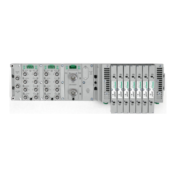
- Page 1 G3 Series PROFIBUS‐DP Technical Manual TDG3PTTM1-2EN 02/09 Subject to change without notice www.numatics.com/g3...
-
Page 2: Table Of Contents
G3 Series PROFIBUS‐DP Technical Manual Table of Contents PAGE About PROFIBUS-DP................................3 Overview ....................................3 G3 PROFIBUS-DP Features ..............................3 Cabling and Drop Line Lengths (as defined by PROFIBUS specification) ..............3 G3 Introduction ..................................4 G3 Electronics Modularity ..............................5 Discrete I/O.................................. 5 Pneumatic Valve Manifold ............................6 Manifold Connectors ................................7 Solenoid Coil Connections using Z-Board Technology for 2005/2012/2035 valve series........ - Page 3 G3 Series PROFIBUS‐DP Technical Manual Analog I/O Module Rules ..............................44 4 Channel I/O - M12 Female Modules ........................44 One Analog Input per Connector - M12 Female Modules ..................45 One Analog I/O per Connector - M12 Female Modules................... 46 I/O Module(s) Wiring Diagrams ............................47 PROFIBUS-DP Configuration and Mapping........................
-
Page 4: About Profibus-Dp
G3 Series PROFIBUS‐DP Technical Manual About PROFIBUS-DP Overview PROFIBUS-DP is a communication protocol used to network industrial devices to eliminate labor intensive and expensive point to point wiring schemes. Siemens originally developed PROFIBUS DP, but it is now supported by a multitude of manufacturers and the protocol standard governed by the PROFIBUS Trade Organization (PTO). -
Page 5: G3 Introduction
This manual details specific information for configuring and commissioning the Numatics G3 Series product line. For more information relating to pneumatic valving and valve manifold assemblies, please refer to the... -
Page 6: G3 Electronics Modularity
G3 Series PROFIBUS‐DP Technical Manual G3 Electronics Modularity Discrete I/O The G3 Series product line is a completely modular and scalable system. As shown below, all of the G3 electronic modules plug together, via mechanical clips, allowing easy assembly and field changes. TDG3PTTM1-2EN 02/09 Subject to change without notice www.numatics.com/g3 Page 5... -
Page 7: Pneumatic Valve Manifold
G3 Series PROFIBUS‐DP Technical Manual Pneumatic Valve Manifold The pneumatic valve manifold with internal circuit board technology is also modular. The valve solenoid coil connections are automatically made using Z-Board technology (plug together PC boards), which allow ™ internal connection from solenoid coils to output drivers without the use of wires). This allows easy assembly and field changes. -
Page 8: Manifold Connectors
G3 Series PROFIBUS‐DP Technical Manual Manifold Connectors Solenoid Coil Connections using Z-Board Technology for 2005/2012/2035 valve series Z-Board plug together technology connects all valve solenoids to the valve coil output driver board, ™ located in the valve adapter. The 32 available coil outputs are divided into 2 separate connector groups. Output group No. -
Page 9: Z-Board™ Connectors
G3 Series PROFIBUS‐DP Technical Manual Z-Board™ Connectors The 2005/2012/2035 valve series utilize 2 different Z-Board ™ designs to achieve the single and double solenoid output functions. This yields the possible 32 single, 16 double, or various combinations of valve coil output capabilities. Single Z-Board Double Z-Board ™... -
Page 10: Z-Board™ And Ribbon Cable Example
G3 Series PROFIBUS‐DP Technical Manual Z-Board™ and Ribbon Cable Example If fourteen (14) single solenoid and one (1) double solenoid valves are connected directly to the communication node via their Z-Boards , and one (1) single solenoid and four (4) double solenoid ™ valves are connected to the communication node via the ribbon cable, the following would be the valve side bit map: Output Word Output Byte... -
Page 11: Z-Board™ With Valve Side Sub-D Example
G3 Series PROFIBUS‐DP Technical Manual Z-Board™ with Valve Side Sub-D Example If sixteen (16) single solenoid valves are connected directly to the communication node via their Z- Boards , and a valve side Sub-D connector is connected to the communication node via the output ™... -
Page 12: Communication Module (Node)
G3 Series PROFIBUS‐DP Technical Manual Communication Module (Node) PROFIBUS-DP Communication Module This module is the communication interface to the manifold. It contains communication electronics and internal short circuit protection for power. It can be configured via software, via the graphic display, or manually via DIP switches through the optional Manual Configuration Module (MCM). The Numatics G3 PROFIBUS-DP node is tested by the PIC to ensure compatibility and interoperability. -
Page 13: Communication Module Description
G3 Series PROFIBUS‐DP Technical Manual Communication Module Description Detail No. Description “Set” Button – used to navigate through user menus and to set parameters Module Status LED 5 Pin M12 Reverse Key Male Communication Connector 5 Pin M12 Reverse Key Female Communication Connector Mounting Hole “Next”... - Page 14 G3 Series PROFIBUS‐DP Technical Manual Connector Pin-Outs Industry standard connectors are used for communication and power. The PROFIBUS-DP communication connectors are a M12 reverse key 5 pin male connector and a M12 reverse key 5 pin female connector. The Power connector is a 7/8” MINI 5 pin male connector. PROFIBUS Communication Connector Pin-Out Pin No.
-
Page 15: Standard Power Connector Wiring Diagram Examples
G3 Series PROFIBUS‐DP Technical Manual Electrical Connections Standard Power Connector Wiring Diagram Examples Single Power Supply Example (Non-isolated commons) Separate Power Supply Example (Isolated commons) Please see page 18 for external fuse sizing guide. When using molded connector power cables, Do Not rely on wire colors for Pin-Out. - Page 16 G3 Series PROFIBUS‐DP Technical Manual Power Consumption Power Connection Pin No. Function Description 0 VDC Common 0 VDC Voltage used to power outputs (valve coils and (Valves and Outputs) discrete outputs) SW 0 VDC Common 0 VDC (-V) Voltage used to power discrete inputs and (Node and Inputs) node electronics UNSW Earth Ground...
-
Page 17: External Fuse Sizing Chart
G3 Series PROFIBUS‐DP Technical Manual Recommended External Fuses External fuses should be chosen based upon the physical manifold configuration. Please refer to table below for the fuse sizing chart. External Fuse Sizing Chart Power Consumption - Power Connector Pin for Valves and Outputs Description Current Number of Solenoid Valve Coils Energized Simultaneously ___ X 0.167 A (ISO - SPA Series) -
Page 18: Communication Module Led Functions
G3 Series PROFIBUS‐DP Technical Manual Diagnostics Communication Module LED Functions Upon power up, the Module and Network Status LEDs indicate the state of the unit. There are two LEDs on the G3 PROFIBUS-DP node. The LEDs functions are described in the table below. LED Name Color Status Description... -
Page 19: G3 Graphic Display
G3 Series PROFIBUS‐DP Technical Manual G3 Graphic Display The G3 Communication and I/O modules have an integrated graphic display that may be used to configure the parameters of the modules as well as showing diagnostic information. The following graphic displays represent the main menu selections of the DeviceNet communication module (node). -
Page 20: Network Address Sub-Menu
G3 Series PROFIBUS‐DP Technical Manual Network Address Sub-Menu Steps to Set Address Press the SET button to enter the ADDRESS sub-menu. ADDRESS Press the NEXT button to scroll through the choices for the hundreds digit of the node address. SET ADDRESS Press the SET button to select the hundreds digit and move into the tens digit selection. -
Page 21: Ssa Lock Sub-Menu
G3 Series PROFIBUS‐DP Technical Manual SSA LOCK Sub-Menu Steps to Set SSA (Set Slave Address) LOCK Press the SET button to enter the SSA Lock sub-menu. SSA LOCK DISABLED Press the NEXT button to enable / disable the SSA Lock SSA LOCK ENABLE ENABLE - allows the address to be set only through the G3 graphic display DISABLE... - Page 22 G3 Series PROFIBUS‐DP Technical Manual Advanced Settings - Brightness Brightness Settings Press the SET button to enter the ADVANCED SETTINGS menu. ADVANCED SETTINGS Press the NEXT button to scroll to the CONFIG MENU / SET BRIGHTNESS. ADVANCED MENU Press the SET button to enter the CONFIG MENU / SET BRIGHTNESS. SET BRIGHTNESS Press the NEXT button to scroll the choices for the desired brightness of the LCD display for all modules on the G3 system.
-
Page 23: Factory Defaults
G3 Series PROFIBUS‐DP Technical Manual Factory Defaults Factory Default Settings Press the SET button to enter the FACTORY DEFAULTS sub-menu. FACTORY DEFAULTS Press the NEXT button to select Yes or No. Selecting No will bring you back to the main FACTORY SET DEFAULTS DEFAULTS menu. Selecting Yes will cause the node to reset and return all parameters to the factory default conditions. -
Page 24: Diagnostics - Self Test Mode
G3 Series PROFIBUS‐DP Technical Manual Diagnostics - Self Test Mode An internal diagnostic tool can be enabled on the communication module (node) using the graphic display. This tool allows the user to confirm that all of the inputs and outputs on the manifold and any of the distributed modules are fully functional without needing a network connection or controller. -
Page 25: Diagnostics Continued
G3 Series PROFIBUS‐DP Technical Manual Diagnostics Continued All diagnostic information is read only DIAGNOSTICS Press the SET button to enter DIAGNOSTICS sub-menu. USNW POWER Press the NEXT button to scroll through the main diagnostic menu choices. 24 VOLTS UNSW POWER - Displays voltage level of unswitched power (Node & Inputs) NETWORK ERRORS - ERROR CODE NETWORK ERRORS - Displays fieldbus network errors... -
Page 26: Error Messages
G3 Series PROFIBUS‐DP Technical Manual Error Messages The following are automatic error messages that are displayed when specific faults occur during operation: Displayed when a short circuit condition is SUB-BUS SHORT detected on the Sub-Bus power lines. Displayed when a short circuit condition is SHORTED COIL detected on a valve coil NO. -
Page 27: Mcm - Manual Configuration Module (Optional)
G3 Series PROFIBUS‐DP Technical Manual MCM – Manual Configuration Module (Optional) The MCM is an optional module that is installed between the node and the valve adapter module and allows the user to manually set, via DIP switches, the node address without the need for software configuration or the use of the integrated graphic display in the node. -
Page 28: Dip Switch Settings
G3 Series PROFIBUS‐DP Technical Manual DIP Switch Settings Shown: Network address = 66 Network Address: Address Value SW-7 SW-6 SW-5 SW-4 SW-3 SW-2 SW-1 (Decimal) TDG3PTTM1-2EN 02/09 Subject to change without notice www.numatics.com/g3 Page 27... -
Page 29: Arm - Auto Recovery Module (Optional)
G3 Series PROFIBUS‐DP Technical Manual ARM – Auto Recovery Module (Optional) The Auto Recovery Module (ARM) is an optional memory module that is installed between the node and the valve adapter module and is used to preserve the manifold configuration settings even during catastrophic failure. During the power-up process it reads the configuration of the manifold, including any user settable parameters of I/O modules, and stores the information in its non volatile memory. -
Page 30: Distribution
G3 Series PROFIBUS‐DP Technical Manual Distribution Distribution of I/O capability can be easily achieved with the G3 platform by means of Sub-Bus modules. I/O modules, valve manifolds and/or a combination of both can be simply separated from the main manifold and distributed via a sub-bus communication cable. The G3 platform uses the same I/O modules on the main manifold as on the distribution chain. -
Page 31: Sub-Bus Distribution Modules
G3 Series PROFIBUS‐DP Technical Manual Sub-Bus Distribution Modules Sub-Bus Out Module Used only when distributing the Sub-Bus to another assembly is required Sub-Bus Out - 5 pin M12 female communication connector. Used to distribute the Sub-Bus to the next Sub-Bus assembly. Carries 24 VDC power for electronics of the next module. ... - Page 32 G3 Series PROFIBUS‐DP Technical Manual Sub-Bus In Modules Used to distribute I/O assemblies that do not have valves Must be installed to the right of the I/O modules Sub-Bus In - 5 pin M12 male communication connector. Must be connected to the Sub-Bus Out connector of the previous assembly Carries 24 VDC power for electronics of module ...
- Page 33 G3 Series PROFIBUS‐DP Technical Manual Terminator Module Used to terminate Sub-Bus connections. Must be installed on the left side of the last Sub-Bus module. Description Part Number Terminator Module with Din Rail Mounting 240-245 Terminator Module without Din Rail Mounting 240-184 The terminator module is required to be installed in the G3 system for proper NOTE! operation TDG3PTTM1-2EN...
-
Page 34: Sub-Bus Valve Module
G3 Series PROFIBUS‐DP Technical Manual Sub-Bus Valve Module COMM - 5 pin M12 male Sub-Bus input communication connector. Must be connected to the Sub-Bus Out connector of the previous assembly Carries 24 VDC power for electronics of module POWER - 4 pin MINI male power connector. Power is required for Outputs ... -
Page 35: Digital I/O Modules
G3 Series PROFIBUS‐DP Technical Manual Digital I/O Modules Digital I/O Module Rules The maximum number of modules that can be used on the Discrete I/O side of the manifold is 16. These modules can be centralized on the main fieldbus manifold, distributed or a combination of both. Modules can be connected in any combination of inputs, outputs and specialty up to the physical limitation of 16 modules. -
Page 36: I/O Module Descriptions & Menus
G3 Series PROFIBUS‐DP Technical Manual I/O Module Descriptions & Menus Detail No. Description “Set” Button – used to navigate through user menus and set parameters Module Function (I/O Type) Alignment arrow for SPEEDCON connector Bit Designation for I/O “Next” Button – used to navigate through user menus and set parameters Graphic Display 5 Pin M12 female I/O connector Connector designation... -
Page 37: Digital Input Modules
G3 Series PROFIBUS‐DP Technical Manual Digital Input Modules One Digital Input per Connector - M12 Female Modules Short Circuit Protection Module Part No. I/O Type Input Points (SCP) 240-210 NPN (Sinking) YES – Visual 240-206 PNP (Sourcing) Input Mapping BYTE Bit 7 Bit 6 Bit 5 Bit 4 Bit 3... -
Page 38: Two Digital Inputs Per Connector - M12 Female Modules
G3 Series PROFIBUS‐DP Technical Manual Two Digital Inputs per Connector - M12 Female Modules Short Circuit Protection Module Part No. I/O Type Input Points (SCP) 240-209 NPN (Sinking) YES – Visual 240-205 PNP (Sourcing) Input Mapping BYTE Bit 7 Bit 6 Bit 5 Bit 4 Bit 3 Bit 2 Bit 1... -
Page 39: Sixteen Digital Inputs - Terminal Strip Modules
G3 Series PROFIBUS‐DP Technical Manual Sixteen Digital Inputs – Terminal Strip Modules Specifications Wire Size Range: 12 to 24 AWG Strip Length: 7mm Terminal Tightening Torque: 0.5 Nm Short Circuit Protection Module Part No. I/O Type Input Points (SCP) 240-203 PNP (Sourcing) YES -Visual 240-204 NPN (Sinking) Input Mapping... -
Page 40: Digital Output Modules
G3 Series PROFIBUS‐DP Technical Manual Digital Output Modules One Digital Output per Connector - M12 Female Modules Short Circuit Protection Module Part No. I/O Type Output Points (SCP) 240-208 PNP (Sourcing) YES – Visual Output Mapping BYTE Bit 7 Bit 6 Bit 5 Bit 4 Bit 3 Bit 2 Bit 1... -
Page 41: Two Digital Outputs Per Connector - M12 Female Modules
G3 Series PROFIBUS‐DP Technical Manual Two Digital Outputs per Connector - M12 Female Modules Short Circuit Protection Module Part No. I/O Type Output Points (SCP) 240-207 PNP (Sourcing) YES – Visual Output Mapping BYTE Bit 7 Bit 6 Bit 5 Bit 4 Bit 3 Bit 2 Bit 1 Bit 0... -
Page 42: Sub-Bus Valve Module
G3 Series PROFIBUS‐DP Technical Manual Sub-Bus Valve Module Used to control a distributed valve manifold through the Sub-Bus. See page 33 for more information. Module I/O Type Short Circuit Protection Output Points Part No. 240-241 NPN (Sinking) YES – Visual Output Mapping BYTE Bit 7 Bit 6 Bit 5 Bit 4... -
Page 43: Digital Input/Output Modules
G3 Series PROFIBUS‐DP Technical Manual Digital Input/Output Modules Two Digital I/O per Connector - M12 Female Modules Short Circuit Output Input Module Part No. I/O Type Protection Points Points 240-211 PNP (Sourcing) YES – Visual Output Mapping BYTE Bit 7 Bit 6 Bit 5 Bit 4 Bit 3 Bit 2... -
Page 44: Valve Side Digital Output Modules
G3 Series PROFIBUS‐DP Technical Manual Valve Side Digital Output Modules The valve side output module is used to distribute available valve side output points via a Sub-D connector (i.e. when a Sub-D valve manifold is located away from the rest of the electronics). This module goes to the right of the G3 valve adapter. -
Page 45: Analog I/O Modules
G3 Series PROFIBUS‐DP Technical Manual Analog I/O Modules Analog I/O Module Rules The analog I/O modules follow the same rules as the digital I/O modules. The maximum total number of modules on the Sub-Bus is 16. The analog modules allow the user to control and/or read analog devices using an analog signal. -
Page 46: One Analog Input Per Connector - M12 Female Modules
G3 Series PROFIBUS‐DP Technical Manual One Analog Input per Connector - M12 Female Modules Module Short Circuit Signal Type Input Points Part No. Protection 240-212 0-10 VDC YES – Visual 240-214 4-20 mA Input Mapping BYTE Bit 7 Bit 6 Bit 5 Bit 4 Bit 3 Bit 2 Bit 1... -
Page 47: One Analog I/O Per Connector - M12 Female Modules
G3 Series PROFIBUS‐DP Technical Manual One Analog I/O per Connector - M12 Female Modules Module Short Circuit Output Signal Type Input Points Part No. Protection Points 240-213 0-10 VDC YES – Visual 240-215 4-20 mA Output Mapping BYTE Bit 7 Bit 6 Bit 5 Bit 4 Bit 3 Bit 2... -
Page 48: I/O Module(S) Wiring Diagrams
G3 Series PROFIBUS‐DP Technical Manual I/O Module(s) Wiring Diagrams NPN/PNP Definitions There is confusion between NPN, PNP, Sinking and Sourcing terminologies. Basically, if one is using sensors that provide a 24 VDC signal to the input module then a PNP input module type will be required. If one is using a sensor that supplies a 0 VDC signal to the input module then an NPN input module type will be required. - Page 49 G3 Series PROFIBUS‐DP Technical Manual I/O Module(s) Wiring Diagrams Continued PNP (Sourcing) Output Connection TDG3PTTM1-2EN 02/09 Subject to change without notice www.numatics.com/g3 Page 48...
-
Page 50: Profibus-Dp Configuration And Mapping
G3 Series PROFIBUS‐DP Technical Manual PROFIBUS-DP Configuration and Mapping GSD File The GSD file contains configuration information required to establish communication to a node on a PROFIBUS-DP network. The GSD file is available on the Numatics, Inc., website at www.numatics.com/fieldbus. TDG3PTTM1-2EN 02/09 Subject to change without notice www.numatics.com/g3 Page 49... -
Page 51: User Configurable Device Parameters
G3 Series PROFIBUS‐DP Technical Manual User Configurable Device Parameters The Numatics’ G3 PROFIBUS-DP node allows the user to set many user options which define how the manifold behaves in certain instances. The following are descriptions of these device parameters. Settable Via Parameter Name Description Display Software √... -
Page 52: Communication Fault/Idle Mode Parameter
G3 Series PROFIBUS‐DP Technical Manual Communication Fault/Idle Mode Parameter This parameter is used to set the behaviors of output points (bits) during a communication fault or an “idle” event (when a PLC is “Idle mode” not in RUN mode). The parameter shown below is used to determine what state the outputs will have during an “Idle”... -
Page 53: Profibus-Dp Mapping
G3 Series PROFIBUS‐DP Technical Manual PROFIBUS-DP Mapping I/O Sizes Outputs Outputs are defined as any valve solenoid coil and/or any discrete output point from any output module. The output size depends upon the physical configuration of the manifold (i.e. module type and how many are used). Please reference the following pages for a detailed explanation for calculating the output size. -
Page 54: Manifold And I/O Data Sizing Worksheet
G3 Series PROFIBUS‐DP Technical Manual Manifold and I/O Data Sizing Worksheet Step : Choose corresponding Input and Output values based on the chosen “ Valve Side Output Options” and place the values in the boxes labeled, “Valve Side Byte Requirements” at the bottom of the page : Choose up to sixteen modules to be included on the discrete I/O side of the manifold (including distributed modules) and place sum of the corresponding input bytes and output bytes in the boxes labeled, “Discrete Side Byte Requirements”... -
Page 55: Valve Side
G3 Series PROFIBUS‐DP Technical Manual Bit Mapping Rules The bit mapping for a G3 manifold varies with the physical configuration of the manifold. The following is a breakdown of the bit mapping rules associated with the Numatics valve manifold. Valve Side 1) Solenoid coil outputs are connected to the valve coils using the Z-Boards ™... -
Page 56: Example No. 1
G3 Series PROFIBUS‐DP Technical Manual I/O Mapping Examples Example No. 1 Assumed Settings - Double Z-Boards used with all valves - I/O Modules and mapping schemes are identified by their corresponding color. - 32 coils are allocated Manifold I/O Configuration Module Type Part No. Bytes 1 ... - Page 57 G3 Series PROFIBUS‐DP Technical Manual Example No. 1 Table Output Table BYTE Bit 7 Bit 6 Bit 5 Bit 4 Bit 3 Bit 2 Bit 1 Bit 0 Valve Coil Valve Coil Valve Coil Valve Coil Valve Coil Valve Coil Valve Coil Valve Coil No.
-
Page 58: Example No. 2
G3 Series PROFIBUS‐DP Technical Manual Example No. 2 Assumed Settings Double Z-Boards used with all valves I/O Modules and mapping schemes are identified by their corresponding color. 32 coils are allocated. Manifold I/O Configuration Pos. Module Type Part No. Bytes Valve Coil Local Valve Size: 0 4 Number ... - Page 59 G3 Series PROFIBUS‐DP Technical Manual Example No. 2 Table Output Table BYTE Bit 7 Bit 6 Bit 5 Bit 4 Bit 3 Bit 2 Bit 1 Bit 0 Valve Coil Valve Coil Valve Coil Valve Coil Valve Coil Valve Coil Valve Coil Valve Coil No.
-
Page 60: Example No. 3
G3 Series PROFIBUS‐DP Technical Manual Example No. 3 Assumed Settings - Double Z-Boards used with all valves - I/O Modules and mapping schemes are identified by their corresponding color. - 32 coils are allocated Manifold I/O Configuration Module Type Part No. Bytes 1 16I PNP 240‐205 ... - Page 61 G3 Series PROFIBUS‐DP Technical Manual Example No. 3 Table Output Table BYTE Bit 7 Bit 6 Bit 5 Bit 4 Bit 3 Bit 2 Bit 1 Bit 0 Valve Coil Valve Coil Valve Coil Valve Coil Valve Coil Valve Coil Valve Coil Valve Coil No.
-
Page 62: Example No. 4
G3 Series PROFIBUS‐DP Technical Manual Example No. 4 Assumed Settings - Double Z-Boards used with all valves - I/O Modules and mapping schemes are identified by their corresponding color. - 32 coils are allocated Manifold I/O Configuration Module Type Part No. Bytes 1 16I PNP 240‐205 ... - Page 63 G3 Series PROFIBUS‐DP Technical Manual Example No. 4 Table Output Table BYTE Bit 7 Bit 6 Bit 5 Bit 4 Bit 3 Bit 2 Bit 1 Bit 0 Valve Coil Valve Coil Valve Coil Valve Coil Valve Coil Valve Coil Valve Coil Valve Coil No.
-
Page 64: Example No. 5
G3 Series PROFIBUS‐DP Technical Manual Example No. 5 Assumed Settings - Double Z-Boards used with all valves - I/O Modules and mapping schemes are identified by their corresponding color. - 32 coils are allocated 0 Manifold I/O Configuration 1 2 3 Module Type Part No. 5 ... - Page 65 G3 Series PROFIBUS‐DP Technical Manual Example No. 5 Table Output Table BYTE Bit 7 Bit 6 Bit 5 Bit 4 Bit 3 Bit 2 Bit 1 Bit 0 Valve Coil Valve Coil Valve Coil Valve Coil Valve Coil Valve Coil Valve Coil Valve Coil No.
-
Page 66: Extended Diagnostics
G3 Series PROFIBUS‐DP Technical Manual Extended Diagnostics Data Diagnostic Telegram Example data structure (Hexadecimal): Byte 0 Byte 1 Byte 2 Byte 3 Byte 4 Byte 5 Byte 6 Byte 7 Byte 8 Byte 9 Byte 0 Total number of bytes in telegram determined by physical configuration Byte 1 Diagnostic Word, byte 0 (see below) Byte 2... - Page 67 G3 Series PROFIBUS‐DP Technical Manual Diagnostic Telegram Example Diagnostic Telegram Data for above manifold (Hexadecimal) Total number of bytes in telegram Diagnostic Word, byte 0 (00000000) Diagnostic Word, byte 1 (00000000) First diagnostic byte of valve driver module. (01010100) Second diagnostic byte of valve driver module. (11110000) Third diagnostic byte of valve driver module.
-
Page 68: Appendix
G3 Series PROFIBUS‐DP Technical Manual Appendix System Specifications Electrical Valves (2005, 2012, 2035): 24 VDC + 10%, -15% Supply Voltage Node and Discrete I/O: 24 VDC ± 10% Total current on the Auxiliary Power Connector (“Valves and Outputs” and Current “Node and Inputs” Pins) must not exceed 8 Amps. Internal Electronic The Power Connector pins are each internally fused with an electronically resettable Resettable... -
Page 69: Factory Default Settings
G3 Series PROFIBUS‐DP Technical Manual Factory Default Settings FACTORY DEFAULT SETTINGS Description Default Node Address SSA Lock Disabled Brightness High Troubleshooting Communication Node Symptom Possible Cause Solution Check that correct Z-Board types are Z-Board type mismatch. The wrong valve solenoid installed. Check that ribbon cable Single Z-Board present coils are being energized. -
Page 70: Glossary Of Terms
G3 Series PROFIBUS‐DP Technical Manual Glossary of Terms The following is a list and description of common terms and symbols used throughout this document: Term Description A technology that enables the communication node to automatically set its own baud rate to match the DeviceNet scanners’ Auto-Baud baud rate. -
Page 71: Technical Support
G3 Series PROFIBUS‐DP Technical Manual Technical Support For technical support, contact your local Numatics distributor. If further information is required, please call Numatics Inc. Technical Support Department at (248) 596-3333. Issues relating to network setup, PLC programming, sequencing, software related functions, etc. should be handled with the appropriate product vendor.