Table of Contents
HP Moonshot-45XGc Switch
User and Maintenance Guide
Abstract
This document is for the person who installs, administers, services, and troubleshoots switches. This guide provides identification, setup, installation,
and removal procedures. HP assumes you are qualified in these areas.
Part Number: 796044-001
September 2014
Edition: 1
Table of Contents

Related Manuals for HP Moonshot-45XGc


Summary of Contents for HP Moonshot-45XGc
- Page 1 User and Maintenance Guide Abstract This document is for the person who installs, administers, services, and troubleshoots switches. This guide provides identification, setup, installation, and removal procedures. HP assumes you are qualified in these areas. Part Number: 796044-001 September 2014...
- Page 2 © Copyright 2014 Hewlett-Packard Development Company, L.P. The information contained herein is subject to change without notice. The only warranties for HP products and services are set forth in the express warranty statements accompanying such products and services. Nothing herein should be construed as constituting an additional warranty. HP shall...
-
Page 3: Table Of Contents
Network mapping ........................26 Production network mapping ........................26 Management network mapping ........................27 Interfaces ..............................27 Moonshot-4QSFP+ uplink interfaces ....................28 Moonshot-45XGc downlink interfaces ....................29 Troubleshooting .......................... 30 Troubleshooting resources ........................... 30 Illustrated parts catalog ....................... 31 Contents 3... - Page 4 Specifications ..........................37 Chassis environmental specifications ......................37 Chassis specifications ..........................37 Support and other resources ......................38 Before you contact HP ..........................38 HP contact information ..........................38 Acronyms and abbreviations ......................39 Documentation feedback ......................41 Index ............................42...
-
Page 5: Component And Led Identification
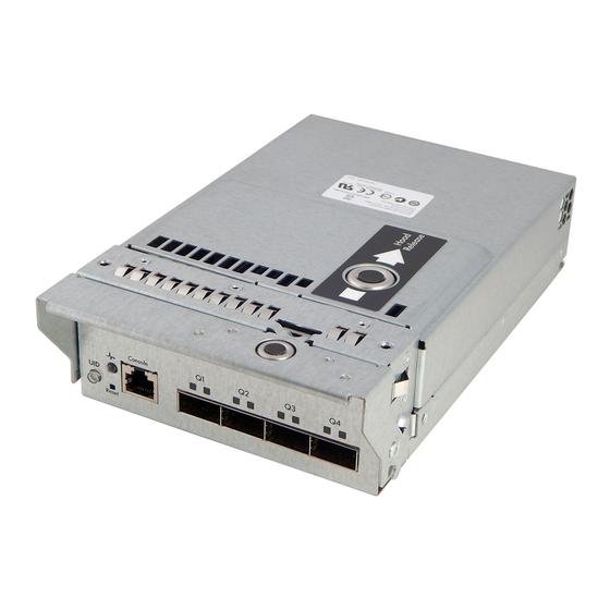
Component and LED identification Chassis front panel LEDs and buttons Item Description LED Status Chassis power LED Flashing green = The chassis is waiting to power on. Green = Normal operation Amber = Standby operation Off = No power Chassis health LED Green = Normal operation Flashing amber = Degraded condition Flashing red = Critical condition... -
Page 6: Moonshot-4Qsfp Uplink Module Components
• HP QSFP+ to SFP+ Adapter Use any available port to connect to the data center. Be sure the port is populated with a supported HP transceiver module that is compatible with the data center switch port type. Component and LED identification 6... -
Page 7: Moonshot-4Qsfp Uplink Module Buttons And Leds
Moonshot-4QSFP uplink module buttons and LEDs Item Description Status Uplink module UID Solid blue = Switch module ID is selected. LED/button Flashing blue = Switch module firmware update is in progress. Off = Switch module ID is not selected. Uplink module health Green = Normal operation Flashing amber = Degraded condition Flashing red = Critical condition... -
Page 8: Moonshot Switch Module Leds
Moonshot switch module LEDs Item Description Status Switch module power Green = Normal operation Amber = Standby operation Off = No power Switch module health Green = Normal operation Flashing amber = Degraded condition Flashing red = Critical condition Off = No power Switch module uplink Green = Link activity LED... -
Page 9: Operations
Operations Extend the chassis from the rack Pull down the quick release levers on each side of the chassis. WARNING: To reduce the risk of personal injury or equipment damage, be sure that the rack is adequately stabilized before extending a component from the rack. Extend the chassis from the rack until it locks once. -
Page 10: Remove The Access Panel
After performing the installation or maintenance procedure, slide the chassis back into the rack, and then press the chassis firmly into the rack to secure it in place. Remove the access panel IMPORTANT: After performing a procedure inside the chassis, always install the access panel on the chassis when complete. -
Page 11: Open The Cable Management Arm
Lift and remove the access panel. Turn the access panel over to locate the HP Moonshot 1500 Chassis label. This label provides information on LED status indicators, component identification, and chassis and switch installation procedures. Open the cable management arm To open the cable management arm, lift it up as you swing it open. -
Page 12: Remove The Uplink Module Blank
Remove the uplink module blank Remove the component as indicated. Remove the switch module blank Remove the component as indicated. Operations 12... -
Page 13: Setup
Removing any component from bay A or bay B does not disrupt traffic for the other switch. • Always use the recommended firmware version. For current information on recommended firmware versions, see the HP website (http://www.hp.com/go/moonshot/download). • For the most current product information, see the HP Moonshot Information Library (http://www.hp.com/go/moonshot/docs). Setup 13... -
Page 14: Uplink Module Bays
Uplink module bays The uplink module can be installed in the uplink module bays located in the rear of the chassis. Installing the uplink module IMPORTANT: To avoid connectivity loss, do not remove any network cables or uplink modules already in operation. Remove the uplink module bay blank. -
Page 15: Installing The Switch Module
For more information, see the "Installation information and guidelines (on page 13)." After both components have been installed, verify the switch firmware is at the recommended firmware version. For more information, see the HP website (http://www.hp.com/go/moonshot/download). The installation is complete. - Page 16 Locate the switch module slot and remove the blank. Prepare the switch module for installation. Setup 16...
- Page 17 For more information, see "Installation information and guidelines (on page 13)." Install the access panel. Install the chassis in the rack. After both components have been installed, verify the switch firmware is at the recommended firmware version (http://www.hp.com/go/moonshot/download). The installation is complete. Setup 17...
-
Page 18: Cabling
Cabling Supported cables and transceivers The following cables and transceiver modules are supported for the HP Moonshot-4QSFP+ Uplink Module: • HP 40GBASE QSFP+ DAC • HP 40GBASE QSFP+ to 4x10G SFP+ • HP 40GBASE QSFP+ SR4 • HP 40GBASE QSFP+ •... -
Page 19: Installing A Transceiver
To install a transceiver or transceiver adapter: IMPORTANT: Use only HP approved transceivers. Verify the transceiver type by checking the label. Remove the dust plug from the correct port. - Page 20 Transceiver adapter If a cable needs to be connected, remove any dust plugs or covers, and then connect the cable. Cabling 20...
-
Page 21: Command Line Interface
Command Line Interface Connecting to the switch console To connect to the switch console, use one of the following methods: • To connect locally, use the serial console port ("Accessing the CLI locally" on page 21). • To connect remotely, be sure the management network is connected to the iLO CM management port ("Accessing the CLI remotely"... -
Page 22: Accessing The Cli Remotely
Configure a static management IP address or use DHCP services to assign a management IP address. • Configure access authentication methods. To see configuration procedures, see the HP Moonshot-45XGc Switch Fundamentals Configuration Guide in the HP Moonshot Switch Library (http://www.hp.com/go/moonshot/XGcSwitch). Accessing the CLI using iLO... - Page 23 {off|on} {sa|sb|sa-b} set switch uid {off|on} {sa|sb|sa-b} For more information on the iLO CM firmware, see the latest HP Moonshot iLO Chassis Management CLI User Guide in the HP Moonshot Information Library (http://www.hp.com/go/moonshot/docs). Command Line Interface 23...
-
Page 24: Configuration
Configuration Switch documentation To configure the switch, see the switch configuration guides in the HP Moonshot Switch Information Library (http://www.hp.com/go/moonshot/XGcSwitch). Configuration 24... -
Page 25: Firmware
Firmware Update the switch firmware Before updating switch firmware, see the "Upgrading software" section of the HP Moonshot-45XGc Fundamentals Configuration Guide in the HP Moonshot Switch Information Library (http://www.hp.com/go/moonshot/XGcSwitch). You can download firmware updates from the HP Moonshot Component Pack download site (http://www.hp.com/go/moonshot/download). -
Page 26: Network Mapping
Network mapping Production network mapping The first network interface discovered by the operating system routes traffic through switch A. The second network interface discovered by the operating system routes traffic through switch B. Network mapping 26... -
Page 27: Management Network Mapping
External ports are located on slot 1. • The port identifies the specific physical port or logical interface being managed on a given slot. To learn more, see switch documentation in the HP Moonshot Networking Library (http://www.hp.com/go/moonshot/networking). Network mapping 27... -
Page 28: Moonshot-4Qsfp+ Uplink Interfaces
Moonshot-4QSFP+ uplink interfaces Item Port Port speed Interface 40Gb fortygige1/1/1 10Gb ten-gigabitethernet1/1/1:1–4 40Gb fortygige1/1/2 10Gb ten-gigabitethernet1/1/2:1–4 40Gb fortygige1/1/3 10Gb ten-gigabitethernet1/1/3:1–4 40Gb fortygige1/1/4 10Gb ten-gigabitethernet1/1/4:1–4 Network mapping 28... -
Page 29: Moonshot-45Xgc Downlink Interfaces
Moonshot-45XGc downlink interfaces Interfaces 1/0/1–1/0/45 are the downlinks to the cartridge nodes. Each SoC is identified as a cartridge node. The iLO CM firmware identifies each node as cxny, where c is the cartridge and n is the node. Switch interfaces correspond to cartridge nodes, respectively. For example, c28n1 corresponds to cartridge 28, node 1, and interface 1/0/28. -
Page 30: Troubleshooting
The HP Moonshot System Troubleshooting Guide provides procedures for resolving common problems and comprehensive courses of action for fault isolation and identification, issue resolution, and software maintenance on the HP Moonshot System. The document is available in the HP Moonshot Information Library (http://www.hp.com/go/moonshot/docs). -
Page 31: Illustrated Parts Catalog
HP specifies in the materials shipped with a replacement CSR part whether a defective part must be returned to HP. In cases where it is required to return the defective part to HP, you must ship the defective part back to HP within a defined period of time, normally five (5) business days. The defective part must be returned with the associated documentation in the provided shipping material. -
Page 32: Switch Customer Self Repair Components
Optional—Parts for which customer self repair is optional. These parts are also designed for customer self repair. If, however, you require that HP replace them for you, there may or may not be additional charges, depending on the type of warranty service designated for your product. -
Page 33: Removal And Replacement Procedures
Removal and replacement procedures Removing the switch module CAUTION: Be sure to save the running-configuration of the switch before removing any switch components. CAUTION: To avoid connectivity loss, do not remove switches already in operation. CAUTION: For proper cooling, be sure every switch module bay and uplink module bay has either a blank or a module installed. - Page 34 CAUTION: For proper cooling, be sure every switch module bay and uplink module bay has either a blank or a module installed. Open the cable management arm (on page 11). Remove the component as indicated. Removal and replacement procedures 34...
-
Page 35: Regulatory Information
Regulatory information Safety and regulatory compliance For safety, environmental, and regulatory information, see Safety and Compliance Information for Server, Storage, Power, Networking, and Rack Products, available at the HP website (http://www.hp.com/support/Safety-Compliance-EnterpriseProducts). Turkey RoHS material content declaration Ukraine RoHS material content declaration Warranty information HP ProLiant and X86 Servers and Options (http://www.hp.com/support/ProLiantServers-Warranties) -
Page 36: Electrostatic Discharge
Electrostatic discharge Preventing electrostatic discharge To prevent damaging the system, be aware of the precautions you need to follow when setting up the system or handling parts. A discharge of static electricity from a finger or other conductor may damage system boards or other static-sensitive devices. -
Page 37: Specifications
Specifications Chassis environmental specifications Specification Value — Temperature range* 10°C to 35°C (50°F to 95°F) Operating -30°C to 60°C (-22°F to Non-operating 140°F) — Maximum Wet bulb temperature 28ºC (82.4ºF) Operating 38.7ºC (101.7ºF) Non-operating Relative humidity (non-condensing)** — 10% to 90% Operating 5% to 95% Non-operating... -
Page 38: Support And Other Resources
Operating system type and revision level To obtain product information, log in to iLO CM firmware and use the Show Chassis Info command. For more information, see the HP Moonshot iLO Chassis Management CLI User Guide in the HP Moonshot Information Library (http://www.hp.com/go/moonshot/docs). -
Page 39: Acronyms And Abbreviations
Acronyms and abbreviations chassis management HP Insight Cluster Management Utility Customer Self Repair direct attach cable DHCP Dynamic Host Configuration Protocol electrostatic discharge identification Media Access Control QSFP quad small form-factor pluggable QSFP+ enhanced quad small form-factor pluggable Secure Copy Protocol... - Page 40 SFTP Secure File Transfer Protocol system on chip short range Secure Shell TFTP Trivial File Transfer Protocol unit identification virtual serial port Acronyms and abbreviations 40...
-
Page 41: Documentation Feedback
Documentation feedback HP is committed to providing documentation that meets your needs. To help us improve the documentation, send any errors, suggestions, or comments to Documentation Feedback (mailto:[email protected]). Include the document title and part number, version number, or the URL when submitting your feedback. -
Page 42: Index
HP contact information 38 administration 24 HP technical support 38 authorized reseller 38 illustrated parts catalog 31 before you contact HP 38 installation 14, 15 blank, removal 12 installing modules 14, 15 interface 27, 28, 29 cable management arm 11... - Page 43 38 troubleshooting 30 updating firmware 25 uplink module 14 uplink module bay identification 13, 14 uplink module, installing 14 uplink module, removing 33 warranty 31, 35 website, HP 38 Index 43...