GE CARESCAPE Monitor B850 Technical Manual
Hide thumbs
Also See for CARESCAPE Monitor B850:
- Supplement manual (72 pages) ,
- Service manual (192 pages)

Related Manuals for GE CARESCAPE Monitor B850


Summary of Contents for GE CARESCAPE Monitor B850
- Page 1 GE Healthcare CARESCAPE™ Monitor B850 Technical Manual Software Version 1 CARESCAPE™ Monitor B850 English 2040387-004 (CD) 2040386-004D (paper) © 2009, 2011 General Electric Company All rights reserved.
- Page 2 NOTE: The information in this manual applies to CARESCAPE B850 monitors. NOTE: For technical documentation purposes, the abbreviation GE is used for the legal entity name, GE Medical Systems Information Technologies and GE Healthcare Finland Oy. Listed below are GE Medical Systems Information Technologies and GE Healthcare Finland Oy trademarks used in this document.
- Page 3 Part I, System installation Description Introduction System overview Hardware installation Configuration Installation checkout Part II, Repair and maintenance Description Patient monitor repair overview Maintenance and checkout Troubleshooting Disassembly and reassembly Service parts 2040384-004D CARESCAPE Monitor B850...
- Page 4 Appendices Description Appendix A Electromagnetic compatibility Appendix B Check form CARESCAPE Monitor B850 2040384-004D...
- Page 5 Device plate location ......... . 1-20 2040384-004D CARESCAPE Monitor B850...
- Page 6 Frame and E-Modules .........3-13 CARESCAPE Monitor B850...
- Page 7 ECG filter configuration ........4-23 2040384-004D CARESCAPE Monitor B850...
- Page 8 Keyboard ...........5-16 CARESCAPE Monitor B850...
- Page 9 Auxiliary devices ..........7-5 2040384-004D CARESCAPE Monitor B850...
- Page 10 Recommended checkout ......... . .9-20 viii CARESCAPE Monitor B850 2040384-004D...
- Page 11 Check form ............B-3 2040384-004D CARESCAPE Monitor B850...
- Page 12 CARESCAPE Monitor B850 2040384-004D...
-
Page 13: Introduction
Introduction 2040384-004D CARESCAPE Monitor B850... -
Page 14: Manual Information
It can also be connected to other monitors for bed to bed viewing and to data management software devices via a network. The CARESCAPE Monitor B850 is intended for use under the direct supervision of a licensed healthcare practitioner, or by personnel trained in proper use of the equipment in a professional healthcare facility. -
Page 15: Manual Purpose
This manual is intended for service representatives and technical personnel who install, maintain, troubleshoot, or repair this equipment. Ordering manuals A paper copy of this manual will be provided upon request. Contact your local GE representative and request the part number on the first page of the manual. Related documents... -
Page 16: Conventions Used In This Manual
Messages (alarm messages, informative messages) displayed on the screen are written inside single quotes: ‘Learning’ Note statements provide application tips or other useful information. Product references In this manual, the CARESCAPE Monitor B850 is referred to as the patient monitor. CARESCAPE Monitor B850 2040384-004D... -
Page 17: Safety Information
Safety information Responsibility of the manufacturer GE is responsible for the effects of safety, reliability, and performance only if: Assembly operations, extensions, readjustments, modifications, or repairs are carried out by persons authorized by GE. The electrical installation of the relevant room complies with the requirements of the appropriate regulations. -
Page 21: Maintenance Schedule
Chinese standard SJ/T11363-2006, and can be recycled after being discarded, and should not be casually discarded. 2040384-004D CARESCAPE Monitor B850 1-15... -
Page 22: Safety Symbols
Type BF (IEC 60601-1) protection against electric shock. Isolated (floating) applied part suitable for intentional external and internal application to the patient, excluding direct cardiac application. 1-16 CARESCAPE Monitor B850 2040384-004D... - Page 23 BIS and Entropy sensor impedance check indicator. Displays for each sensor as the impedance check is in progress. BIS and Entropy sensor impedance check error indicator. Indicates the specified sensor failed the impedance check. 2040384-004D CARESCAPE Monitor B850 1-17...
- Page 24 Reminder volume icon. Adjust the volume of the tone that sounds every two minutes when audio alarms are turned off. Respiration indicator. Indicates a breath is detected by the impedance respiration algorithm. 1-18 CARESCAPE Monitor B850 2040384-004D...
- Page 25 Any unauthorized attempt to repair equipment under warranty voids that warranty. It is the user’s responsibility to report the need for service to GE or to one of their authorized agents. Failure on the part of the responsible individual, hospital, or institution using this equipment to implement a satisfactory maintenance schedule may cause undue equipment failure and possible health hazards.
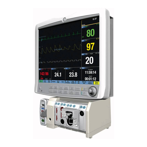
- Page 27 19-inch touch LCD with integrated keypads. Both displays include an integrated alarm light. 15-inch non-touch LCD 19-inch touch LCD Refer to the “CARESCAPE Monitor B850 Addendum for Device Compatibility” for a list of compatible devices. Input devices Input devices include remote control, keypad, keyboard, mouse and barcode reader.
- Page 28 Refer to the “CARESCAPE Monitor B850 Addendum for Device Compatibility” for a list of compatible devices. Module Frames and Tram-Rac housing F5 and F7 Module Frames provide an interface between the patient monitor and E- Modules. The F5 Module Frame has 5 module slots that support a series of E-module acquisition devices.
- Page 30 2-10 CARESCAPE Monitor B850 2040384-004D...
-
Page 31: Hardware Installation
Hardware installation 2040384-004D CARESCAPE Monitor B850... -
Page 32: Installation Requirements
For information about the operating environment for the patient monitor, refer to “Intended use” on page 1-2. Check the “CARESCAPE Monitor B850 Technical Specifications Supplement” for power, temperature and operating conditions requirements. Pre-installation Make sure the following is in place before installing the patient monitoring system hardware. -
Page 33: Mounting
For details about the available mounting solutions, refer to the Mounting Reference Guide. NOTE The GE logo can be rotated for vertical mounting configurations. Rotating GE logo Water shield For vertical mounting configurations, a water shield is available. The water shield lowers the probability of the ingress of fluids into the assembly. -
Page 34: System Components
(electrically isolated RS232 interface). WARNING Do not under any circumstances remove the grounding conductor from the power plug. Always check that power cord and plug are intact and undamaged. CARESCAPE Monitor B850 2040384-004D... -
Page 35: Displays
(1 and 2) connection The following connectors are available for system components: Four USB ports Two Ethernet network ports Two serial RS232 ports Two video display ports (a third optional port may also be available) Two ePort/Tramnet ports 2040384-004D CARESCAPE Monitor B850... -
Page 36: Usb And Serial Port Management
DVI-I 1 and DVI-I 3 ports. Cloned displays must be connected using a DVI-I to DVI-D and VGA splitter and must support analog video. Refer to the “CARESCAPE Monitor B850 Addendum for Device Compatibility” for a list of compatible devices. -
Page 37
If the displays contain a touchscreen, calibrate as follows: Select Monitor Setup > Service Calibrations. Log in with your service username and password and press Enter. Username: biomed Password: Change
Me NOTE Username and password are case sensitive. 2040384-004D CARESCAPE Monitor B850... - Page 38 If the third video card is licensed, configure it. Follow these steps: Go to Monitor Setup > Default Setup > Care Unit Settings > Screens. Under Show Applications, click on Screen 3. Restart the patient monitor. CARESCAPE Monitor B850 2040384-004D...
-
Page 39: Communication
“Setup instructions” on page 3-10 for instructions on setting up the remote display as shown in the example. NOTE Only the display interface connections (video and USB connections) are shown. Not all other connections are shown. 2040384-004D CARESCAPE Monitor B850... - Page 40 Connect the Type A plug of the second USB extender to the Type A receptacle on the first USB extender. Connect the Type A plug of the standard USB cable to the Type A receptacle on the second USB extender. 3-10 CARESCAPE Monitor B850 2040384-004D...
-
Page 41: Non-Medical Grade Displays
Connect a USB keyboard, mouse, remote, or barcode scanner to available USB ports. Connect the following interface devices to an M-Port on the front panel: Unity Network ID connectivity device PRN 50-M keypad M-Ports M1 - M4 2040384-004D CARESCAPE Monitor B850 3-11... -
Page 42: Networks
IEC/EN 60601-1-1 in order to meet system leakage current requirements. NOTE Refer to the “CARESCAPE Monitor B850 Addendum for Device Compatibility” for compatible CARESCAPE Network and S/5 Network devices. Connect the MC Network or S/5 Network cable to the CARESCAPE Network MC port on the device. -
Page 43: Frame And E-Modules
The ePort and Tramnet ports allow connection of E-Module Frame, Tram-Rac housing and PDM. Configuration options See the following table for possible configuration options. For detailed information on compatibility, refer to the “CARESCAPE Monitor B850 Addendum for Device Compatibility.” ePort 1/Tramnet 1 connected devices Tram-Rac... - Page 44 You can also remove both modules and re-connect the new module after five seconds. Refer to the “CARESCAPE Monitor B850 Addendum for Device Compatibility” for a list of compatible devices. NOTE To ensure proper grounding of the Frame, secure the cable connections by using a screwdriver to fully seat all thumbscrews.
- Page 45 You can also remove both modules and re-connect the new module after five seconds. Refer to the “CARESCAPE Monitor B850 Addendum for Device Compatibility” for a list of compatible devices. 2040384-004D...
- Page 46 You can also remove both modules and re-connect the new module after five seconds. Refer to the “CARESCAPE Monitor B850 Addendum for Device Compatibility” for a list of compatible devices. With the module properly oriented, align the module insertion guide slot with the insertion guide.
- Page 47 The PDM module can be connected directly to the patient monitor or it can be mounted to F5 Frame insertion guides. NOTE PDM software v1.2 is required for use with CARESCAPE Monitor B850 software. The PDM can not be installed to an F7 Frame.
-
Page 48: Tram-Rac Housing And Modules
Push the module into the frame until it stops. NOTE An error message displays if an incompatible module is connected. Refer to the “CARESCAPE Monitor B850 Addendum for Device Compatibility” for details. Tram-Rac housing and modules The patient monitor provides support to connect multiple parameter modules at a time. - Page 49 Configuration options See the following table for possible configuration options. For detailed information on compatibility, refer to the “CARESCAPE Monitor B850 Addendum for Device Compatibility.” ePort 1/Tramnet 1 connected devices Tram-Rac Tram-Rac housing housing (AC Mains Frame Frame powered) Tram-Rac...
- Page 50 A TRAM module must always occupy the top position in the Tram-Rac housing. Other modules are installed below it. When using more than one Tram-Rac housing, one of the Tram-Racs must have a power supply. Make sure the Tram-Net cable has ferrite blocks on both ends. 3-20 CARESCAPE Monitor B850 2040384-004D...
- Page 51 NOTE An error message displays if an incompatible module is connected. Refer to the “CARESCAPE Monitor B850 Addendum for Device Compatibility” for details. Face the Tram-Rac housing and guide the back of the module into the appropriate position.
-
Page 53: Using A Service Pc Over The Network
Verify that the service PC is able to perform a network ping to the patient monitor. See “Ping a TCP/IP network device” on page 8-5. Connect a correctly configured service laptop to the CARESCAPE Network IX connection port on the patient monitor using a crossover cable. 2040384-004D CARESCAPE Monitor B850... - Page 55 CARESCAPE Monitor B850 2040384-004D...
-
Page 57: Log Into Webmin
4-4 and select the Configuration tab. On the Configuration tab, select Admit Settings. On the Sub-Modules for Admit Settings menu, select Barcode Settings. Under Barcode Setup on the Barcode Settings window, select the applicable 4-14 CARESCAPE Monitor B850 2040384-004D... - Page 58 (from 1 to 300). In the Length column, type the number of characters (from 1 to 99) that the field contains. For Gender Format, select Fixed or Configured. If you select Configured: Type the character that identifies Male. 2040384-004D CARESCAPE Monitor B850 4-15...
- Page 59 10 items. The following table lists the starting position and length of each item Item Starting Position Length First Name Last Name Day of Birth Month of Birth Year of Birth Age Unit Gender Height 4-16 CARESCAPE Monitor B850 2040384-004D...
- Page 60 Use incremental numbers from 1 (the left-most field) up to 16 (the right-most field). If an item is not included in the barcode, leave the Position field blank for the item. 2040384-004D CARESCAPE Monitor B850 4-17...
- Page 61 12 items and uses the pound sign (#) as a delimiter. Item Sequence number of the item in the barcode First Name Last Name Day of Birth Month of Birth Year of Birth Age Unit Gender Height 4-18 CARESCAPE Monitor B850 2040384-004D...
- Page 62 Admit/Discharge menu. If a field contains a forbidden character, that character will be replaced with a space when it is displayed on the Admit/Discharge menu. 2040384-004D CARESCAPE Monitor B850 4-19...
- Page 63 ! " # ¤ % & /( ) = ? ` @ £ $ € { [ ] } \ * ^ _ : ; | < > Referring Physician 4-20 CARESCAPE Monitor B850 2040384-004D...
- Page 64 The language takes effect after the patient monitor is restarted. National requirements Select the national requirements for the system. If you have not already done so, “Log into Webmin” on page 4-4 and select the Configuration tab. On the Configuration tab, select National Requirements. 2040384-004D CARESCAPE Monitor B850 4-21...
- Page 65 Configuration tab. On the Configuration tab, select Modules. On the Sub-Modules for Modules menu, select Assets Settings. On the Assets Settings window, enter the user-assigned asset number for the device in the Change Value to column. 4-22 CARESCAPE Monitor B850 2040384-004D...
- Page 66 On the Sub-Modules for Modules menu, select ECG Filter Configuration. On the ECG Filter Configuration window, select the applicable radio button to Enable or Disable the line frequency filter. Select Submit. The change will take effect immediately. 2040384-004D CARESCAPE Monitor B850 4-23...
- Page 67 Failure to limit access of Webmin to trained and authorized personnel only may compromise patient safety and/or system performance. If you have not already done so, “Log into Webmin” on page 4-4 and select the Configuration tab. On the Configuration tab, select Passwords. 4-24 CARESCAPE Monitor B850 2040384-004D...
- Page 68 Password is required. Otherwise, select None. Remote Service Configuration Item Description Comments System ID Identifies the system to the GE backoffice servers. These values are read-only and are unique. Serial Number Identifies the unit and is set at the time of manufacture.
- Page 69 Remote Service Configuration Item Description Comments Enterprise URL If required, designate the address of the GE backoffice servers required to communicate with the This address should never Remote Service Agent. be changed unless explicit instructions are given to do Enterprise Tunnel...
-
Page 70: Network
On the Configuration tab, select Settings. On the Sub-Modules for Settings menu, select Save. On the Save Settings window, select the radio button next to the type of settings you want to save. Select Save. 2040384-004D CARESCAPE Monitor B850 4-27... - Page 71 On the Activate Settings window, select the settings that you want to activate. Select Submit. The changes will take effect after the patient monitor is restarted. Software Management For information, refer to the “CARESCAPE Monitor B850 Software Installation Instructions”. 4-28 CARESCAPE Monitor B850...
-
Page 72: Installation Checkout
Installation checkout 2040384-004D CARESCAPE Monitor B850... -
Page 73: Time
Carefully inspect all cables connected to all ports, including the MC Network and IX Network ports. Verify that the power cord and USB cables are properly secured with the supplied retaining clips. Verify that ferrite blocks are installed on all Tram-Net cables. See page 3-20 for details. CARESCAPE Monitor B850 2040384-004D... -
Page 74: Electrical Safety Tests
NOTE The manufacturer does not, in any manner, assume the responsibility for performing the recommended maintenance schedule, unless an Equipment Maintenance Agreement exists. The sole responsibility rests with the individuals, hospitals, or institutions utilizing the device. 2040384-004D CARESCAPE Monitor B850... -
Page 75: Test Equipment
Inspect the power cord for wear or damage regularly. If damage is suspected, test for continuity through each conductor of the power cord connector. Verify line, neutral, and earth conductors are properly connected to the power cord plug and are not short-circuited. Replace the power cord, as necessary, with CARESCAPE Monitor B850 2040384-004D... -
Page 77: Acceptance Criteria Normal Condition (Nc)
Read and record the current leakage indicated on the tester. If measured reading is greater than the appropriate specification below, the device under test fails. Contact GE Technical Support. Acceptance criteria normal condition (NC) (USA only) 300 µA, and the device under test is powered from 100-120 VAC/50- 60 Hz (USA only) 300 µA, and the device under test is powered from a center-tapped... -
Page 78: Enclosure (Touch) Leakage Current Test
Change leakage tester switches to: Polarity – NORMAL Neutral – CLOSED GND (Earth) – OPEN Read and record the current leakage indicated on the tester. Change leakage tester switches to: Polarity – REVERSED Neutral – CLOSED GND (Earth) – OPEN CARESCAPE Monitor B850 2040384-004D... -
Page 79: Acceptance Criteria Nc
500 µA, and the device under test is powered from a non-center-tapped, 200-240 VAC/50-60 Hz, single-phase circuit NOTE If any reading is outside the indicated acceptance criteria, contact GE Technical Support for service. Patient leakage current tests The following table lists all the modules and module connections to be tested in the patient source and patient sink leakage tests. - Page 80 E-PRESTN, PSMP SpO2 E-PRETN P1-P2 E-RESTN, PSM SpO2 M-BIS Test from DSC BIS connector M-COP, M-COPSv M-EEG M-ENTROPY Entropy Test from Entropy cable M-NMT M-NSAT SpO2 M-P, M-PT M-PP P5-P6 M-PRESTN SpO2 M-PRETN P1-P2 M-RESTN SpO2 5-10 CARESCAPE Monitor B850 2040384-004D...
- Page 81 SpO2 SpO2 TRAM 250SL SpO2 TRAM 450SL SpO2 TRAM 451 SpO2 TRAM 451M SpO2 TRAM 451N SpO2 TRAM 451N5 SpO2 TRAM 850SL SpO2 TRAM 851 SpO2 TRAM 851M SpO2 TRAM 851N SpO2 TRAM 851N5 SpO2 2040384-004D CARESCAPE Monitor B850 5-11...
-
Page 82: Patient (Source) Leakage Current Test
Read and record the current leakage indicated on the tester. Change leakage tester switches to: Polarity – NORMAL Neutral – CLOSED GND (Earth) – OPEN Read and record the current leakage indicated on the tester. 5-12 CARESCAPE Monitor B850 2040384-004D... -
Page 83: Acceptance Criteria Nc
With Ground and Neutral CLOSED – If reading is greater than 10 µA, the device under test fails. Contact GE Technical Support. Acceptance criteria SFC ground (earth), line or neutral open – If any reading is greater than 50 µA, the device under test fails. Contact GE Technical Support. 2040384-004D CARESCAPE Monitor B850 5-13... -
Page 84: Patient (Sink) Leakage Current Test (Mains Voltage On The Applied Part)
GND (Earth) – CLOSED WARNING Shock hazard. The following step causes high voltage at the test body. Do not touch the test body. Power on device under test. Read and record leakage current indicated on the tester. 5-14 CARESCAPE Monitor B850 2040384-004D... -
Page 85: Acceptance Criteria
Connect the SPO2 Test Body to the blue SPO2 connector of the device under test. Acceptance criteria If measured reading is greater than the appropriate specification below, the device under test fails. Contact GE Technical Support. 50 µA at 120-240 VAC Test completion Disconnect the leakage tester from the power outlet. -
Page 86: Installation Checkout Procedure
Navigate to Edit Name & Number window by selecting Data & Pages > Admit/ Discharge or Start/End Case > Edit Name & Number. Select the Last Name field and type all characters on the keyboard. Verify that typed keys are correctly displayed. 5-16 CARESCAPE Monitor B850 2040384-004D... -
Page 87: Acquisition Modules
From the Main Menu area, select Data & Pages > Other Patients and select a patient from the list. Select Show and verify that a window with parameters from another patient displays to the left side of the screen. Select Close View to close the window. 2040384-004D CARESCAPE Monitor B850 5-17... -
Page 88: Ipanel Software
Verify that all connected module racks, parameter modules, Unity Network ID interfaces, displays, writers, USB input devices and network connections are identified. If a connected device is not found, it is not communicating. Complete check form Complete the “Check form” on page B-3. 5-18 CARESCAPE Monitor B850 2040384-004D... -
Page 89: Patient Monitor Repair Overview
Patient monitor repair overview 2040384-004D CARESCAPE Monitor B850... -
Page 91: Patient Monitor Functional Tests
Check that a network symbol is displayed in the upper right corner of the screen. Verify that another bed can be viewed. From the patient monitor’s main menu, select Data & Pages > Other Patients. CARESCAPE Monitor B850 2040384-004D... -
Page 92: Prn 50-M Digital Writer
Parameters For parameter planned maintenance checkout, refer to the technical manual for the acquisition module. Auxiliary devices For planned maintenance for all other devices connected to USB, serial and M-ports, refer to the respective technical manual. 2040384-004D CARESCAPE Monitor B850... - Page 93 CARESCAPE Monitor B850 2040384-004D...
-
Page 94: Troubleshooting
Troubleshooting 2040384-004D CARESCAPE Monitor B850... -
Page 95: Troubleshooting Guidelines
All I/O cable connections are secured All patient devices are properly powered Visual inspection Inspect the equipment for physical damage to the case or external connections. Check for loose connectors or frayed cables. Replace if necessary. CARESCAPE Monitor B850 2040384-004D... -
Page 96: Webmin Diagnostics
Information tab. NOTE The text that displays on the top of each Webmin screen (marked as 1 in the screen sample above) indicates the bed name, patient status, host serial number, and software version/part number. 2040384-004D CARESCAPE Monitor B850... -
Page 97: Licenses
Host License Information - each host license name, its current status (enabled, disabled or trial), feature code, and the expiration date for a trial license. Acquisition Information - PDM - software part number, active software version, main board revision, DAS board revision, serial number, asset number, MAC CARESCAPE Monitor B850 2040384-004D... -
Page 98: Ping A Tcp/Ip Network Device
If you receive a reply, then you are able to connect to the device. If you do not receive a reply, make sure that the patient monitor is connected to an active network. 2040384-004D CARESCAPE Monitor B850... -
Page 99: Tram Modules
PDM log All PDM errors and messages. MPC860 Error log The errors that were logged within the code running on the 860 processor. TRAM log TRAM module errors. CARESCAPE Monitor B850 2040384-004D... -
Page 100: Download Log Files
Browse to the file location where you would like to download the log file(s) and select Save Target As to save the log file. Send this log file to GE Service for further investigation. View log files In Webmin, select the Diagnostics tab. -
Page 101: Error Messages And Codes
IP address. Incompatible gas module The module is not compatible. Replace the module. See the “CARESCAPE Monitor B850 Addendum for Device Compatibility”. Service Monitor - Error Code 0xHOST1001 The temperature is exceeding limits. 1. Turn off the patient monitor. - Page 102 2. Replace the module frame. Failure in a module frame for E-series If multiple module frames for E- modules. modules are used, identify the defective device by connecting the module frames one at a time. 2040384-004D CARESCAPE Monitor B850...
-
Page 103: Processor Board
9-6. illuminate when it is toggled. The display does not There is a boot code error. Contact GE service. advance beyond the GE logo The software or hardware is corrupt. 1. Identify after which startup screen the computer screen. reboots. -
Page 104: Speaker
Try to ping the device from the patient monitor. Refer to “Ping a TCP/IP network device” on page 8-5. There is a general networking issue. Refer to “Ping a TCP/IP network device” on page 8-5. 2040384-004D CARESCAPE Monitor B850 8-11... - Page 105 Log onto Webmin > Configuration > Printers > Print Test Page. b. Select the printer. c. Select Submit GE service unable to provide The IX Network and/or hospital network is Make sure the IX Network cables are connected remote support through not configured properly.
-
Page 106: Host Licensing
The license file is for a patient monitor If you have printed license information, select with a different serial number. Software Package and Host Licensing. If you have a license file, select Upload License. 2040384-004D CARESCAPE Monitor B850 8-13... -
Page 107: Muse/12Sl
Unable to view and set The national requirement is set to France. 1. Log onto Webmin > Configuration > National reminder volume Requirements. 2. Select None. Unable to upload the See “CARESCAPE Monitor B850 Software Installation software Instructions”. 8-14 CARESCAPE Monitor B850 2040384-004D... -
Page 108: Disassembly And Reassembly
Disassembly and reassembly 2040384-004D CARESCAPE Monitor B850... -
Page 109: Electrostatic Discharge (Esd) Precautions
Semiconductors and electronic assemblies should be stored only in antistatic bags or boxes. Handle all PCB assemblies by their edges. Do not flex or twist a circuit board. Tools required Standard set of hand tools. Insulated T10 TORX-style screwdriver. CARESCAPE Monitor B850 2040384-004D... -
Page 110: Disassembly And Reassembly Procedures
2040384-004D CARESCAPE Monitor B850... -
Page 111: Open The Unit
Turn the unit off at the rear power switch and disconnect the AC power cord and all communication cables. Remove 4 screws on each side of the top cover. Remove the top cover. Remove the power cord retainer and screw. CARESCAPE Monitor B850 2040384-004D... -
Page 113: Replace The Speaker
Replace the speaker. Reassemble the power supply PCB. Reassemble the patient monitor in the reverse order of disassembly. “Replace the cover on the unit” on page 9-10. 10. Complete the procedures in “Recommended checkout” on page 9-10. 2040384-004D CARESCAPE Monitor B850... -
Page 114: Replace The Cpu Battery
The device labels are affixed permanently. Do not try to remove them by using solutions that might cause damage. Affix new labels on top of the existing ones. NOTE Take care not to obstruct connector or screw openings when affixing labels. CARESCAPE Monitor B850 2040384-004D... -
Page 115: Enclosure
Disconnect light pipe from receptacle on PCB. Release 3 snap fingers to free bezel from front of chassis. Remove the bezel. Replace the bezel. “Replace the cover on the unit” on page 9-10. Complete the procedures in “Recommended checkout” on page 9-10. 2040384-004D CARESCAPE Monitor B850... -
Page 116: Replace The Cover On The Unit
Enclosure “Visual inspection” on page 5-2 “Electrical safety tests” on page 5-3 “Patient monitor functional tests” on page 7-4 Third video card “Electrical safety tests” on page 5-3 “Patient monitor functional tests” on page 7-4 9-10 CARESCAPE Monitor B850 2040384-004D... -
Page 117: Display
Turn the display power off at the rear power switch and disconnect all cables (USB, display and AC power). Place the display as shown below to prevent damage to the main TRIM KNOB. Remove the side TRIM KNOB by gently pulling the TRIM KNOB. 2040384-004D CARESCAPE Monitor B850 9-11... - Page 118 Remove all rear cover screws. Remove mounting bracket. Use a screwdriver to disassemble the alarm light cover. 9-12 CARESCAPE Monitor B850 2040384-004D...
- Page 119 Place the display as shown below to remove the rear cover. Remove the rear cover. 15-inch display 19-inch display 2040384-004D CARESCAPE Monitor B850 9-13...
-
Page 120: Replace The Trim Knob And Rotary Switch
Open the display as described on page 9-11. Locate the rotary switch on the display. 15-inch display 19-inch display Pull the speaker to separate it from the front cover. Temporarily place the speaker on top of the metal enclosure. 9-14 CARESCAPE Monitor B850 2040384-004D... - Page 121 Disassemble the connecting wire from the board. Pull the main TRIM KNOB. 2040384-004D CARESCAPE Monitor B850 9-15...
- Page 122 Reassemble the display in the reverse order of disassembly. NOTE The torque specification for tightening the screws and encoder washer/nut is 1.13 + 0.11 Nm (10.0+1.0 lbf-in). Complete the procedures in “Recommended checkout” on page 9-20. 9-16 CARESCAPE Monitor B850 2040384-004D...
-
Page 123: Replace The Alarm Light And Alarm Light Enclosure
Replace the alarm light and alarm light enclosure Open the display as described on page 9-11. Locate the alarm light on the display. Pull the alarm light to separate it from the front cover. 2040384-004D CARESCAPE Monitor B850 9-17... - Page 124 Disassemble the connecting wire from the board. 9-18 CARESCAPE Monitor B850 2040384-004D...
- Page 125 Reassemble the display in the reverse order of disassembly. NOTE The torque specification for tightening the screws and encoder washer/nut is 1.13 + 0.11 Nm (10.0+1.0 lbf-in). Complete the procedures in “Recommended checkout” on page 9-20. 2040384-004D CARESCAPE Monitor B850 9-19...
-
Page 126: Recommended Checkout
TRIM KNOB and rotary switch “Electrical safety tests” on page 5-3 “Patient monitor functional tests” on page 7-4 Alarm light and alarm light enclosure “Electrical safety tests” on page 5-3 “Patient monitor functional tests” on page 7-4 9-20 CARESCAPE Monitor B850 2040384-004D... -
Page 127: Service Parts
Service parts 2040384-004D CARESCAPE Monitor B850 10-1... -
Page 128: Ordering Parts
EMI gaskets. 2021440-007 Label kit 2021440-008 Lithium-ion battery - 10-pack 2021440-009 M-Port keypad kit. Includes all language labels. 2021440-011 Remote control kit. Includes all language labels. 2021440-013 3rd video card 10-2 CARESCAPE Monitor B850 2040384-004D... -
Page 129: Exploded View
Exploded view 2040384-004D CARESCAPE Monitor B850 10-3... -
Page 130: Display
FRU Display 15-inch full keypad - CZE 2042901-018 FRU Display 15-inch full keypad - FIN 2042909-001 FRU Display 19-inch with touch screen 2042975-001 FRU Remote alarm light PCB 2042976-001 FRU Display TRIM KNOB and switch 10-4 CARESCAPE Monitor B850 2040384-004D... -
Page 131: Appendix A – Electromagnetic Compatibility
Appendix A – Electromagnetic compatibility 2040384-004D CARESCAPE Monitor B850... -
Page 132: Electromagnetic Compatibility (Emc)
Guidance and manufacturer’s declaration – electromagnetic emissions The CARESCAPE Monitor B850 is intended for use in the electromagnetic environment specified below. It is the responsibility of the customer or user to assure that the CARESCAPE Monitor B850 is used in such an environment. -
Page 133: Guidance And Manufacturer's Declaration – Electromagnetic Immunity
Guidance and manufacturer’s declaration – electromagnetic immunity The CARESCAPE Monitor B850 is intended for use in the electromagnetic environment specified below. It is the responsibility of the customer or user to assure that the CARESCAPE Monitor B850 is used in such an environment. -
Page 134: Guidance And Manufacturer's Declaration – Electromagnetic Immunity
Guidance and manufacturer’s declaration – electromagnetic immunity The CARESCAPE Monitor B850 is intended for use in the electromagnetic environment specified below. It is the responsibility of the customer or user to assure that the CARESCAPE Monitor B850 is used in such an environment. -
Page 135: Recommended Separation Distances
RF communications equipment and the CARESCAPE Monitor B850. The CARESCAPE Monitor B850 is intended for use in the electromagnetic environment on which radiated RF disturbances are controlled. The customer or the user of the CARESCAPE Monitor B850 can help prevent electromagnetic... -
Page 136: Compliant Cables And Accessories
The use of accessories, transducers and cables other than those specified may result in increased emissions or decreased immunity performance of the equipment or system. Refer to the CARESCAPE supplies and accessories document for compatible cables and accessories. CARESCAPE Monitor B850 2040384-004D... -
Page 137: Appendix B – Check Form
Appendix B – Check form 2040384-004D CARESCAPE Monitor B850... -
Page 138: Completing The Check Form
Completing the check form Complete one sheet per unit. Indicate the type of checkout being performed: Installation Planned maintenance Corrective maintenance Prior to testing, verify all equipment is calibrated via calibration labeling, and record calibration due date. CARESCAPE Monitor B850 2040384-004D... -
Page 139: Check Form
10µA ≤ Patient (source) leakage current (SFC) µA Patient monitor functional tests 50µA ≤ Patient (sink) leakage current µA Alarm checkout 50µA Test completion Parameter checkout Parts replaced Test results: Pass Fail Signature of tester: Date: 2040384-004D CARESCAPE Monitor B850... - Page 140 CARESCAPE Monitor B850 2040384-004D...
- Page 142 + 86 21 5257 4650 Fax: + 1 414 355 3790 Fax: + 49 761 45 43 - 233 Fax: + 86 21 5208 2008 GE Medical Systems Information Technologies, a General Electric Company, going to market as GE Healthcare. www.gehealthcare.com 0459...