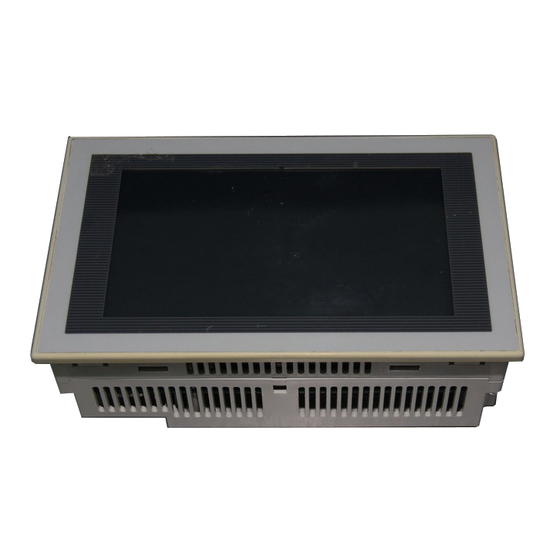
Quick Links
This manual contains text, diagrams and explanations which will guide the reader in the correct
installation, safe use and operation of the F94*GOT-*WD-E and should be read and understood before
attempting to install or use the unit. Further information can be found in the associated manuals list below.
Specifications are subject to change without notice
Guidelines for the Safety of the User and Protection of the
F940GOT-*WD-E
This manual has been written to be used by trained and competent personnel. The definition of such a
person or persons is as follows:
a) Any engineer using the product associated with this manual, should be of a competent nature,
trained and qualified to the local and national standards. These engineers should be fully aware of
all aspects of safety with regards to automated equipment.
b) Any commissioning or service engineer must be of a competent nature, trained and qualified to
the local and national standards.
c) All operators of the completed equipment should be trained to use that product in a safe and
co-ordinated manner in compliance to established safety practices.
Note: The term 'completed equipment' refers to a third party constructed device which contains or uses
the product associated with this manual.
Note's on the Symbols Used in this Manual
At various times through out this manual certain symbols will be used to highlight points of information
which are intended to ensure the users personal safety and protect the integrity of equipment.
1) Indicates that the identified danger WILL cause physical and property damage.
2) Indicates that the identified danger could POSSIBLY cause physical and property
damage.
•
Under no circumstances will Mitsubishi Electric be liable or responsible for any consequential damage
that may arise as a result of the installation or use of this equipment.
•
All examples and diagrams shown in this manual are intended only as an aid to understanding the
text, not to guarantee operation. Mitsubishi Electric will accept no responsibility for actual use of the
product based on these illustrative examples.
•
Owing to the very great variety in possible application of this equipment, you must satisfy yourself as
to its suitability for your specific application.
Associated Manuals
Manual Name
GOT-F900 Series
¤
Operation Manual
GOT-F900 Series
¤
Hardware Manual
(connection diagram)
FX-PCS-DU/WIN-E
¢
Operation Manual
SW*D5C-GOTR-PACKE
¢
Operating Manual
F9GT-40UMB
¨
Manual
¤ Indispensable manual
¢ Either manual is necessary.
¨ Refer if necessary, please.
Refer to the manual of the connected programmable controller for details concerning that unit.
Manual Number
This manual contains explanations for the
JY992D94701
operation and use of the GOT-F900 series
graphic operation terminals.
This manual contains explanations for the
JY992D94801
wiring and installation, etc. of the GOT-F900
series graphic operation terminals.
This manual contains explanations for the
JY992D68301
operation of FX-PCS-DU/WIN-E screen design
software.
This manual contains explanations for the
-
operation of GT-Designer (SW*D5C-GOTR-
PACKE) screen design software.
This manual contains explanations for
JY992D74101
installation and operating procedure of F9GT-
40UMB data transfer adapter
F940GOT Series(F940GOT-*WD-E)
Installation Manual
JY992D94201B
Description

Summary of Contents for Mitsubishi GOT-F900
- Page 1 • All examples and diagrams shown in this manual are intended only as an aid to understanding the text, not to guarantee operation. Mitsubishi Electric will accept no responsibility for actual use of the product based on these illustrative examples.
- Page 2 1) The GOT can connect to MELSEC FX, A, QnA and Q PLCs G O T as well as a host of third party manufactured units. Further information can be found in GOT-F900 Series Hardware Manual. 2) Through the GOT, PLC user programs can be downloaded, uploaded and monitored in programming software GX-Developer or FX-PCS/WIN-E on a personal computer.
- Page 3 1.2 Dimensions and Each Part Name Dimensions: mm (inches) MASS (Weight): 1 kg (2.2 lbs) Accessory: Mounting brackets, Tightening bolt (M3, 6 bolts), Packing seal for dust and water resistance P O W E R 5 ( 0 . 2 0 " ) 1 6 2 ( 6 .
- Page 4 2.2 Power Supply Specifications Items F94*GOT-SWD-E F94*GOT-LWD-E Power Supply Voltage 24V DC, +10% -15% Power Supply Ripple 200 mV or less Ratings: 410 mA at 24V DC Ratings: 390 mA at 24V DC Current Consumption 180 mA at 24 V DC when backlight is turned OFF Fuse Fuse built-in GOT (impossible to change) Max.
- Page 5 3) Fixing the GOT Put hooks of the mounting brackets (supplied) in to the mounting holes in the GOT. Tighten mounting bolts (also supplied) until the GOT is securely fixed. Fix mounting bolts in all four positions, above and below the GOT.
- Page 6 ON. The control device interlocks with an auxiliary relay in the PLC. It is recommended to provide a lamp while utilizing the output of the PLC so that voltage drop can be monitored outside the GOT. For details of control devices, refer to the GOT-F900 Series Operation Manual. Note: For approximately one month after the control device for battery voltage drop turns ON, the battery backs up the alarm history, sampling and the current time.
- Page 7 ** M is cable length. 10M: 10m (32' 9"), 20M: 20m (65' 7"), 30M: 30m (98' 5") Expansion interface text, not to guarantee operation. Mitsubishi Electric will accept no responsibility for actual use of the Communication cable (GOT ↔ CPU port in Q series PLC) product based on these illustrative examples.
- Page 8 PLC so that voltage drop can be monitored outside the GOT. Number of Colors 8 colors White and Black 2 4 V D C For details of control devices, refer to the GOT-F900 Series Operation Manual. Approximately 50,000 hours Note: (Operating temperature: 25 °C / 77°F) Life of liquid crystal 5 ( 0 .


