YASKAWA MOTOMAN FS100 Instructions Manual
Options for interface panel function, industrial robot arms
Hide thumbs
Also See for MOTOMAN FS100:
- Maintenance manual (348 pages) ,
- Instructions manual (246 pages) ,
- Option addendum (20 pages)
Table of Contents
FS100 OPTIONS
INSTRUCTIONS
FOR INTERFACE PANEL FUNCTION
Upon receipt of the product and prior to initial operation, read these instructions thoroughly, and retain
for future reference.
MOTOMAN INSTRUCTIONS
MOTOMAN-
INSTRUCTIONS
FS100 INSTRUCTIONS
FS100 OPERATOR'S MANUAL
FS100 MAINTENANCE MANUAL
YASKAWA ELECTRIC CORPORATION
Part Number: 159648-1CD
Revision: 0
MANUAL NO.
HW1480724
1/39
Table of Contents

Related Manuals for YASKAWA MOTOMAN FS100


Summary of Contents for YASKAWA MOTOMAN FS100
- Page 1 Upon receipt of the product and prior to initial operation, read these instructions thoroughly, and retain for future reference. MOTOMAN INSTRUCTIONS MOTOMAN- INSTRUCTIONS FS100 INSTRUCTIONS FS100 OPERATOR’S MANUAL FS100 MAINTENANCE MANUAL Part Number: 159648-1CD Revision: 0 YASKAWA ELECTRIC CORPORATION MANUAL NO. HW1480724 1/39...
- Page 2 If such modification is made, the manual number will also be revised. • If your copy of the manual is damaged or lost, contact a YASKAWA representative to order a new copy. The representatives are listed on the back cover. Be sure to tell the representative the manual number listed on the front cover.
- Page 3 HW1480724 FS100 Notes for Safe Operation Read this manual carefully before installation, operation, maintenance, or inspection of the FS100. In this manual, the Notes for Safe Operation are classified as “WARNING,” “CAUTION,” “MANDATORY,” or ”PROHIBITED.” Indicates a potentially hazardous WARNING situation which, if not avoided, could result in death or serious injury to personnel.
- Page 4 HW1480724 FS100 WARNING • Before operating the manipulator, check that servo power is turned off when the emergency stop button on the programing pendant is pressed. When the servo power is turned off, the SERVO ON LED on the programing pendant is turned off. Injury or damage to machinery may result if the emergency stop circuit cannot stop the manipulator during an emergency.
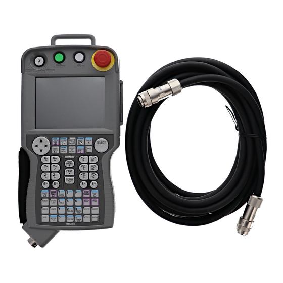
- Page 5 FS100 Instructions before operating the manipulator: Definition of Terms Used Often in This Manual The MOTOMAN is the YASKAWA industrial robot product. The MOTOMAN usually consists of the manipulator, the FS100 controller, manipulator cables, the FS100 programming pendant (optional), and the FS100 programming pendant dummy connector (optional).
- Page 6 HW1480724 FS100 Descriptions of the programming pendant keys, buttons, displays and keyboard of the PC are shown as follows: Equipment Manual Designation Programming Character Keys The keys which have characters printed on Pendant them are denoted with [ ]. ex. [ENTER] Symbol Keys The keys which have a symbol printed on them are not denoted with [ ] but depicted...
-
Page 7: Table Of Contents
HW1480724 FS100 Contents 1 Outline of Interface Panel Function....................1-1 2 Display and Operations of Panel Screen ..................2-1 2.1 Interface Panel Display...................... 2-1 2.1.1 Panel Screen Display ................... 2-1 2.1.2 Panel Screen Operation by Touch Panel ............. 2-2 2.1.3 Panel Screen Operation by PP Keys..............2-3 2.1.4 Numeric Display .................... -
Page 8: Outline Of Interface Panel Function
HW1480724 Outline of Interface Panel Function FS100 Outline of Interface Panel Function This function makes the system construction simple and enables the reduction of operation panel and Interlock panel (hereinafter called "I/L panel") by holding the roles of operation panel and I/L board in the programming pendant (hereinafter called "PP"). -
Page 9: Display And Operations Of Panel Screen
HW1480724 Display and Operations of Panel Screen FS100 Interface Panel Display Display and Operations of Panel Screen Interface Panel Display 2.1.1 Panel Screen Display Follow the operations as below to display the Interface panel. 1. Press {I/F Panel}. – The interface panel screen is displayed. 2. -
Page 10: Panel Screen Operation By Touch Panel
HW1480724 Display and Operations of Panel Screen FS100 Interface Panel Display 2.1.2 Panel Screen Operation by Touch Panel Follow the operations as below to perform ON/OFF operation on the panel screen by Touch panel. 1. Hold down [INTERLOCK] and select an appropriate button on the Touch panel. -
Page 11: Panel Screen Operation By Pp Keys
HW1480724 Display and Operations of Panel Screen FS100 Interface Panel Display 2.1.3 Panel Screen Operation by PP Keys Follow the operations as below to perform ON/OFF operation on the panel screen by PP keys. 1. Use the arrow key to move to the place where ON/OFF operation is to be performed. -
Page 12: Numeric Display
HW1480724 Display and Operations of Panel Screen FS100 Interface Panel Display 2.1.4 Numeric Display Follow the operations as below to display numeric values on the panel screen 1. Set the item "PANEL TYPE" in the I/F PANEL SETUP screen to either "Counter"... -
Page 13: Change Of Panel Screen
HW1480724 Display and Operations of Panel Screen FS100 Interface Panel Display 2.1.6 Change of Panel Screen Follow the operations as below to change the file number of Interface panel. There are two ways of changing file number. GO BACK 1. Press the page key PAGE –... -
Page 14: Data Setting And Touch Panel I/F Instructions
HW1480724 Data Setting and Touch Panel I/F Instructions FS100 Data Setting and Touch Panel I/F Instructions Set the security level to "Management" mode. Follow the operations as below to open I/F panel setting screen. 1. Select {SYSTEM INFO} under the main menu. 2. -
Page 15: Setting Procedure
HW1480724 Data Setting and Touch Panel I/F Instructions FS100 Setting Procedure Setting Procedure The procedure in the case of setting up the following table is shown. Table 3-1: Example of I/F Panel Setting Items Set Data ARRANGE SETUP INVAL ID PANEL TYPE COUNTER 3 FIGURES... -
Page 16: I/F Panel Setting Data And Display Position
HW1480724 Data Setting and Touch Panel I/F Instructions FS100 Setting Procedure 3.1.1 I/F Panel Setting Data and Display Position 1. Move the cursor to the item "ARRANGE" in the I/F panel setting screen, then press [SELECT]. – The arrangement setting screen appears. –... -
Page 17: Editing Of Setup
HW1480724 Data Setting and Touch Panel I/F Instructions FS100 Setting Procedure 3.1.2 Editing of Setup 1. Move the cursor to the item "SETUP" in the I/F panel setting screen and press [SELECT]. – The status of "SETUP" switches between "VALID" and "INVALID" with each pressing of [SELECT]. -
Page 18: Editing Of Panel Color
HW1480724 Data Setting and Touch Panel I/F Instructions FS100 Setting Procedure 3.1.4 Editing of Panel Color 1. Move the cursor to the item "PANEL COLOR" in the I/F panel setting screen and press [SELECT]. – The list of panel colors is displayed. 2. -
Page 19: Editing Of Text Color
HW1480724 Data Setting and Touch Panel I/F Instructions FS100 Setting Procedure 3.1.6 Editing of Text Color 1. Move the cursor to the item "TEXT COLOR" in the I/F panel setting screen and press [SELECT]. 2. Move the cursor to the text color to be selected and press [SELECT]. 3.1.7 Editing of Security 1. -
Page 20: Editing Of Interlock Enable
HW1480724 Data Setting and Touch Panel I/F Instructions FS100 Setting Procedure 3.1.8 Editing of Interlock Enable 1. Move the cursor to the item "INTERLOCK ENABLE" in the I/F panel setting screen and press [SELECT]. – The status of INTERLOCK ENABLE switches between "PROHIBIT" and "PERMIT"... -
Page 21: Editing Of Input
HW1480724 Data Setting and Touch Panel I/F Instructions FS100 Setting Procedure 3.1.9 Editing of Input 1. Move the cursor to the item "INPUT (DISP)" in the I/F panel setting screen and press [SELECT]. – The list of input items is displayed. 2. - Page 22 HW1480724 Data Setting and Touch Panel I/F Instructions FS100 Setting Procedure 3.1.10 Editing of Group Name 1. Select {EDIT} from the menu on the I/F panel setting screen. 2. Select {Group Name}. – The virtual keypad is displayed. 3. Enter a new group name (up to 12 one-byte characters). For character entry operation, refer to "1.2.6 Charac- SUPPLE ter Input"...
- Page 23 HW1480724 Data Setting and Touch Panel I/F Instructions FS100 Setting Procedure – The new group name is displayed in the I/F panel setting screen. 4. Press {I/F PANEL} to display the I/F PANEL screen. – The new group name is displayed in the I/F panel setting screen. 3-10 HW1480724 23/39...
-
Page 24: Initialization Of Set Data
HW1480724 Data Setting and Touch Panel I/F Instructions FS100 Setting Procedure 3.1.11 Initialization of Set Data Perform the following procedures to completely initialize the data which have been set. 1. Select {DATA} from the menu on the I/F panel setting screen. 2. -
Page 25: Details On Interface Panel Setting Items
HW1480724 Data Setting and Touch Panel I/F Instructions FS100 Details on Interface Panel Setting Items Details on Interface Panel Setting Items The following describe details on the setting items of the Interface panel screen. Refer to them as required when setting the Interface panel data. Table 3-2: Data of Each Setting Items (Sheet 1 of 2) Items Explanations... - Page 26 HW1480724 Data Setting and Touch Panel I/F Instructions FS100 Details on Interface Panel Setting Items Table 3-2: Data of Each Setting Items (Sheet 2 of 2) Items Explanations Output 0: None, 1: Signal, 2: B-variable, 3: I-variable, 4: Register Numbers differ according to the ID. (See the table table 3-1 “Example of I/F Panel Setting”...
- Page 27 HW1480724 Data Setting and Touch Panel I/F Instructions FS100 Details on Interface Panel Setting Items See the following table "Input/Output Allocation Status" when allo- cating input/output signals. Table 3-3: Input/Output Allocation Status Items Range Input Output Icon Type Allocation Allocation General input #00010 to #01287 (1024 signals) enable disable...
- Page 28 HW1480724 Data Setting and Touch Panel I/F Instructions FS100 Details on Interface Panel Setting Items • Note that the following two signals are assumed to be unused for OUT/GOUT in the CIO program. NOTE #30010 to #31287: External output Output allocation enable #35010 to #36287: DL output...
- Page 29 HW1480724 Data Setting and Touch Panel I/F Instructions FS100 Details on Interface Panel Setting Items The following table "Touch Panel I/F" describes the buttons corre- sponding to icon types. The light turns on when the status of input signal (indicated value) is ON, whereas it turns off when OFF.
-
Page 30: Save And Load Of Set Data
HW1480724 Save and Load of Set Data FS100 Save and Load of Set Data Set the security level to "Management" mode. 1. Select {FD/PC CARD} under the main menu. 2. Select {SAVE} or {LOAD}. – The external storage device screen is displayed. 3. - Page 31 HW1480724 Save and Load of Set Data FS100 5. Press [ENTER]. – The confirmation dialog box is displayed. 6. Move the cursor to "YES" and press [SELECT]. HW1480724 31/39...
-
Page 32: Editing Saved Data
HW1480724 Editing Saved Data FS100 Editing Saved Data The following explain how to modify the data which is saved in FD/PC CARD on PC. //IFPANEL 1 //NAME Panel 1, Panel 1 1A,0,0,0,1,NAME1,NAME2,NAME3,1,1,0,11111,0,0,0,0,0,0,0,NAME1,NA ME2,NAME3,0 1B,1,0,0,1,NAME1,NAME2,NAME3,1,1,0,11111,0,0,22222,1,0,0,0,NAME 1,NAME2,NAME3,0 1C,1,0,0,1,,NAME2,,1,1,0,11111,0,0,22222,1,0,0,0,NAME1,NAME2,NAM E3,0 //IFPANEL 10 ///NAME Panel 10, Panel 10 4G,0,0,0,1,NAME1,NAME2,NAME3,1,1,0,11111,0,0,0,0,0,0,0,NAME1,NA ME2,NAME3,0... - Page 33 HW1480724 Editing Saved Data FS100 2: Circle indication light (push-lock/push-release button) 3: Square indication light 1 (display only) 4: Square indication light 1 (push button) 5: Square indication light 1 (push-lock/push-release button) 6: Square indication light 2 (display only) 7: Square indication light 2 (push button) 8: Square indication light 2 (push-lock/push-release button) 9: Selector switch (left: ON) 10: Selector switch (right: ON)
-
Page 34
HW1480724 Editing Saved Data FS100 2: B-variable (B000 to B099: numbers are 3-digit) 3: I-variable (I000 to I099: numbers are 3-digit) 4: Register (M000 to M999: numbers are 3-digit)
: Number : Output Contact 1 0: A-contact 1: B-contact : Output Type 2 0: None 1: Signal (numbers are 5-digit) 2: B-variable (B000 to B099: numbers are 3-digit) -
Page 35: Parameters
HW1480724 Parameters FS100 Clearing the Status of Signals Parameters Clearing the Status of Signals By setting parameters, input/output signals at the time of power supply ON or mode change can be set to "hold" or "clear". The possible settings and the timing of status signal settings are as follows: Signals Timing of setting... -
Page 36: Status Of General Output Signals At Mode Change
HW1480724 Parameters FS100 Clearing the Status of Signals 6.1.1 Status of General Output Signals at Mode Change By setting parameters from S4C064 to S4C071, it allows to set the status of general output signals (#10010 to #11287) at the time of when changing mode. -
Page 37: Status Of Auxiliary Relay Signals At Power Supply On
HW1480724 Parameters FS100 Clearing the Status of Signals 6.1.3 Status of Auxiliary Relay Signals at Power Supply ON By setting parameters from S4C080 to S4C095, it allows to set the status of auxiliary relay signals (#70010 to #79997) at the time of when turning the power supply ON. -
Page 38: Allocation Of General Input Signals To Interface Panel Screens
HW1480724 Parameters FS100 Allocation of General Input Signals to Interface Panel Screens Allocation of General Input Signals to Interface Panel Screens By setting general input signal numbers to parameters from S4C597 to S4C607, general input signals can be allocated to interface panel screens. For the parameter settings, refer to the table below. - Page 39 FS100 OPTIONS INSTRUCTIONS FOR INTERFACE PANEL FUNCTION Specifications are subject to change without notice for ongoing product modifications and improvements. Printed in Japan September 2011 11-09 YASKAWA ELECTRIC CORPORATION MANUAL NO. HW1480724 39/39...