KitchenAid KXD4630YSS0 Technical Education
Jenn-air;unbranded.
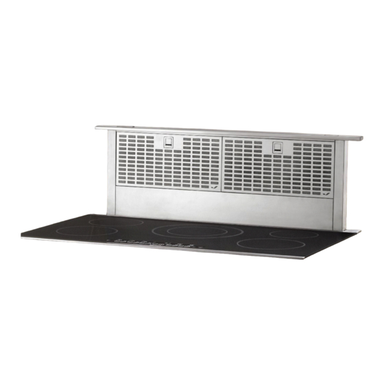
downdraft vent hood
wiring diagram
theory of operation
Hide thumbs
Also See for KXD4630YSS0:
- Use & care manual (56 pages) ,
- Installation instructions and use & care manual (30 pages)
Quick Links
See also:
Use and Care Manual

Related Manuals for KitchenAid KXD4630YSS0


Summary of Contents for KitchenAid KXD4630YSS0
- Page 1 KAC-55 TECHNICAL EDUCATION Downdraft Vent Hood Wiring Diagram Theory Of Operation KITCHENAID JENN-AIR UNBRANDED KXD4630YSS0 JXD7030YS0 UXD8630DYS0 KXD4636YSS0 JXD7036YS0 UXD8636DYS0 KXD4736YSS0 JOB AID W10754691...
-
Page 2: Goals And Objectives
FORWARD This Down Draft Vent Hood job aid provides the In- Home Service Professional with information on wiring diagrams and the theory of how the downdraft vent hood operates. For specific information on the model being serviced, refer to the literature supplied with the vent hood. Always use the Wiring Diagram supplied with the product when servicing the unit. - Page 3 TABLE OF CONTENTS DOWNDRAFT VENT HOOD JOB AID GENERAL SAFETY INFORMATION ........................1-2 COMPONENT PARTS LAYOUT ......................1-4 PRODUCT WIRING DIAGRAM ......................1-5 STRIP CIRCUITS AND THEORY OF OPERATION ..................1-6 COMPLETE DOWNDRAFT SERVICE VIDEO......(CLICK ON ICON) Section 1 .............Safety and Installation Section 2 ..............Customer Instruct Section 3 ............Theory of Operation Section 4 ...........Component Access and Testing...
- Page 4 NOTES DownDraft Vent Hood...
-
Page 5: Section 1: General Information
GENERAL INFORMATION Section 1: General Information This section provides general safety, parts, wiring diagram and theory of operation for the Downdraft Vent Hood n Safety Information n Component Layout n Product Wiring Diagram n Strip Circuits and Theory of Operation Complete Service Video - Click on Icon Downdraft Vent Hood... - Page 6 GENERAL INFORMATION DownDraft Vent Hood...
- Page 7 GENERAL INFORMATION Downdraft Vent Hood...
- Page 8 GENERAL INFORMATION Downdraft Vent Hood Component layout This Illustration shows the general location of all operational components on the downdraft vent hood. The components are numbered as shown on the product wiring diagram (next page). The wiring diagram (shown on the next page) is available on the unit and also printed in the Installation Instructions with the product.
- Page 9 GENERAL INFORMATION Shown on the Product Wiring Diagram is the component parts layout chart and within the wiring diagram the electrical components are numbered per the component chart. You can also see the adjustable blower speed switch testing information and a motor specification chart. We can come back to this diagram later if necessary, but let’s look at something a little more helpful.
- Page 10 GENERAL INFORMATION Downdraft Vent Hood diagram – different format This is a complete picture of the wiring diagram on the previous page but in a different format. This circuit shows the vent sitting idle in the down position just like the product wiring diagram. We numbered the electrical components on the diagram per the component chart on the product wiring diagram.
- Page 11 GENERAL INFORMATION The other thing that is important is what happens when the Pushbutton is pressed. A complete 120 VAC circuit is created through the two filter switches, the pushbutton (as it is being held down by the operator), and the motor to the neutral side of the line. As you notice with this circuit, until the Plenum DOWN Limit switch is closed the only power to the motor is through the pushbutton switch.
- Page 12 GENERAL INFORMATION As soon as the plenum rises to it fully open position, the Plenum UP Limit switch will change position and open the circuit to the motor. The only time we need the exhaust blower motor to run is when the plenum is fully open.
-
Page 13: Product Specifications
IN THE UNITED STATES: FOR PRODUCT SPECIFICATIONS AND WARRANTY INFORMATION CALL: FOR WHIRLPOOL PRODUCTS: 1-800-253-1301 FOR KITCHENAID PRODUCTS: 1-800-422-1230 FOR TECHNICAL ASSISTANCE WHILE AT THE CUSTOMER’S HOME CALL: THE TECHNICAL ASSISTANCE LINE: 1-800-832-7174 HAVE YOUR STORE NUMBER READY TO IDENTIFY YOU AS AN...