Table of Contents
Quick Links
See also:
Instruction Manual
Table of Contents

Related Manuals for GE 350-A9


Summary of Contents for GE 350-A9
- Page 1 Grid Solutions Feeder Protection System Feeder protection and control Quick Start Guide 350 revision: 2.3x Manual P/N: 1601-9092-AJ GE publication code: GEK-113535S E83849 LISTED *1601-9092-AJ* IND.CONT. EQ. 52TL...
- Page 2 The contents of this manual are the property of GE Multilin Inc. This documentation is furnished on license and may not be reproduced in whole or in part without the permission of GE Multilin Inc. The content of this manual is for informational use only and is subject to change without notice.
- Page 3 GENERAL SAFETY PRECAUTIONS - 350 Note • Failure to observe and follow the instructions provided in the equipment manual(s) could cause irreversible damage to the equipment and could lead to property damage, personal injury and/or death. • Before attempting to use the equipment, it is important that all danger and caution indicators are reviewed.
- Page 4 Indicates practices not related to personal injury. Note For further assistance For product support, contact the information and call center as follows: GE Grid Solutions 650 Markland Street Markham, Ontario Canada L6C 0M1 Worldwide telephone: +1 905 927 7070...
-
Page 5: Table Of Contents
Table of Contents 1. INTRODUCTION Overview ..........................1 Description of the 350 Feeder Protection System..........2 350 order codes........................5 Specifications........................9 Password security........................9 Protection.............................9 Metering............................14 Data capture ..........................14 Control ............................15 Monitoring............................17 Inputs .............................17 Outputs............................18 Power supply..........................20 Communications ........................21 Testing and certification .......................22 Physical............................23 Environmental..........................24 2. - Page 6 LED status indicators - Front panel with non-programmable LEDs ....66 LED status indicators - Front panel with programmable LEDs ......67 Relay messages........................68 Target messages........................68 Self-test errors..........................68 Flash messages ........................70 Software setup........................71 Quick setup - Software interface..................71 EnerVista 3 Series Setup Software...................
-
Page 7: Introduction
Grid Solutions 350 Feeder Protection System Chapter 1: Introduction Introduction Overview The 350 is a microprocessor-based relay for primary and backup over-current protection of medium and low voltage distribution feeders. The relay is also suitable for providing over-current and backup protection for small and medium size motors, transformers, generators, and distribution bus-bars. -
Page 8: Description Of The 350 Feeder Protection System
DESCRIPTION OF THE 350 FEEDER PROTECTION SYSTEM CHAPTER 1: INTRODUCTION Description of the 350 Feeder Protection System Relay functions are controlled by two processors: a Freescale MPC5554 32-bit microprocessor measures all analog signals and digital inputs and controls all output relays;... - Page 9 CHAPTER 1: INTRODUCTION DESCRIPTION OF THE 350 FEEDER PROTECTION SYSTEM Figure 1-1: Functional block diagram BUS VT 59_2 TRIP CLOSE MONITORING I /I 50_2 51_2 METERING TRANSIENT RECORDER EVENT RECORDER FAULT REPORT 50P HS SENSORS 350 RELAY Y 50G/ VTFF 50BF 50G/SG 51G/SG 67G/SG...
- Page 10 DESCRIPTION OF THE 350 FEEDER PROTECTION SYSTEM CHAPTER 1: INTRODUCTION ANSI Code 61850 Logical Node Description ndPTOV1, nfPTOV2, Neutral Overvoltage ndPTOV3, ndPTOV4 phsPTOV1, phsPTOV2, Phase Overvoltage phsPTOV3, phsPTOV4 auxPTOV1 Auxiliary Overvoltage 60CTS CT Supervision 67G/SG gndRDIR1/hseRDIR1 Ground/Sensitive Ground Directional Element ndRDIR1 Neutral Directional Element phsRDIR1...
-
Page 11: 350 Order Codes
CHAPTER 1: INTRODUCTION 350 ORDER CODES Description Output Relays PRP Communications Relay Maintenance Remote Inputs (32) Setpoint Groups (2) Test Mode Transient Recorder (Oscillography) Trip and Close Coil Monitoring User Curves User-programmable LEDs Virtual Inputs (32) Virtual Outputs (32) Figure 1-2: Main Menu structure ACTUAL VALUES ACTUAL VALUES COMMANDS... - Page 12 350 ORDER CODES CHAPTER 1: INTRODUCTION Figure 1-3: Order Codes * Interface 350 Feeder Protection System User Interface English without programmable LEDs English with programmable LEDs PX | No CT Phase Currents P0 | 1 A or 5 A configurable phase current inputs P1 | 1 A 3-phase current inputs P5 |...
- Page 13 CHAPTER 1: INTRODUCTION 350 ORDER CODES Features related to each order number are subject to change without notice. NOTE: Arc Flash System The 350 protection relay with Input/Output option “A” supports up to 4 Arc Flash sensors, which are ordered separately so that the connected sensor fiber lengths can be customized.
- Page 14 350 ORDER CODES CHAPTER 1: INTRODUCTION Figure 1-4: 350 chassis order codes 350 CH * Phase Currents 1 A 3-phase current inputs 5 A 3-phase current inputs G1 | 1 A ground current input Ground Currents 5 A ground current input 1 A sensitive ground current input 5 A sensitive ground current input Other Options...
-
Page 15: Specifications
CHAPTER 1: INTRODUCTION SPECIFICATIONS Specifications Specifications are subject to change without notice. NOTE: To obtain the total element operating time, i.e. from the presence of a trip condition to NOTE: initiation of a trip, add 8 ms output relay time to the operate times listed below, with the exception of Arc Flash SSR loads. - Page 16 SPECIFICATIONS CHAPTER 1: INTRODUCTION DIRECTIONAL POWER (32) Measured power:..........3-phase Characteristic angle:......... 0º to 359º in steps of 1° Power pickup range: ......... -1.200 to 1.200 x Rated Power in steps of 0.001 Pickup level accuracy:........2.5% or 0.01 pu, whichever is greater Hysteresis: .............
- Page 17 CHAPTER 1: INTRODUCTION SPECIFICATIONS PHASE/NEUTRAL/GROUND/NEGATIVE SEQUENCE INSTANTANEOUS OVERCURRENT (50P/50N/50G/50_2) Pickup Level:............0.05 to 20.00 x CT in steps of 0.01 x CT Dropout Level: ............97% of Pickup @ I > 1 x CT Pickup - 0.02 x CT @ I <1 x CT Time Delay:............
- Page 18 SPECIFICATIONS CHAPTER 1: INTRODUCTION NEUTRAL DIRECTIONAL (67N) Directionality: ............Forward and reverse Polarizing:............... Voltage, Current, Dual Polarizing Voltage:..........- V calculated using phase voltages (VTs must be connected in “Wye”) measured from Vaux input (3V provided by an external broken delta connection). Polarizing Current:..........
- Page 19 CHAPTER 1: INTRODUCTION SPECIFICATIONS PHASE/AUXILIARY/NEUTRAL/NEGATIVE SEQUENCE OVERVOLTAGE (59P, 59X, 59N, 59_2) Pickup Level:............0.00 to 1.25 x VT in steps of 0.01 Dropout Level: ............98% of pickup (pickup > 0.1 x VT) Pickup - 0.02 x VT (pickup < 0.1 x VT) Time Delay:............
-
Page 20: Metering
SPECIFICATIONS CHAPTER 1: INTRODUCTION Metering PARAMETER ACCURACY RESOLUTION RANGE (full scale for CT Input is 3 x CT) 3-Phase Real Power (MW or kW) ±1% of full scale 0.1 MW ± 100000.0 kW 3-Phase Reactive Power (Mvar or kvar) ±1% of full scale 0.1 Mvar ±... -
Page 21: Control
CHAPTER 1: INTRODUCTION SPECIFICATIONS EVENT RECORDER Number of events:..........256 Header: ..............relay name, order code, firmware revision Content:..............event number, date of event, cause of event,per-phase current, ground current, sensitive ground current, neutral current, per-phase voltage (VTs connected in “Wye”), or phase-phase voltages (VTs connected in “Delta”), system frequency, power, power factor, thermal capacity Data Storage:............Retained for 3 days CLOCK... - Page 22 SPECIFICATIONS CHAPTER 1: INTRODUCTION BREAKER FAILURE (50BF) Pickup Level: ............0.05 to 20.00 x CT in steps of 0.01 x CT Dropout Level:............97 to 98% of pickup Timer 1 Delay:............0.03 to 1.00 s in steps of 0.01 s Timer 2 Delay:............
-
Page 23: Monitoring
CHAPTER 1: INTRODUCTION SPECIFICATIONS Monitoring BREAKER HEALTH Timer Accuracy: ..........± 3% of delay setting or ± 1 cycle (whichever is greater) from pickup to operate DEMAND Measured Values:..........Phase A/B/C present and maximum current, three-phase present and maximum real/reactive/apparent power Measurement Type:...........Thermal Exponential, 90% response time (programmed): 5, 10, 15, 20, 30 minutes Block Interval / Rolling Demand, time interval (programmed): 5, 10, 15, 20, 30 minutes... -
Page 24: Outputs
SPECIFICATIONS CHAPTER 1: INTRODUCTION SENSITIVE GROUND CURRENT INPUT CT Primary: ............1 to 600 A Range:..............0.002 to 3 × CT Input type:.............. 1 A, 5 A, or 1/5 A (must be specified with order) Nominal frequency:........... 50/60 Hz Burden: ..............<0.1 VA at rated load Accuracy: ............... - Page 25 CHAPTER 1: INTRODUCTION SPECIFICATIONS FORM-C RELAYS Configuration:............3 (three) electromechanical Contact material: ..........silver-alloy Operate time:............<8 ms Continuous current:........... 10 A Make and carry for 0.2s:........30 A per ANSI C37.90 Break (DC inductive, L/R=40 ms):....24 V / 1 A 48 V / 0.5 A 125 V / 0.3 A 250 V / 0.2 A...
-
Page 26: Power Supply
SPECIFICATIONS CHAPTER 1: INTRODUCTION FORM-A VOLTAGE MONITOR Applicable voltage:..........20 to 250 VDC Trickle current: ............. 1 to 2.5 mA FORM-C RELAYS Configuration: ............5 (five) electromechanical Contact material:..........silver-alloy Operate time:............<8 ms Continuous current:........... 10 A Make and carry for 0.2s: ......... 30 A per ANSI C37.90 Break (DC inductive, L/R=40 ms):.... -
Page 27: Communications
CHAPTER 1: INTRODUCTION SPECIFICATIONS Communications SERIAL RS485 port: ............Opto-coupled Baud rates:.............up to 115 kbps Response time:.............1 ms typical Parity: ...............None, Odd, Even Protocol: ..............Modbus RTU, DNP 3.0, IEC 60870-5-103 Maximum distance: ...........1200 m (4000 feet) Isolation:..............2 kV ETHERNET (COPPER) Modes:..............10/100 MB (auto-detect) Connector:..............RJ-45 Protocol: ..............Modbus TCP, DNP3.0, IEC 60870-5-104, IEC 61850 GOOSE, IEC 61850, OPC-UA... -
Page 28: Testing And Certification
SPECIFICATIONS CHAPTER 1: INTRODUCTION Testing and certification TYPE TESTS TEST REFERENCE STANDARD TEST LEVEL Dielectric voltage withstand (high voltage power supply*) 60255-27 2200 VAC for one second (low voltage power supply*) 60255-27 550 VAC for one second * Test level is based on basic insulation principle (Power supply I/P terminals tested to Chassis ground). -
Page 29: Physical
CHAPTER 1: INTRODUCTION SPECIFICATIONS APPROVALS Applicable Council Directive According to: Low voltage directive 2014/35/EU CE compliance EMC Directive 2014/30/EU UL 508 North America cULus UL 1053 C22.2. No 14 Machines and Equipment TR CU 010/2011 Lloyd’s Register Rules and Regulations for the Marine Applications: ENV2, ENV3 Classifications of Ships IEC 61850... -
Page 30: Environmental
SPECIFICATIONS CHAPTER 1: INTRODUCTION Environmental OPERATING ENVIRONMENT Ambient temperatures: Storage/Shipping: C to 85 Operating: C to 60 Humidity: Operating up to 95% (non condensing) @ 55 C (As per IEC60068-2-30 Variant 2, 6 days) Altitude: 2000 m (max) Pollution Degree: Overvoltage Category: Ingress Protection: IP54 Front, IP20 cover (optional) -
Page 31: Installation
Grid Solutions 350 Feeder Protection System Chapter 2: Installation Installation Mechanical installation This section describes the mechanical installation of the 350 system, including dimensions for mounting and information on module withdrawal and insertion. This equipment is Suitable for mounting on the flat surface of a Type 1 Enclosure 350 FEEDER PROTECTION SYSTEM –... -
Page 32: Dimensions
MECHANICAL INSTALLATION CHAPTER 2: INSTALLATION Dimensions The dimensions of the 350 are on the following pages. Additional dimensions for mounting and panel cutouts are shown in the following sections. Figure 2-1: 350 dimensions - Drawout unit 1 0 7 350 FEEDER PROTECTION SYSTEM – QUICKSTART GUIDE... - Page 33 CHAPTER 2: INSTALLATION MECHANICAL INSTALLATION Figure 2-2: 350 dimensions - Non-drawout unit 3.96" (100.6mm) " 7.88" (200.2mm) 1.47" (37.3mm) 7.98" 6.82" (202.7mm) (173.2mm) 6.23" (158.2mm) 350 FEEDER PROTECTION SYSTEM – QUICKSTART GUIDE...
-
Page 34: Product Identification
Technical Support: Multilin Worldwide: +1 905 927 7070 Feeder Protection System North America: 1 800 547 8629 www.gegridsolutions.com/multilin/ Model:350-E-P1-G1-H-E-S-N-M-2E-N-N GE POWER MANAGEMENT S.L. Serial Number:BL1A16000098 AV Pinoa 10, 48170 Zamudio, Spain ML1A160000988 MFG. Date: M ar. 11, 2017 Power Supply:... - Page 35 CHAPTER 2: INSTALLATION MECHANICAL INSTALLATION Figure 2-4: Standard panel mounting - Drawout 8 - 32X3/8IN P/HD PHIL BLK GE PART # 1408-0306; (QTY:8) TIGHTENING TORQUE: 15 IN LB Figure 2-5: Standard Panel mounting - Non-drawout 8-32 x 3/8" P/HD PHIL BLK GE P/N 1408-0306 (QTY:8) Tightening Torque: 15 in-lb (1.7 Nm)
- Page 36 MECHANICAL INSTALLATION CHAPTER 2: INSTALLATION Figure 2-6: Depth Reducing collar (optional) Panel mounting with depth reducing collar: Mount the collar of required depth (1.375” or 3”) to the unit (captive or non-drawout) using 4 screws (see above). Mount the combination of unit and collar to the panel using 4 screws as shown above. Figure 2-7: Mounting tabs (optional) “V”...
- Page 37 CHAPTER 2: INSTALLATION MECHANICAL INSTALLATION If added security is required, bend the retaining "V"tabs outward, to about 90°. These tabs are located on the sides of the case and appear as shown above. The relay can now be inserted and can be panel wired. Figure 2-8: Panel cutout dimensions 5.350”...
-
Page 38: Mounting Using The S1/S2/Mdp/Iac Or Sr735 Adapter Plate
GE PART#: 1408-0015 (FRONT SURFACE OUTSIDE) PER THE VIEW. MAKE SURE QTY: 8 THE MOUNTING SCREWS (GE PART# 1410-0112) DO NOT TIGHTENING TORQUE: 15 LB-IN PENETRATE THROUGH THE ADAPTER PLATE FRONT SURFACE. - MOUNT THE CAPTIVE UNIT WITH THE ADAPTER PLATE. - Page 39 CHAPTER 2: INSTALLATION MECHANICAL INSTALLATION Figure 2-10: Non-drawout - Adapter plate mounting 8.000” #10-32 NUT 203.2 mm QTY: 4 6.123” 155.5 mm 9.750” 11.000” 247.7 mm 279.4 mm 350 ADAPTER PLATE FOR SR735 350 FEEDER PROTECTION SYSTEM – QUICKSTART GUIDE...
- Page 40 MECHANICAL INSTALLATION CHAPTER 2: INSTALLATION Figure 2-11: Panel cutout dimensions 5.350” 0.010” ± (135.9 mm 0.25mm) ± 4.100” 0.010” ± (104.1 mm 0.25 mm) ± Φ 0.200” (5.1 mm) 6.900” 0.010” ± (175.3 mm 0.25 mm) ± 6.000” 0.010” ± (152.4 mm 0.25 mm) ±...
-
Page 41: Drawout Unit Withdrawal And Insertion
MECHANICAL INSTALLATION Drawout unit withdrawal and insertion Figure 2-12: Unit withdrawal and insertion diagram 8 - 32X3/8IN P/HD PHIL BLK GE PART # 1408-0306; (QTY:8) TIGHTENING TORQUE: 15 IN LB THE HANDLE MUST BE ROTATED 90 ⁰ WHILE SLIDING THE DRAW-OUT... -
Page 42: Ip20 Cover (Optional)
MECHANICAL INSTALLATION CHAPTER 2: INSTALLATION IP20 Cover (optional) The IP20 cover minimizes potential dangers to users by preventing finger contact with electrical connections at the back of the 3 Series drawout units. Attaching the cover The steps for attaching the IP20 cover (optional) to the drawout unit are as follows: Figure 2-13: IP20 Cover mounting - Drawout unit only Place 4 custom standoffs (item#1) using the suggested tightening torque of 8lb-in in the following order:... -
Page 43: Arc Flash Sensors
CHAPTER 2: INSTALLATION MECHANICAL INSTALLATION Arc flash sensors Arc flash sensors house the fiber optics that are used to detect the arc flash. Mounting details depend on the sensor type (point or loop). For detailed installation, testing and maintenance guidance for Arc Flash sensors, see GET- 20057 3 Series Arc Flash Application Note. -
Page 44: Sensor Fiber Handling & Storage
MECHANICAL INSTALLATION CHAPTER 2: INSTALLATION Arc flash sensors of either type can be connected to any of the four arc flash ports on the back of the 350 relay, as shown. Figure 2-14: Arc flash sensors connected to a 350 relay Sensor fiber handling &... -
Page 45: Point Sensor Installation
CHAPTER 2: INSTALLATION MECHANICAL INSTALLATION • Avoid surface temperatures above 70 °C or 158 °F to prolong the life of the fiber. • Secure all sensor fibers (loosely but securely) away from any moving parts. Point sensor Figure 2-15: Arc flash point sensor without sensor fiber connected installation Figure 2-16: Point sensor and slim connector dimensions 350 FEEDER PROTECTION SYSTEM –... - Page 46 MECHANICAL INSTALLATION CHAPTER 2: INSTALLATION Figure 2-17: Duplex connector dimensions (point sensor, and sensor fiber extension for loop sensor) The point sensor fiber includes a duplex connector to connect to the back of the 350 relay on one end, and a compressed slim connector that connects to the sensor itself on the other end.
- Page 47 CHAPTER 2: INSTALLATION MECHANICAL INSTALLATION The slim connecter fits through holes with a radius of 11 mm or greater, and can be threaded through holes drilled in any panels between the relay and arc flash detection location. Install protective grommets when routing sensor fiber through metal walls. NOTE: Mount the point sensor using either a cable tie mount or through-hole mount, as NOTE...
- Page 48 MECHANICAL INSTALLATION CHAPTER 2: INSTALLATION Through-hole mount • Requires a standard or self-tapping M3 screw, and optionally an M3 washer. • Mount the sensor through a 10 mm hole made in the surface of any mechanical structure inside the switchgear or on the surface of one side of the switchgear itself, as shown in the following figure.
-
Page 49: Loop Sensor Installation
CHAPTER 2: INSTALLATION MECHANICAL INSTALLATION Loop sensor The loop sensor transparent sensor fiber has a single connector on either end. The sensor installation fiber extension has a duplex connector on one end, two single connectors on the other end, and comes with two single bulkhead connectors. Both come in custom lengths, which can be ordered to fit your installation. - Page 50 MECHANICAL INSTALLATION CHAPTER 2: INSTALLATION Figure 2-22: Duplex connector dimensions (point sensor, and sensor fiber extension for loop sensor) Figure 2-23: Single bulkhead connector dimensions 350 FEEDER PROTECTION SYSTEM – QUICKSTART GUIDE...
- Page 51 CHAPTER 2: INSTALLATION MECHANICAL INSTALLATION Figure 2-24: Single bulkhead connector with single connectors and sensor fiber Before installing the AF sensor units, ensure that all other drilling and installation is complete to minimize possible damage to the sensitive unit and connected sensor fiber cable.
-
Page 52: Electrical Installation
ELECTRICAL INSTALLATION CHAPTER 2: INSTALLATION Electrical installation This section describes the electrical installation of the 350 system, including typical wiring diagrams and terminal identification. 350 FEEDER PROTECTION SYSTEM – QUICKSTART GUIDE... -
Page 53: Typical Wiring Diagrams
CHAPTER 2: INSTALLATION ELECTRICAL INSTALLATION Typical wiring diagrams Figure 2-26: Typical wiring diagram - Drawout DIRECTION OF POWER FLOW FOR POSITIVE WATTS POSITIVE DIRECTION OF LAGGING VARs A B C FEEDER Cts BUS Vts FEEDER 1A OR 5A WYE VT ECTIO ECT AUX_VT AS REQUIRED... - Page 54 POWER SUPPLY CURRENT INPUTS VOLTAGE INPUTS GND STUD GROUND TRIP CIRCUIT TRIP Breaker Aux Contacts 1 TRIP COIL GE Multilin 52a (C1 #1) CLOSE 52b (C1 #2) CIRCUIT 2 CLOSE CLOSE COIL INPUT 3 Feeder Protection System INPUT 4 INPUT 5...
-
Page 55: 350 Terminal Identification
CHAPTER 2: INSTALLATION ELECTRICAL INSTALLATION 350 Terminal identification When installing two lugs on one terminal, both lugs should be "right side up" as shown in NOTE: the picture below. This is to ensure the adjacent lower terminal block does not interfere with the lug body. - Page 56 ELECTRICAL INSTALLATION CHAPTER 2: INSTALLATION Figure 2-30: INCORRECT INSTALLATION METHOD (lower lug reversed) 350 FEEDER PROTECTION SYSTEM – QUICKSTART GUIDE...
- Page 57 CHAPTER 2: INSTALLATION ELECTRICAL INSTALLATION Figure 2-31: 350 Terminal Identification - standard(drawout) IRIG-B + POWER SUPPLY + INPUT 1 IRIG-B - POWER SUPPLY - RS485 + CHASSIS GND RS485 - INPUT 2 TRIP N/O RS485 COM TRIP COM CHASSIS GND INPUT 3 RESERVED TRIP OPTV...
-
Page 58: Wire Range
ELECTRICAL INSTALLATION CHAPTER 2: INSTALLATION Figure 2-32: 350 Terminal Identification - Non-drawout INPUT 1 POWER SUPPLY + INPUT 2 POWER SUPPLY - INPUT 3 CHASSIS GND INPUT 4 INPUT 5 INPUT 6 INPUT 7 TRIP N/O INPUT 8 TRIP COM INPUT 9 TRIP OPTV INPUT 10... -
Page 59: Current Inputs
CHAPTER 2: INSTALLATION ELECTRICAL INSTALLATION Current inputs The 350 relay has four (4) channels for AC current inputs, each with an isolating transformer. There are no internal ground connections on the current inputs. Current transformers with 1 to 6000 A primaries may be used. Verify that the relay’s nominal input current of 1 A or 5 A matches the secondary rating CAUTION: of the connected CTs. -
Page 60: Zero Sequence Ct Installation
ELECTRICAL INSTALLATION CHAPTER 2: INSTALLATION Figure 2-33: Ground/Sensitive Ground wiring SOURCE PHASE CURRENT INPUTS GROUND GROUND GROUND GROUND CURRENT INPUT GROUND CURRENT INPUT GROUND CURRENT INPUT USED FOR POLARIZING WITH ZERO SEQUENCE CT WITH RESIDUAL CONNECTION 898730A1.CDR Zero sequence CT installation The various CT connections and the exact placement of a Zero Sequence CT, for ground fault current detection, are shown in the figure below. -
Page 61: Voltage Inputs
CHAPTER 2: INSTALLATION ELECTRICAL INSTALLATION Voltage inputs The 350 relay has four channels for AC voltage inputs, each with an isolating transformer. Voltage transformers up to a maximum 5000:1 ratio may be used. The nominal secondary voltage must be in the 50 to 240 V range.The three phase inputs are designated as the “bus voltage”. -
Page 62: Contact Inputs
ELECTRICAL INSTALLATION CHAPTER 2: INSTALLATION An external switch, circuit breaker, or other protective device must be connected near to NOTE: the equipment. NOTE Figure 2-36: Control power connection CONTROL P P OWER HEAVY COPPER CONDUCTOR HEAVY COPPER CONDUCTOR OR BRAIDED WIRE OR BRAIDED WIRE SWITCHGEAR GROUND BUS... -
Page 63: Trip And Close Output Relays
CHAPTER 2: INSTALLATION ELECTRICAL INSTALLATION Trip and Close output relays The 350 relay is equipped with seven electromechanical output relays: two special relays designed for Breaker trip and close (Relay 1 “Trip”, Relay 2 “Close”), four general purpose relays (Auxiliary Relays 3 to 6), and a Critical Failure relay. The special purpose relays have fixed operating characteristics and the general purpose relays can be configured by the user. - Page 64 ELECTRICAL INSTALLATION CHAPTER 2: INSTALLATION To monitor the close coil circuit integrity, use the relay terminals B4 and A4 to connect the NOTE: Close coil, and provide a jumper between terminals B4 (optional voltage) and B5. NOTE Figure 2-38: Trip and Close circuits with no voltage monitoring DC + DC + Output Relay 1 (TRIP)
-
Page 65: Serial Communications
CHAPTER 2: INSTALLATION ELECTRICAL INSTALLATION Serial communications Figure 2-40: RS485 wiring diagram 3 Series IED TWISTED PAIR SHIELD Z (*) RS485 + OPTOCOUPLER OPTOCOUPLER RS485 - DATA DATA SCADA, PLC, OR COMMON PERSONAL COMPUTER GROUND THE SHIELD AT THE SCADA/PLC/COMPUTER ONLY OR THE SR3 ONLY RS485 + (*) TERMINATING IMPEDANCE AT EACH END... -
Page 66: Irig-B
The uncovered communications cable shield connected to the common terminal should not exceed 1” (2.5 cm) for proper EMC shielding of the communications cable. Figure 2-41: IRIG-B connection GPS SATELLITE SYSTEM GPS CONNECTION OPTIONAL GE MULTILIN IRIG-B 3 SERIES RELAY RG58/59 COAXIAL CABLE TIME CODE GENERATOR... - Page 67 Grid Solutions 350 Feeder Protection System Chapter 3: Interfaces Interfaces There are two methods of interfacing with the 350 Feeder Protection System. • Interfacing via the relay keypad and display. • Interfacing via the EnerVista 3 Series Setup software. This section provides an overview of the interfacing methods available with the 350 using the relay control panels and EnerVista 3 Series Setup software.
-
Page 68: Interfaces Front Control Panel Interface
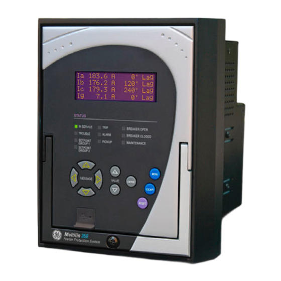
FRONT CONTROL PANEL INTERFACE CHAPTER 3: INTERFACES Front control panel interface Figure 3-1: 350 Feeder Protection System Front Panel - Non-programmable LEDs GE Multilin 350 Feeder Protection System TRIP BREAKER OPE I SERVICE TROUBLE ALARM BREAKER CLOSED SETPOI T PICKUP... -
Page 69: Description
CHAPTER 3: INTERFACES FRONT CONTROL PANEL INTERFACE Figure 3-2: 350 Feeder Protection System Front Panel - Programmable LEDs Description The relay front panel provides an interface with a liquid crystal display, LED status indicators, control keys, and a USB program port. The display and status indicators show the relay information automatically. -
Page 70: Display
FRONT CONTROL PANEL INTERFACE CHAPTER 3: INTERFACES Display The 80-character liquid crystal display (LCD) allows visibility under varied lighting conditions. When the keypad and display are not being used, system information is displayed after a user-defined period of inactivity. Pressing the Menu key during the display of default message returns the display to the last message shown before the default message appeared. - Page 71 CHAPTER 3: INTERFACES FRONT CONTROL PANEL INTERFACE When the display shows SETPOINTS, pressing the MESSAGE ► key or the ENTER key will display the page headers of programmable parameters (referred to as setpoints in the manual). When the display shows ACTUAL VALUES, pressing the MESSAGE ► key or the ENTER key displays the page headers of measured parameters (referred to as actual values in the manual).
-
Page 72: Led Status Indicators - Front Panel With Non-Programmable Leds
FRONT CONTROL PANEL INTERFACE CHAPTER 3: INTERFACES LED status indicators - Front panel with non-programmable LEDs • IN SERVICE: Green This LED will be continuously “ON”, when the relay is set to “Ready” under S1 RELAY SETUP > INSTALLATION > RELAY STATUS , and no major self-test errors have been detected. -
Page 73: Led Status Indicators - Front Panel With Programmable Leds
CHAPTER 3: INTERFACES FRONT CONTROL PANEL INTERFACE LED status indicators - Front panel with programmable LEDs • IN SERVICE: Green This LED will be continuously “ON”, when the relay is set to “Ready” under S1 RELAY SETUP > INSTALLATION > RELAY STATUS , and no major self-test errors have been detected. -
Page 74: Relay Messages
FRONT CONTROL PANEL INTERFACE CHAPTER 3: INTERFACES Relay messages Target messages Target messages are automatically displayed for any active condition on the relay such as pickups, trips, or alarms. The relay displays the most recent event first, and after 5 seconds will start rolling up the other target messages until the conditions clear and/or the RESET command is initiated. - Page 75 CHAPTER 3: INTERFACES FRONT CONTROL PANEL INTERFACE • Record the minor self-test error in the Event Recorder. Upon detection of a major problem, the relay will: • De-energize critical failure relay (Output Relay 7). • Inhibit operation of all other output relays (1 to 6). •...
-
Page 76: Flash Messages
FRONT CONTROL PANEL INTERFACE CHAPTER 3: INTERFACES Self-test Error Latched Description of How Often the Test What to do Message Target Problem is Performed Message? MAINTENANCE The ambient Every 1 hour Increase ventilation to the ALERT: High temperature is surroundings. Ambient above 80 Temperature... -
Page 77: Software Setup
CHAPTER 3: INTERFACES SOFTWARE SETUP Software setup Quick setup - Software interface • The Quick Setup window allows you to configure important settings from different screens in the relay by adding them to a common window. • Quick Setup window options are available for a single device or a file. •... -
Page 78: Enervista 3 Series Setup Software
500 MB free hard drive space (1 GB recommended) • 1024 x 768 display (1280 x 800 recommended) The EnerVista 3 Series Setup software can be installed from either the GE EnerVista CD or the GE Multilin website at http://www.gegridsolutions.com/multilin... - Page 79 CHAPTER 3: INTERFACES SOFTWARE SETUP In the EnerVista Launchpad window, click the Add Product button and select the 350 Feeder Protection System as shown below. Select the Web option to ensure the most recent software release, or select CD if you do not have a web connection, then click the Add Now button to list software items for the 350 .
- Page 80 SOFTWARE SETUP CHAPTER 3: INTERFACES If you are going to communicate from your computer to the 350 Relay using the USB port: 10. Plug the USB cable into the USB port on the 350 Relay then into the USB port on your computer.
-
Page 81: Upgrading The Software
(for USB communications) or to the RS485 terminals on the back of the device (for RS485 communications). This example demonstrates an USB connection. For RS485 communications, the GE Multilin F485 converter will be required. Refer to the F485 manual for additional details. To configure the relay for Ethernet communications, see Configuring Ethernet Communications below. -
Page 82: Using The Quick Connect Feature
SOFTWARE SETUP CHAPTER 3: INTERFACES Click the Read Order Code button to connect to the 350 device and upload the order code. Click OK when the relay order code has been received. The new device will be added to the Site List window (or Online window) located in the top left corner of the main EnerVista 3 Series Setup window. -
Page 83: Configuring Ethernet Communications
Install and start the latest version of the EnerVista 3 Series Setup Setup software NOTE (available from the GE EnerVista CD). See the previous section for the installation procedure. Click on the Device Setup button to open the Device Setup window and click the Add Site button to define a new site. -
Page 84: Connecting To The Relay
SOFTWARE SETUP CHAPTER 3: INTERFACES Enter the IP address, slave address, and Modbus port values assigned to the 350 relay (from the S1 RELAY SETUP > COMMUNICATIONS > ETHERNET menu). Click the Read Order Code button to connect to the 350 and upload the order code. If a communications error occurs, ensure that the Ethernet communication values correspond to the relay setting values. -
Page 85: Working With Setpoints And Setpoint Files
CHAPTER 3: INTERFACES SOFTWARE SETUP The Front Panel settings window opens with a corresponding status indicator on the lower left of the EnerVista 3 Series Setup window. If the status indicator is red, verify that the serial, USB, or Ethernet cable is properly connected to the relay, and that the relay has been properly configured for communications (steps described earlier). - Page 86 SOFTWARE SETUP CHAPTER 3: INTERFACES Clicking the arrow at the end of the box displays a numerical keypad interface that allows the user to enter a value within the setpoint range displayed near the top of the keypad: Click = to exit from the keypad and keep the new value. Click on X to exit from the keypad and retain the old value.
-
Page 87: Setting Programmable Leds
CHAPTER 3: INTERFACES SOFTWARE SETUP Setting Front panels with programmable LEDs have eight LEDs that are off by default, and must programmable LEDs be set to a source signal and type. Four of these LEDs can also be set to different colors. Establish communications with the relay. -
Page 88: File Support
SOFTWARE SETUP CHAPTER 3: INTERFACES Click Print to print a copy of the customized front panel label. File support Opening any EnerVista 3 Series Setup file will automatically launch the application or provide focus to the already opened application. If the file is a settings file (has a ‘SR3’ extension) which had been removed from the Settings List tree menu, it will be added back to the Settings List tree. -
Page 89: Downloading And Saving Setpoint Files
CHAPTER 3: INTERFACES SOFTWARE SETUP Downloading and Back up a copy of the in-service settings for each commissioned 350 unit, so as to revert saving setpoint files to the commissioned settings after inadvertent, unauthorized, or temporary setting changes are made, after the settings default due to firmware upgrade, or when the unit has to be replaced. -
Page 90: Creating A New Setpoint File
Discontinued order codes may be included to maintain back-compatibility of setpoint files. NOTE: For current order codes, refer to the GE Multilin website at http:// www.gegridsolutions.com/multilin. NOTE... -
Page 91: Upgrading Setpoint Files To A New Revision
1.20, change the setpoint file revision to “1.4x”. Discontinued order codes may be included to maintain back-compatibility of setpoint files. NOTE: For current order codes, refer to the GE Multilin website at http:// www.gegridsolutions.com/multilin. -
Page 92: Printing Setpoints And Actual Values
SOFTWARE SETUP CHAPTER 3: INTERFACES Printing setpoints and The EnerVista 3 Series Setup software allows the user to print partial or complete lists of actual values setpoints and actual values. Use the following procedure to print a list of setpoints: Select a previously saved setpoints file in the File pane or establish communications with a 350 device. -
Page 93: Loading Setpoints From A File
CHAPTER 3: INTERFACES SOFTWARE SETUP Loading setpoints from a file An error message will occur when attempting to download a setpoint file with a CAUTION: revision number that does not match the relay firmware. If the firmware has been upgraded since saving the setpoint file, see for instructions on changing the revision number of a setpoint file. -
Page 94: Upgrading Relay Firmware
To upgrade the 350 firmware, follow the procedures listed in this section. Upon successful completion of this procedure, the 350 will have new firmware installed with the factory default setpoints.The latest firmware files are available from the GE Multilin website at http://www.GEgridsolutions.com/multilin. - Page 95 CHAPTER 3: INTERFACES SOFTWARE SETUP The EnerVista 3 Series Setup software will notify the user when the 350 has finished loading the file. Carefully read any displayed messages and click OK to return the main screen. Cycling power to the relay is recommended after a firmware upgrade. After successfully updating the 350 firmware, the relay will not be in service and will require setpoint programming.
-
Page 96: Advanced Enervista 3 Series Setup Features
SOFTWARE SETUP CHAPTER 3: INTERFACES Advanced EnerVista 3 Series Setup features Flexcurve editor The FlexCurve Editor is designed to allow the user to graphically view and edit the FlexCurve. The Flexcurve Editor screen is shown below: • The Operate Curves are displayed, which can be edited by dragging the tips of the curves •... -
Page 97: Transient Recorder (Waveform Capture)
CHAPTER 3: INTERFACES SOFTWARE SETUP • The user can save Configured Trip Times. • The user can export Configured Trip Times to a CSV file • The user can load Trip Times from a CSV File • The screen above shows the model followed by 350 for viewing Flexcurves. Select Initialize to copy the trip times from the selected curve to the FlexCurve. - Page 98 SOFTWARE SETUP CHAPTER 3: INTERFACES DELTA TRIGGER TIME & DATE VECTOR DISPLAY SELECT CURSOR LINE POSITION Indicates time difference Indicates the cursor line position Displays the time and date Click here to open a new graph in time with respect to the between the two cursor of the Trigger.
- Page 99 CHAPTER 3: INTERFACES SOFTWARE SETUP Preference Button The following window will appear: Change the color of each graph as desired, and select other options as required, by checking the appropriate boxes. Click OK to store these graph attributes, and to close the window.
-
Page 100: Protection Summary
SOFTWARE SETUP CHAPTER 3: INTERFACES Protection summary Protection Summary is a single screen which holds the summarized information of different settings from Grouped Elements, Control Elements and Maintenance screens. Protection Summary Screen allows the user to: • view the output relay assignments for the elements •... - Page 101 CHAPTER 3: INTERFACES SOFTWARE SETUP 350 FEEDER PROTECTION SYSTEM – QUICKSTART GUIDE...
-
Page 102: Password Security
SOFTWARE SETUP CHAPTER 3: INTERFACES Password security Password security is an optional feature of the 350 which can be setup using the EnerVista 3 Series Setup software. The password system has been designed to facilitate a hierarchy for centralized management. This is accomplished through a Master level access password which can be used for resetting lower level access passwords and higher level privileged operations. - Page 103 CHAPTER 3: INTERFACES SOFTWARE SETUP Initial setup of the Local Setpoint and Local Control passwords requires the Master Access level. If Overwrite Local Passwords is set to YES, Local passwords can be changed remotely only (over RS485 or Ethernet). If Overwrite Local Passwords is set to NO, Local passwords can be changed locally only (over USB or keypad).
- Page 104 SOFTWARE SETUP CHAPTER 3: INTERFACES 350 FEEDER PROTECTION SYSTEM – QUICKSTART GUIDE...
-
Page 105: Quick Setup - Front Control Panel
Grid Solutions 350 Feeder Protection System Chapter 4: Quick setup - Front control panel Quick setup - Front control panel The “Quick Setup” utility is part of the 350 relay main menu, and can be used for quick and easy programming. Power system parameters, and settings for some simple over-current elements can be easily set. -
Page 106: Quick Setup Settings
QUICK SETUP SETTINGS CHAPTER 4: QUICK SETUP - FRONT CONTROL PANEL Quick Setup settings The setpoints below can be programmed under the "Quick Setup" menu. Note that monitoring of Breaker Status via 52a, 52b, or both of these contacts,, should be programmed under SETPOINTS >... - Page 107 CHAPTER 4: QUICK SETUP - FRONT CONTROL PANEL QUICK SETUP SETTINGS GND TOC FUNCTION Range: Disabled, Trip, Latched Alarm, Alarm Default: Disabled ↘ GND TOC PICKUP Range: 0.05 to 20.00 x CT Default: 1.00 x CT GND TOC CURVE Range: ANSI Extremely/Very/Moderately/Normally Inverse; Definite Time;...
- Page 108 QUICK SETUP SETTINGS CHAPTER 4: QUICK SETUP - FRONT CONTROL PANEL PH IOC1 FUNCTION Range: Disabled, Trip, Latched Alarm, Alarm Default: Disabled ↘ PH IOC1 PICKUP Range: 0.05 to 20.00 x CT Default: 1.00 x CT GND IOC1 FUNCTION Range: Disabled, Trip, Latched Alarm, Alarm Default: Disabled ↘...
-
Page 109: Maintenance
Grid Solutions 350 Feeder Protection System Chapter 5: Maintenance Maintenance Information about the relay and the breaker can be obtained through the features included in the Maintenance page. Figure 5-1: Main maintenance menu MAINTENANCE M1 RELAY INFO M3 BKR MAINTENANCE M4 BKR MONITOR M5 RELAY MAINTENANCE M6 FACTORY SERVICE... -
Page 110: General Maintenance
GENERAL MAINTENANCE CHAPTER 5: MAINTENANCE General maintenance The 350 requires minimal maintenance. As a microprocessor-based relay, its characteristics do not change over time. The expected service life of a 350 is 20 years when the environment and electrical conditions are within stated specifications. While the 350 performs continual self-tests, it is recommended that maintenance be scheduled with other system maintenance.